To carry out 3D meshing by Tetramesh and Hexmesh operations on provided models using Hyperworks software, and also to solve various problems Regarding RADIOSS
PROJECT REPORT
SKILL LYNC ASSIGNMENT 2
Aim:
To carry out 1D and 3D meshing by the use of tetramesh and hexmesh on a Housing and an Arm bracket geometry provided, and, also to solve various problems asked and edit the engine file as per the requirements.
Objective:
The problem given is as follows:
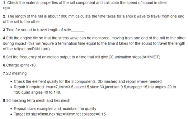
Theory:
Preliminary comments regarding the incremental nature of Explicit and Implicit Analysis:
A geometric and/or material nonlinear analysis requires incremental load (or displacement) steps. At the end of each increment, the structure geometry changes and possibly the material is nonlinear or the material has yielded. Each of these things, geometry change or material change, may then need to be considered as you update your stiffness matrix for the next increment in the analysis.
Explicit:
An Explicit FEM analysis does the incremental procedure and at the end of each increment updates the stiffness matrix based on geometry changes (if applicable) and material changes (if applicable). Then a new stiffness matrix is constructed and the next increment of load (or displacement) is applied to the system. In this type of analysis, the hope is that if the increments are small enough the results will be accurate. One problem with this method is that you do need many small increments for good accuracy and it is time-consuming. If the number of increments are not sufficient the solution tends to drift from the correct solution. Furthermore, this type of analysis cannot solve some problems. Unless it is quite sophisticated it will not successfully do cyclic loading and will not handle problems of snap-through or snapback. Perhaps most importantly, this method does not enforce the equilibrium of the internal structure forces with the externally applied loads.
Implicit:
An Implicit FEM analysis is the same as Explicit with the addition that after each increment the analysis does Newton-Raphson iterations to enforce equilibrium of the internal structure forces with the externally applied loads. The equilibrium is usually enforced to some user-specified tolerance. So this is the primary difference between the two types of anlysis, Implicit uses Newton-Raphson iterations to enforce equilibrium. This type of analysis tends to be more accurate and can take somewhat bigger increment steps. Also, this type of analysis can handle problems better such as cyclic loading, snap-through, and snap back so long as sophisticated control methods such as arc length control or generalized displacement control are used. One drawback of the method is that during the Newton-Raphson iterations one must update and reconstruct the stiffness matrix for each iteration. This can be computationally costly. (As a result, there are other techniques that try to avoid this cost by using Modified Newton-Raphson methods.) If done correctly the Newton-Raphson iterations will have a quadratic rate of convergence which is very desirable.
As to the question of which method to use, the answer is that it depends. The type of analysis that is sufficient for your needs will depend on the type of problem that you are trying to solve. Often times since dynamic analyses are computationally intensive they are done with the explicit method. However, for static problems now days it is becoming more common to do the full Implicit type of analysis.
( Source of above definitions: https://imechanica.org/node/5396 )
What is the time step in FEA?
In the context of explicit analysis, time step is the time required for a shock wave to propagate across the smallest distance of the element. A run is a single model simulation and it starts at time zero and continues till the user-defined endpoint is reached. The basic time unit in the run is the time step.
The time step is directly dependent on the length of the element and inversely proportional to the speed of sound of material. The speed of sound of the material is dependent on both material modulus and density of the material. So, if the material is stiffer (higher modulus of elasticity), the speed of sound increases resulting in a lower solution time step.
A brief explanation of various tools, processes and methods that are used in solving the problems given above are appropriately mentioned below with the steps of carrying out that particular process.
Solutions to the asked problems:
1. Performing various operations as asked on Radioss Files
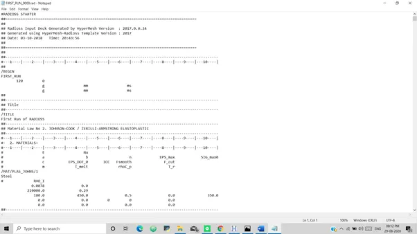
1. Check the material properties of the rail component and calculate the speed of sound in steel rail=_______
Solution: As per the above picture, we can easily see that the density is, Rho= 0.0078 and the value of E is 210000 MPa, so as asked the speed of sound in a material is given as:
On substitution of values of E and rho in the above equation, we get,
C = 5188.74 m/s (or mm/ms)
2. The length of the rail is about 1000 mm.calculate the time takes for a shock wave to travel from one end of the rail to the other.
Solution: Given values are l=1000 mm and c= 5188.74 m/s
Time taken,
So, we get Time taken = 0.1927 ms
3.Time for sound to travel length of rail=______
Solution: As solved in the previous question, the length of the rail is 1000 mm, so the Time for sound to travel the length of rail is 0.1927 ms
4.Edit the engine file so that the stress wave can be monitored, moving from one end of the rail to the other during impact -this will require a termination time equal to the time it takes for the sound to travel the length of the rail(set on/RUN card)
Solution: Here the termination time=time taken to travel the length of the rail. (Solution image attached at the end of Question 6)
5.Set the frequency of animation output to a time that will give 20 animation steps(/ANIM/DT)
Solution: To get 20 animation steps means to divide the given time the sound takes to travel the length of rail in such a way that we get 20 time-steps, so on dividing the value obtained earlier i.e. 0.1927/20 gives a step of 0.009635 (Solution image attached at the end of Question 6).
6.Change /print -10.
Solution image for questions 4,5 and 6. (Edited engine file opened on notepad)
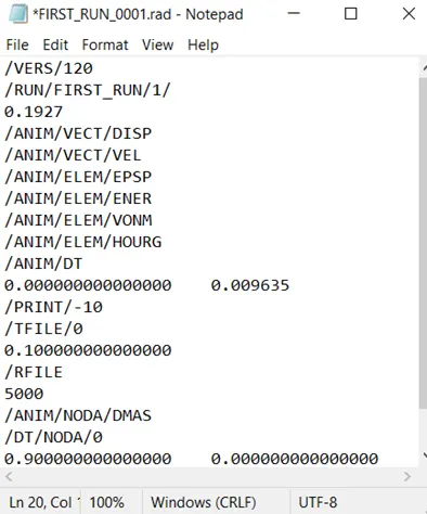
The edited values are visible in this file and appropriate changes would taken into effect during further operations that take place.
2. 3D Meshing of Housing:
The housing given in the problem consists of the components cover and hub.
Firstly taking up the analysis of the cover:
Given Component:
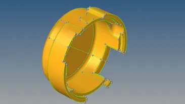
Firstly 2D meshing of this component was done using only Triangular elements, under the given quality criteria mentioned in the problem 7.
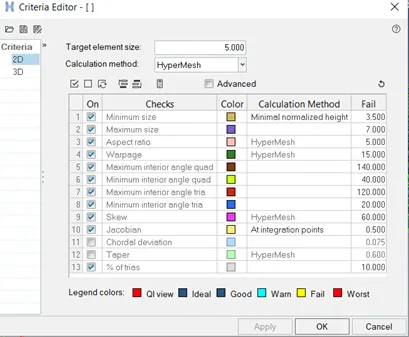
After 2D Meshing using the Automesh feature and then correcting the elements violating the criteria using Element Optimize, Place Node, Element Cleanup and Remeshing Features.
We get the following 2-D Meshed Surface:
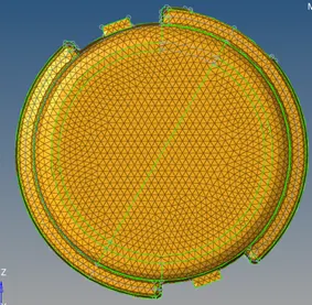
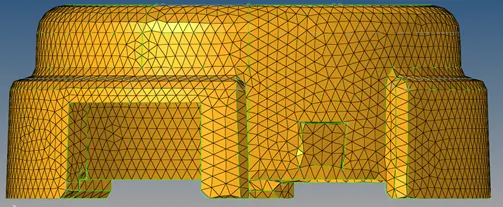
Now, after checking the above given quality criteria:
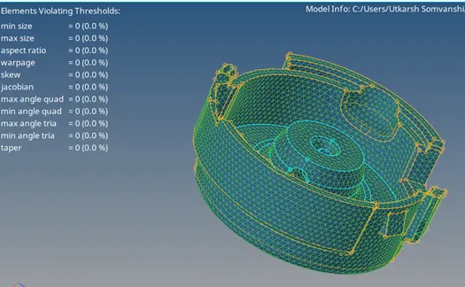
Now after doing 2D meshing, 3D meshing was done using the following steps:
- Go to 3D -> Tetramesh
- Set appropriate parameters, like here it was Tet size = 5mm and tet collapse = 0.15
- After doing tetrameshing, it is to be checked for quality from Tools -> Check Elements
- There would be some elements failing, so that is corrected by setting up appropriate tetramesh parameters and then remeshing. ( We can see 0% failed in the image below, which was around 8% before corrections
- After that again Check elements is done and meshing would be proper this time.

Now, taking up the analysis of the hub:
Given Component:
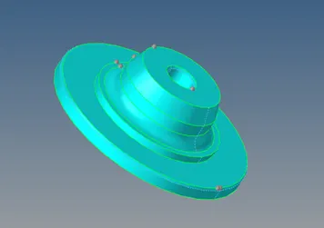
Meshed Model of hub:
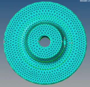
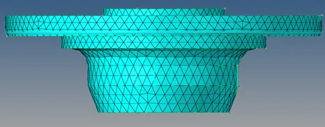
Similar steps as above were performed and similar results were obtained. But this time tetrameshing was done using the utility browser which could be accessed through View -> Browsers -> Hypermesh -> Utility -> Quick Tetramesh
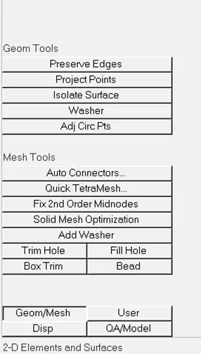
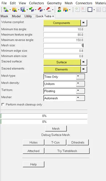
In the above image, on opening set the appropriate Mesh size and Mesh type which were 5 and trias only respectively in this case. After that select the geometry of the model and click on Mesh and finally we will obtain a fully tetrameshed model, which may have some defects violating thequality criteria which can be corrected by following the remeshing process explained above in the case of the cover.
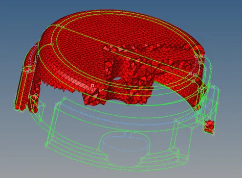
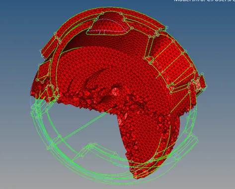
Final 3D tetrameshed model having both hub and cover:
A part of the model was masked for a proper view of the elements
3. 3D Meshing of Arm Bracket:
Given Component:
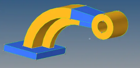
Now, the explaination of how the all the indivisual elements were meshed is given with attached appropriate images.
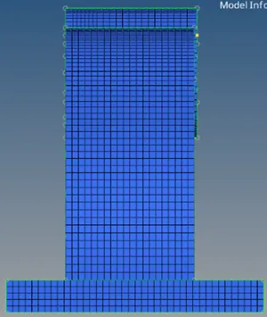
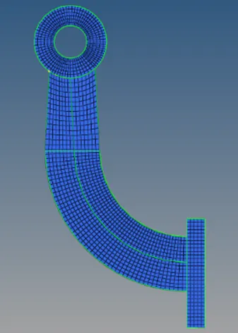
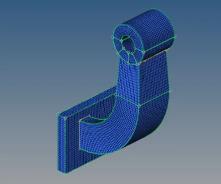
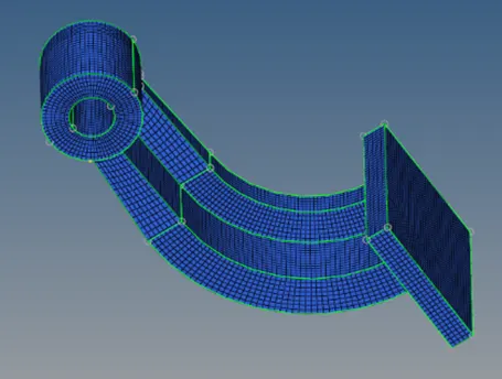
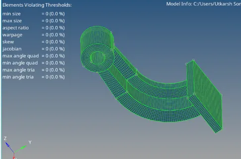
Indivisual Components and explaination of their meshing procedure:
- Base:
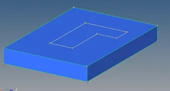
Steps:
- Both the surfaces of the upper face of the base was simply selected and meshed.
- After that 3D -> Element offset
- Set the number of layers that are needed and then select the sufaces along which mesh is required, which are side surfaces in this case.
- Click on offset to obtain the final mesh in this case.
- Arm (Curved portion):
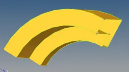
Steps:
- In this case go to Spin option instead of Element offset.
- Mask all elements of the base except the common face
- Select common elements
- Set the angle, which is 90 in this case
- Select the centre of the cuvature and then spin the geometry to obatin the 3D meshed model.
- Arm (Straight portion):
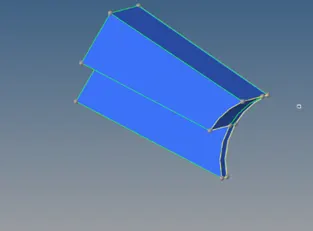
Steps:
- Go to Linear solid option in 3D
- Extract the face element of the Curved arm and locate the face joining Curved and straight portion.
- Mesh the common surface of the current component and the boss with exactly similar mesh as in previous step.
- Select the both the surfaces mentioned in steps ‘b’ and ‘c’.
- Select similar nodes on both the surfaces for alignment.
- Click solids to obtain the mesh.
- Boss:
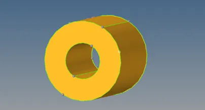
Steps:
- Mesh the top surface of the boss with properly numbered and aligned elements.
- Go to Solid Map option under 3D.
- Place a node on the bottom surface such that it is place I a traight line along the edge nodes of straight arm.
- Select top elements and bottom surface.
- Set along geometry to mixed and select a line along the curved surface.
- Click on mesh and the geometry is obtained.
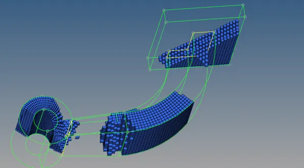
Final Views of 3D meshing of the Arm Bracket:
Masking was done to get a proper view.
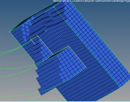
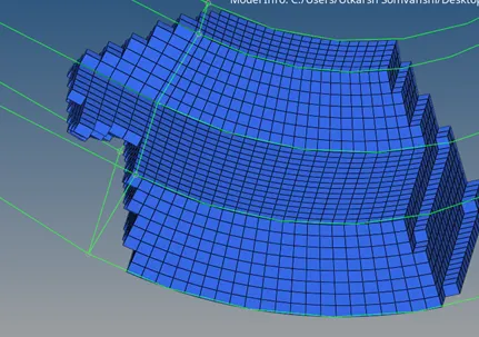
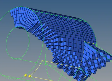
4. 1D Meshing:
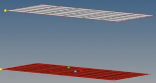
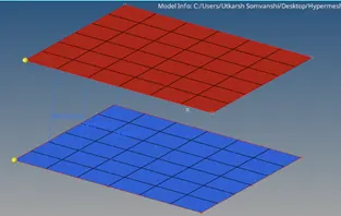
A simple surface was given, it was meshed first of all, and then the distance of surface from the frame having a node was measured ann the mesh was duplicated and translated to obtain proper surfaces.
After that one by one different nodes were selected and a spring, a truss and beam was placed.
Before:
After:
Results:
- Speed of sound in steel = 5188.74 m/s
- Time taken to travel in the length of a rail = 0.1927 ms
- Time step for 20 animation steps = 0.009635 ms
- In the meshing exercise, on following proper steps, a proper mesh was obtained for further analysis under the given threshold values for quality.
Conclusions:
Quality assurance and failure analysis are one of the most important methodologies used in the industry to keep up the standard of the product. Using Hypermesh and Radioss for failure checking with the help of finite element analysis and various other techniques, is one of the best tools to analyse to overcome flaws and hence increase the quality and confidence on that product. In this project report, mostly the focus was on 3D meshing of the components for their further analysis with the help of various 3D meshing tools available. Also a simple exercise of 1D meshing and Radioss was done.
Some of the challenges/problems encountered during this project were:
- Maintaining a proper alignment of triangular elements on edges and complex portions.