To run simulations on a Crash tube model for different crash property values using HyperMesh, HyperCrash and RADIOSS solver.
PROJECT REPORT
SKILL LYNC ASSIGNMENT 5
Aim:
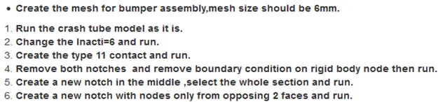
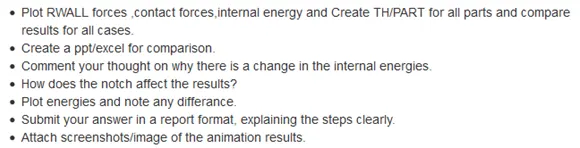
To run simulations on a Crash tube model for different crash property values on RADIOSS solver, and also to mesh a Bumper assembly as per the criteria given.
Objectives:
Theory:
Interface/ Contact Modeling:
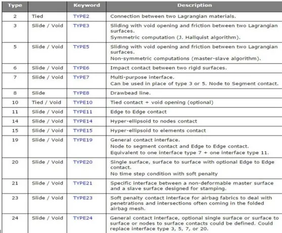
RADIOSS has a large number of contact types suitable for many applications. In RADIOSS an interface is created by defining the master segment and slave node set. The master segment can be parts components, elements, contact surface, node surface sets and slave entities can be parts components and node sets.
- TYPE7, variable stiffness, node to surface contact
- TYPE11, variable stiffness, edge to edge contact 162
- TYPE19, combination of Type 7+11
- TYPE24 , linear stiffness, node to surface, and surface to surface contact
The Penalty Method:
Interfaces using the penalty method are based on master/slave treatment. Contact can only occur between a set of slave nodes and a set of master segments. A gap distance is defined to determine whether or not a node is in contact with a segment. Spring elements that generate resistive forces as a function of penetration are created between the slave node and its projection. The spring stiffness is automatically computed according to the material and property of both master segment and slave node. The time step may be affected by the interface stiffness.
Types of contacts:
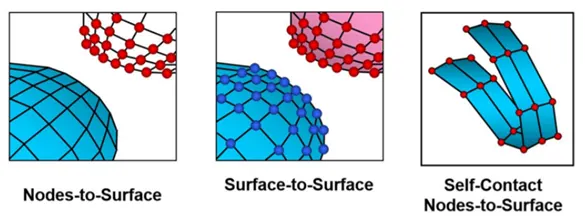
Master & Slave:
The coarser the mesh, the stiffer the structure will be provided the material and structural properties are same. Hence, the Master is typically meshed coarser so that the Slave does not penetrate into master. That is why we choose stiffer structure as master and compliant as slave.
Types of Interfaces
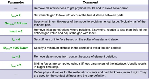
Important Interface Parameters
- Igap: Determines how the size of the gap is calculated
- Gapmin: Minimum gap for activation of interface
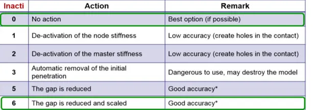
- Inacti: Action to take if initial penetrations exist
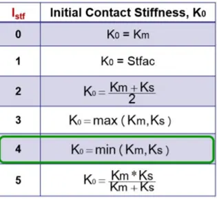
- Istf: Affects how the stiffness of the interface is calculated
- Iform: Friction formulation
- Stmin: Minimum stiffness to use in the interface
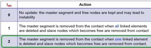
- Idel: Update For Deleted Elements Due To Failure
Interface Type 7: Nodes to Surface Contact:
- Automatic node to surface contact interface using penalty method with variable stiffness
- A gap is defined around the master segment and the slave nodes
- The contact gap can be constant or variable
- Resistive forces are applied to keep slave nodes out of the contact gap
- Interface time step is computed to insure stability
Recommended Values:
- Istf=4
- Igap=2
- Fscale_Gap=0.8
- INACTI=6
- Gap_min=0.1
- Fric = 0.1
- Iform=2





Interface Type 11: Edge to Edge Contact
- This interface simulates impact between edge to Edge or lines. A line can be a beam or truss element or a shell edge or spring elements. In association with interface TYPE7, interface TYPE11 solves the locking cases
- Defined by identifying master and slave lines (edges)
- Impacts occur between a master and a slave line. A slave line can impact on one or more master lines. A line can belong to the master and the slave side. This allows self-impact.
- Works similar to Type 7 in terms of Penalty formulation, Gap definition and Search method
Interface Type 19: Combination of Type 7+11
- Combination of two symmetric TYPE7 interfaces and one TYPE11 interface
Interface Type 24: General Linear Contact
- Penalty stiffness is constant and therefore, the time step is not affected (for standard penalty stiffness).
- Solid elements are given a zero gap.
- Three types of inputs contacts can be defined: single surface, surface to surface, or nodes to surface.
- Recommended for all models where there is no physical gap (solids to solids) or there is initial interference between parts
Bumper Meshing:
Firstly, all the components were meshed indivisually taking mesh size as 6 as asked.
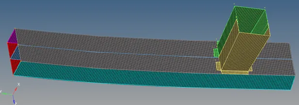
As shown above the two components were not connected together so a connection had to be made.
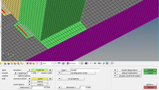
So a spot weld connection was made accordingly by connecting the flanges to the bumper surface as shown below.
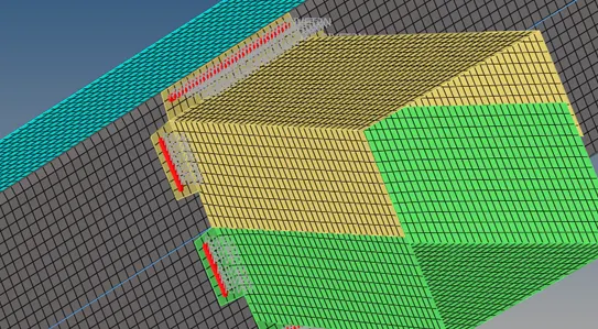
The final meshed and spot-welded model obtatained after performing all the operations is shown below:
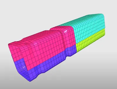
Now, the given model on which the simulations are to be done is as follows:
Unit system used throughout the report: kN mm ms kg
Case 1: Run the crash tube model as it is without making any change in any of the parameters.
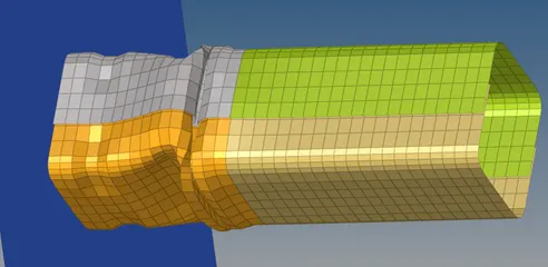
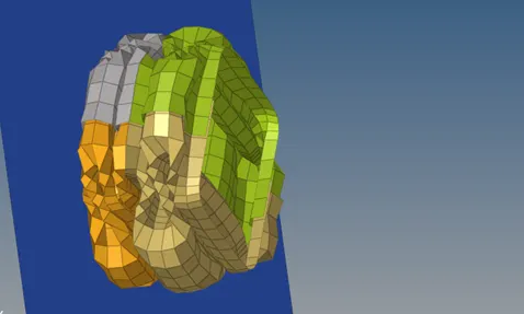
Due to the presence of notches, the initiation of the deformation would be from the notch itself. The boundary conditions are set up accordingly so that the application of force is in one direction perpendicular to the rigid wall in -Z direction as per the coordinates. As shown in the figure below it is clearly visible that the deformation is starting from the notches. The Von Mises stress concentration at the notch is maximum at the notch during the simulation starting.
Von Mises stress contour:
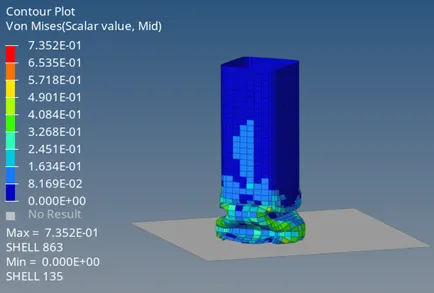
Maximum Von Mises Stress: 7.352E-01
As we can clearly see with the help of colours that the maximum stresses are at or near the notch region.
Now, the analysis of various Forces and energies is as follows:
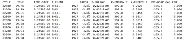
ELAPSED TIME = 117.80 s
TOTAL NUMBER OF CYCLES: 83469
Energy Error: -3.8%
Internal Energy: 0.4202E+05
Kinetic Energy: 592.8
The plots of Internal Energy, Kinetic Energy, Contact Energy, Hourglass Energy and the Total energy are as follows:
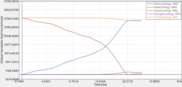
Initially there is some velocity given to the rigid body which eventually decreases upon due to crushing and reaches a final small value of 592.8.
Also, there is no initial Forces so the initial internal energy is 0 and upon the action of stresses and strains and absorption of kinetic energy the internal energy increases. Hourglass energy is 0 throughout because Qeph elements are used in shell formulation.
Contact energy increases towards the end because of the dissipation of heat as a lot of elements are in contact with each other due to crushing.
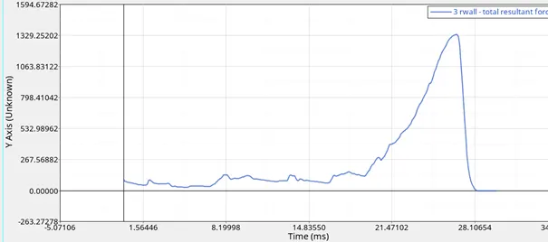
The total resultant force on the rigid wall is as follows:
Case 2: Change the value of Inacti to 6 and then run the simulation:
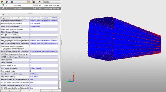
Open hypercrash, import the model, go to LoadCase and then select Type 7 to edit it and change the value of incati to 6.
The change in value of inacti implied the treatment of the initial penetrations.
Due to the presence of notches, the initiation of the deformation would be from the notch itself. The boundary conditions as set up accordingly so that the application of force is in one particular perpendicular to the rigid wall in -Z direction as per the coordinates. As shown in the figure below it is clearly visible that the deformation is starting from the notches. The Von Mises stress concentration at the notch is maximum at the notch during the simulation starting. Similar to the first case.
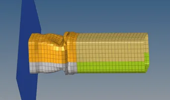
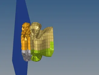
Von Mises stress contour:
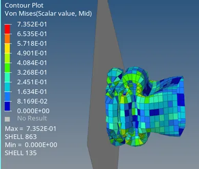
Maximum Von Mises Stress: 7.352E-01
As we can clearly see with the help of colours that the maximum stresses are at or near the notch region.
Now, the analysis of various Forces and energies is as follows:
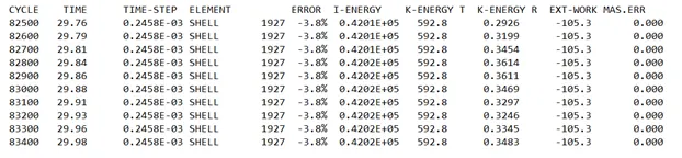
ELAPSED TIME = 210.29 s
TOTAL NUMBER OF CYCLES: 83469
Energy Error: -3.8%
Internal Energy: 0.4202E+05
Kinetic Energy: 592.8
The plots of Internal Energy, Kinetic Energy, Contact Energy, Hourglass Energy and the Total energy is as follows:
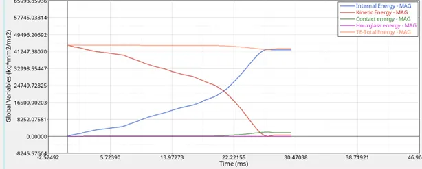
Initially there is some velocity given to the rigid body which eventually decreases upon due to crushing and reaches a final small value of 592.8.
Also, there is no initial Forces so the initial internal energy is 0 and upon the action of stresses and strains and absorption of kinetic energy the internal energy increases. Hourglass energy is 0 throughout because Qeph elements are used in shell formulation.
Contact energy increases towards the end because of dissipation of heat as a lot of elements are in contact with each other due to crushing.
The total resultant force on the rigid wall is as follows:
Case 3: Create a type 11 contact with recommended properties and then run the simulation:
Open hypercrash, import the model, the go to LoadCase > Contact Interface > Create New contact of type 11 type i.e Edge to edge contacts are present.
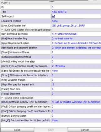
When the new contact gets created enter the recommended values as given above.The explaination of why each recommended value is choses for crash analysis is given above in theory.
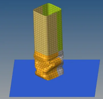
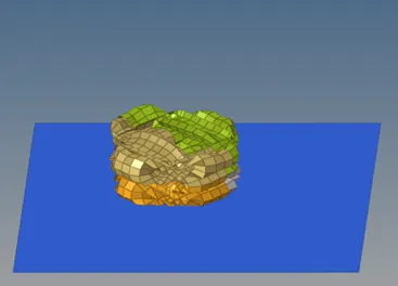
Due to the presence of notches, the initiation of the deformation would be from the notch itself. The boundary conditions as set up accordingly so that the application of force is in one particular perpendicular to the rigid wall in -Z direction as per the coordinates. As shown in the figure below it is clearly visible that the deformation is starting from the notches. The Von Mises stress concentration at the notch is maximum at the notch during the simulation starting.
Von Mises stress contour:
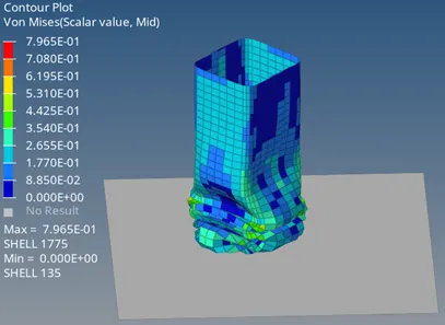
Max Von Mises stress : 7.965E-01
Now, the analysis of various Forces and energies is as follows:
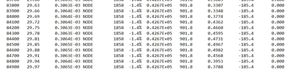
ELAPSED TIME = 258.32 s
TOTAL NUMBER OF CYCLES: 85006
Energy Error: -1.4%
Internal Energy: 0.4267E+05
Kinetic Energy: 901.8
The plots of Internal Energy, Kinetic Energy, Contact Energy, Hourglass Energy and the Total energy is as follows:
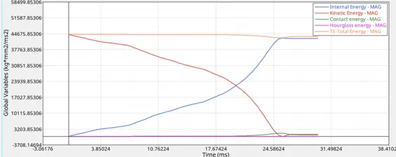
Initially there is some velocity given to the rigid body which eventually decreases upon due to crushing and reaches a final small value of 901.8
Also, there is no initial Forces so the initial internal energy is 0 and upon the action of stresses and strains and absorption of kinetic energy the internal energy increases. Hourglass energy is 0 thoughout because Qeph elements are used in shell formulation.
Contact energy increases towards the end because of dissipation of heat as a lot of elements are in contact with each other due to crushing.
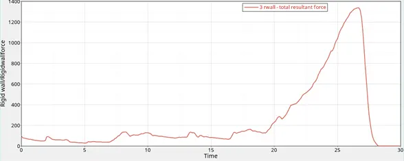
The total resultant force on the rigid wall is as follows:
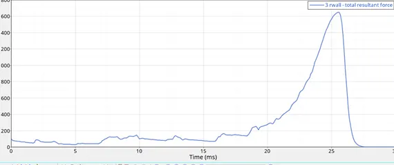
Case 4: Remove all the notches as well as the boundary conditions and run the simulation.
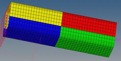
Open hypercrash, import the model, and then delete the boundary condtions.Then open hypermesh and use it align the notches at a proper position. Model after notch removal is as follows:
Now as the notches are removed so the deformation takes accordingly, and also since there are no boundary conditions so the motion of the crush tube is not restricted in just one direction.
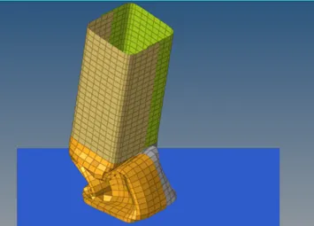
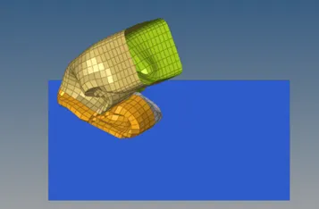
Here we can see that because of the removal of boundary conditions, there is a lateral displacement during simulation as well.
Von Mises stress contour:
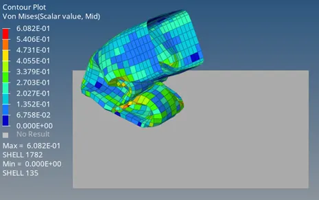
Maximum Von Mises Stress: 6.082E-01
Now, the analysis of various Forces and energies is as follows:

ELAPSED TIME = 123.80 s
TOTAL NUMBER OF CYCLES: 61099
Energy Error: -0.6%
Internal Energy: 0.1351E+05
Kinetic Energy: 0.2979E+05
The Kinetic energy here is observed to be more than the case 1 and 2 because there are no restrictions present here.
The plots of Internal Energy, Kinetic Energy, Contact Energy, Hourglass Energy and the Total energy is as follows:
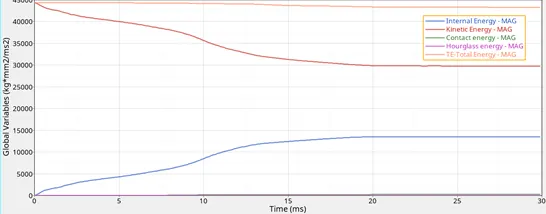
Initially there is some velocity given to the rigid body which eventually decreases upon due to crushing and reaches a final value of 0.2979E+05
Also, there is no initial Forces so the initial internal energy is 0 and upon the action of stresses and strains and absorption of kinetic energy the internal energy increases. Hourglass energy is 0 throughout because Qeph elements are used in shell formulation.
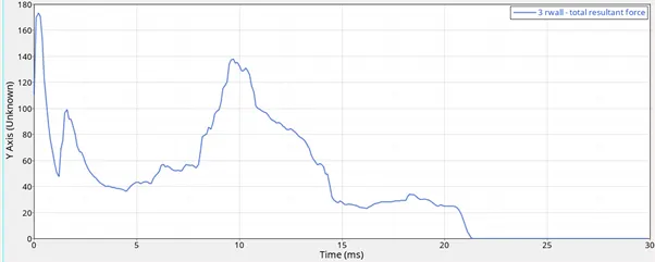
The total resultant force on the rigid wall is as follows:
Case 5: Create a notch at the centre, set up boundary conditions and then run the simulation:
Now in this case, we again define the boundary conditions and do the analysis by creating a notch in the exact centre of the given model
Due to the presence of notches, the initiation of the deformation would be from the notch itself. The boundary conditions as set up accordingly so that the application of force is in one particular perpendicular to the rigid wall in -Z direction as per the coordinates. As shown in the figure below it is clearly visible that the deformation is starting from the notches. The Von Mises stress concentration at the notch is maximum at the notch during the simulation starting. We can clearly see in the simulation figures below that the deformation is starting from the middle notch. But the values of different energies and forces would be different from Case 1 and 2.
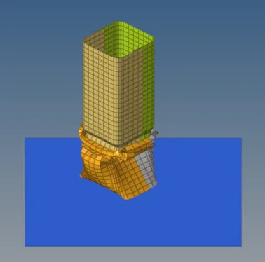
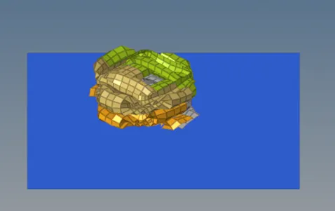
Von Mises stress contour:
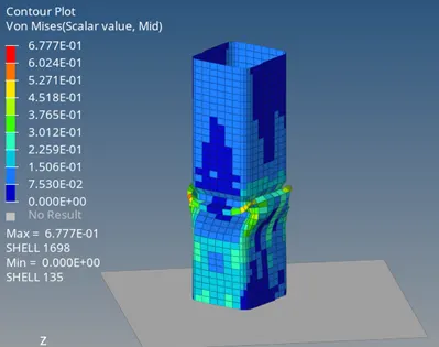
Maximum Von Mises stress : 6.777E-01
Now, the analysis of various Forces and energies is as follows:
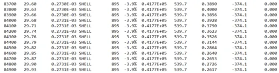
ELAPSED TIME = 128.03 s
TOTAL NUMBER OF CYCLES: 85163
Energy Error: -3.9%
Internal Energy: 0.4177E+05
Kinetic Energy: 529.7
The plots of Internal Energy, Kinetic Energy, Contact Energy, Hourglass Energy and the Total energy is as follows:
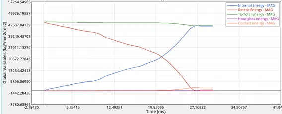
Initially there is some velocity given to the rigid body which eventually decreases upon due to crushing and reaches a final small value of 529.7
Also, there is no initial Forces so the initial internal energy is 0 and upon the action of stresses and strains and absorption of kinetic energy the internal energy increases. Hourglass energy is 0 throughout because Qeph elements are used in shell formulation. The contact energy increases slightly at the end because of the heat dissipation as many elements come in contact after the total crushing.
The total resultant force diagram on the rigid wall is as follows:
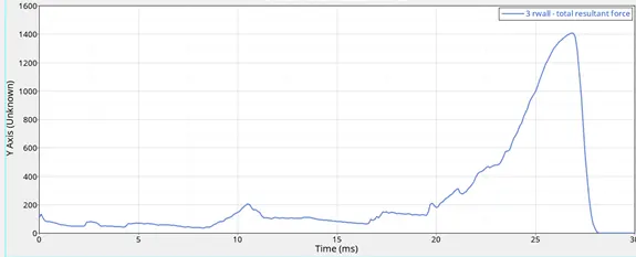
Case 6: Create a new notch only on 2 opposing faces.
Now in this case, we again define the boundary conditions and do the analysis by creating a notch in the exact centre on two opposite faces of the given model
Due to the presence of notches, the initiation of the deformation would be from the notch itself. The boundary conditions as set up accordingly so that the application of force is in one particular perpendicular to the rigid wall in -Z direction as per the coordinates. As shown in the figure below it is clearly visible that the deformation is starting from the notches. The Von Mises stress concentration at the notch is maximum at the notch during the simulation starting. We can clearly see in the simulation figures below that the deformation is starting from the middle notch. But the values of different energies and forces would be different from Case 1 and 2 as well as from case 5 because of different notches.
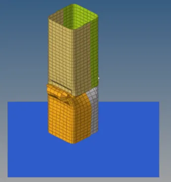
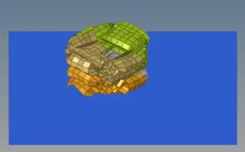
Von Mises stress contour:
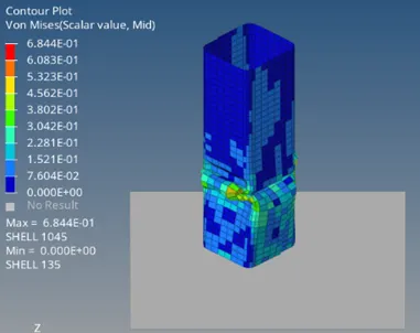
Maximum Von mises stress : 6.844E-01
Now, the analysis of various Forces and energies is as follows:
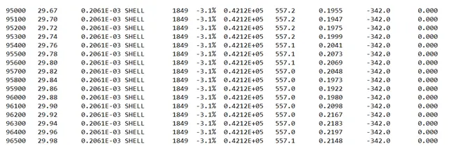
ELAPSED TIME = 236.97s
TOTAL NUMBER OF CYCLES: 96579
Energy Error: -3.1%
Internal Energy: 0.4212E+05
Kinetic Energy: 557.1
The plots of Internal Energy, Kinetic Energy, Contact Energy, Hourglass Energy and the Total energy is as follows:
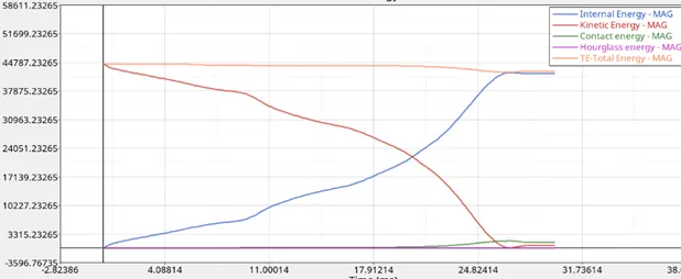
Initially there is some velocity given to the rigid body which eventually decreases upon due to crushing and reaches a final small value of 557.1
Also, there is no initial Forces so the initial internal energy is 0 and upon the action of stresses and strains and absorption of kinetic energy the internal energy increases. Hourglass energy is 0 throughout because Qeph elements are used in shell formulation.
Contact energy increases towards the end because of dissipation of heat as a lot of elements are in contact with each other due to crushing.
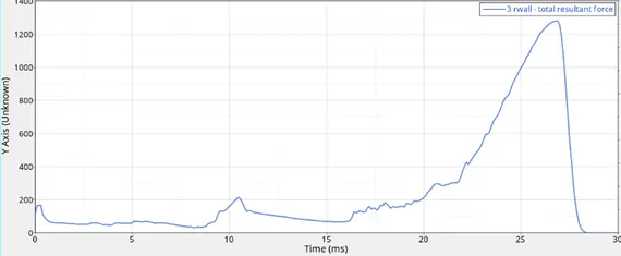
The total resultant force on the rigid wall is as follows:
RESULT:
Different values obtained after conduction of simulations of different cases under different given conditions are as follows, several variations which are visible are accounted in the explanations above.
Max rigid wall force can be compared from the graphs above.
|
CASE |
Time Taken |
Energy Error |
Mass Error |
Internal Energy |
Kinetic Energy |
Von-Mises Stress |
|
1 |
117.80 s |
-3.8% |
0 |
0.4202E+05 |
592.8 |
7.352E-01 |
|
2 |
210.29 s |
-3.8% |
0 |
0.4202E+05 |
592.8 |
7.352E-01 |
|
3 |
258.32 s |
-1.4% |
0 |
0.4267E+05 |
901.8 |
7.965E-01 |
|
4 |
123.80 s |
-0.6% |
0 |
0.1351E+05 |
0.2979E+05 |
6.082E-01 |
|
5 |
128.03 s |
-3.9% |
0 |
0.4177E+05 |
539.7 |
6.777E-01 |
|
6 |
236.97 s |
-3.1% |
0 |
0.4212E+05 |
557.1 |
6.844E-01 |
CONCLUSION:
After running simulations for all 7 cases with appropriate values, different results were obtained. Contours and Energy graphs were plotted and the values were accordingly extracted and compared.