To carry out Geometry Cleanup and Meshing operations under the given Quality criterias using Hyperworks
PROJECT REPORT
Skill Lync Assignment 1
AIM:
To carry out geometry clean-up and meshing operations using HyperMesh on the given 3 files.
OBJECTIVES OF THE PROJECT:
The main objectives of this project are as follows:
- To carry out geometry clean-up operations such as toggling and combining edges, trimming of unwanted parts, filling up of small holes (holes with a diameter less than 5mm), deleting or adding lines and points, measuring distances for checking different criteria etc on the given geometry.
- After geometry clean-up operation, middle surface extraction is to be done followed by the clean-up of the middle surface too.
- After that meshing has to be done with a mesh size of 5 mm and taking maximum and minimum limits of the mesh size to be 3.5 and 7 mm respectively.
- Finally, the thickness is to be given to the geometry by the creation of a generic property.
The above operations were performed on 3 different models given.
THEORETICAL ASPECTS:
HyperMesh User Interface
- Graphics area – displays the model
- Toolbar – Gives access to commonly used tools via icons
- Pull Down Menu – places functionality into groups, accessible via pull-downs
- Menu Pages – divides the main menu into groups based on function
- Main Menu – contains “panels” grouped in columns
- Panels – menu items/functions for interacting with HyperMesh
- Sub-panels – divides panel into similar tasks related to the panel’s main function
- Command Window – lets the user type in and execute TCL commands
- Available through the View drop-down menu (turned off by default)
- Tab Area – contains the following tabs:
- Solver, Model, Utility, Include, Import, Export, Connector, Entity State, etc.
- Status Bar – shows the status of operations being performed
- Indicates the “current” Include file, Component Collector, and Load Collector
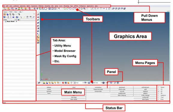
The following is a list of the geometric entities which can be created and edited within HyperMesh:
- Nodes
- Free Points
- Fixed Points
- Lines
- Faces
- Surfaces
- Solids
WHAT IS FINITE ELEMENT METHOD?
The finite element method (FEM) is a numerical technique used to perform finite element analysis (FEA) of any given physical phenomenon.
It is necessary to use mathematics to comprehensively understand and quantify any physical phenomena, such as structural or fluid behaviour, thermal transport, wave propagation, and the growth of biological cells. Most of these processes are described using partial differential equations (PDEs). However, for a computer to solve these PDEs, numerical techniques have been developed over the last few decades and one of the most prominent today is the finite element method.
MODEL 1:
- Given Model:
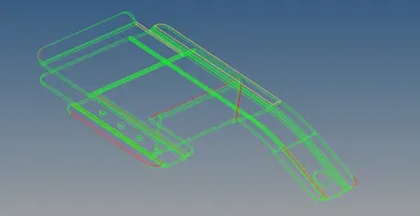
Here we can see various red lines (free edges) as well as unwanted lines, which are to be removed to clean up the geometry. There are four types of surface edges:
- Free edges
- Shared edges
- Suppressed edges
- Non-manifold edges
After their removal by toggle line operation and after trimming of extra material on the geometry, the model looked like:
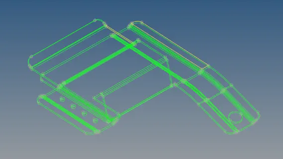
The toggle edge operation is visible with a tolerance of 0.001
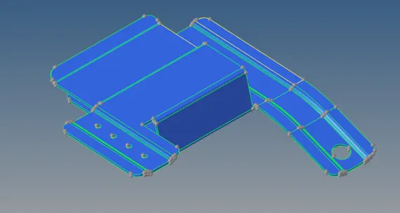
This the solid geometry of the cleaned-up model.
Now, middle surface extraction is done:
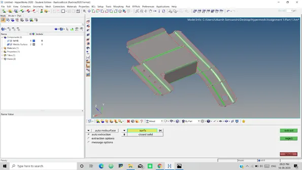
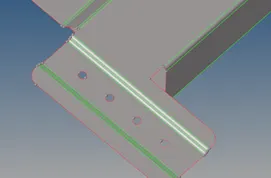
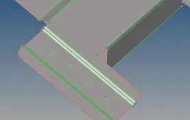
This is the model after the extraction of its middle surface. Now, the radius of the holes was determined with the use of distance calculation feature, and as the radius was found lesser than the given limits so they were filled up with the help of fillet surface and edge was toggled.
Before:
After:
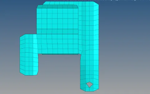
Now after obtaining a cleaned up middle surface of the meshing was done using Automesh feature on different surfaces taking the mesh size as 5, and then mesh was made symmetrical using Rebuild mesh and Smooth features. And the quality was checked whether all elements’ size is within the prescribed limits, i.e. between 3.5 mm to 7 mm.
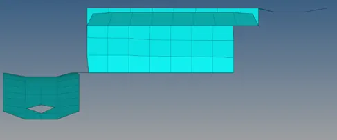
The meshed surface looked like:
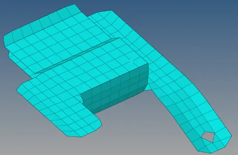
Different views of the meshed surface are:
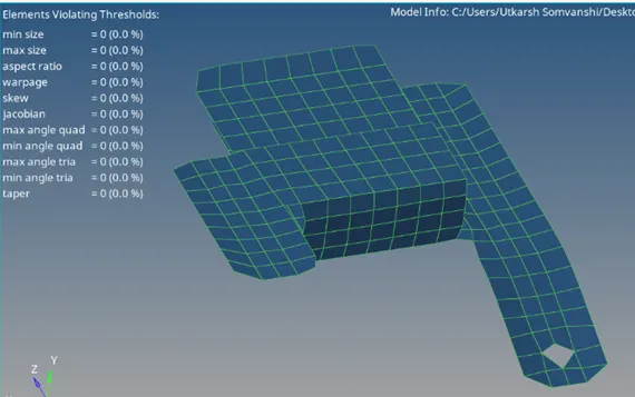
Quality checking was done and all the elements were found to be proper.
Now, finally, after everything, a property 2 was defined in which the measured thickness (0.91 mm) of the original geometry entered, and this property was assigned to the cleaned up and meshed surface, and the following result was obtained:
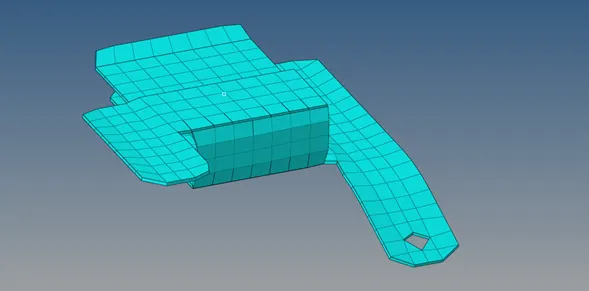
Hence a proper meshed model was obtained which could be further be used for other operations.
MODEL 2:
Given Model:
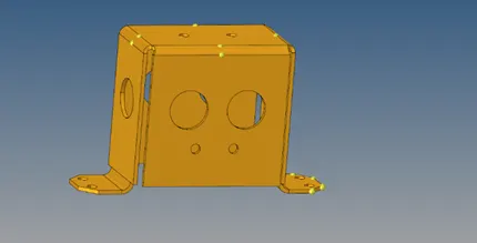
This model had no Free edges or extra surfaces so the mid surface was extracted taking extraction option as a surface offset.
Now, after middle surface extraction is done geometry obtained is:
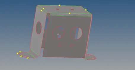
Now, the radius of the holes was determined with the use of distance calculation feature, and as the radius was found lesser than the given limits so they were filled up with the help of fillet surface and edge was toggled as done in the first model.
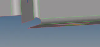
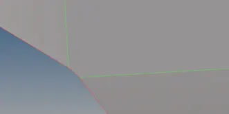
After that the edges which were found to be detached were connected as follows:
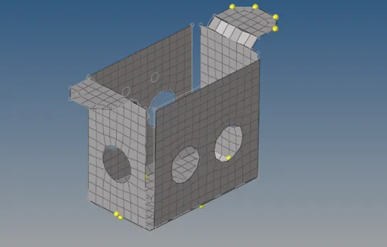
Now after obtaining a cleaned up middle surface of the meshing was done using Automesh feature on different surfaces taking the mesh size as 5, and then mesh was made symmetrical using Rebuild mesh and Smooth features. And the quality was checked whether all elements’ size is within the prescribed limits, i.e. between 3.5 mm to 7 mm, the elements which were failing were corrected using Optimize element, place node etc features.
The meshed surface looked like:
Different views of the meshed surface are:
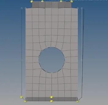
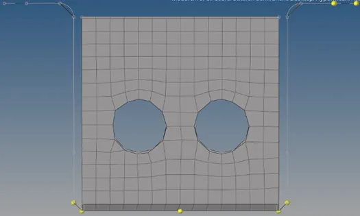
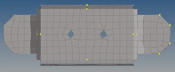
After that Quality checking was done and all the elements were found to be proper.
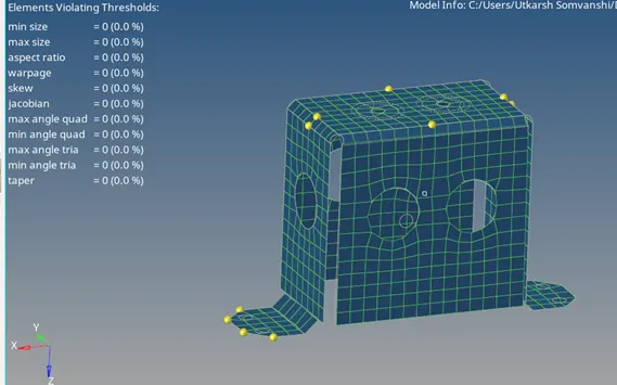
Now, finally, after everything, a property 2 was defined in which the measured thickness (2 mm) of the original geometry entered, and this property was assigned to the cleaned up and meshed surface, and the following result was obtained:
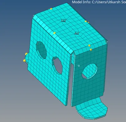
Hence a proper meshed model was obtained which could be further be used for other operations.
MODEL 3:
Given Model:
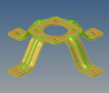
In this model, the same steps as the previous models were repeated and similar results were obtained:
Middle surface extraction is done:
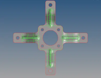
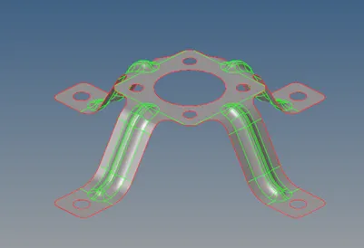
This is the model after the extraction of its middle surface.
Now, the radius of the holes was determined with the use of distance calculation feature, and as the radius was found lesser than the given limits so they were filled up with the help of fillet surface and edge was toggled.
Now after obtaining a cleaned up middle surface of the meshing was done using Automesh feature on different surfaces taking the mesh size as 5, and then mesh was made symmetrical using Rebuild mesh and Smooth features. And the quality was checked whether all elements’ size is within the prescribed limits, i.e. between 3.5 mm to 7 mm.
The meshed surface looked like:
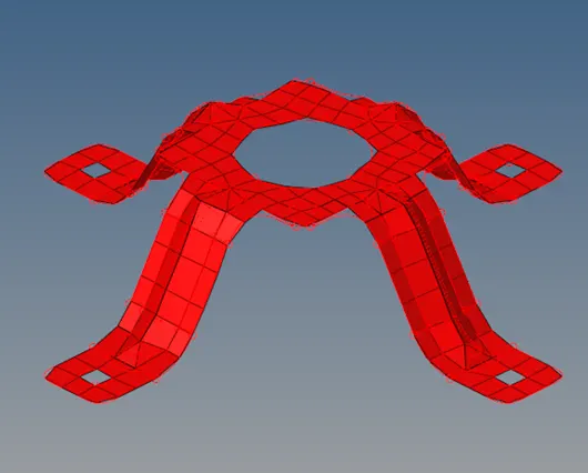
Different views of the meshed surface are:
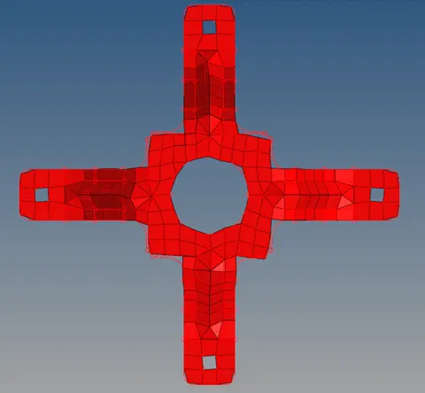
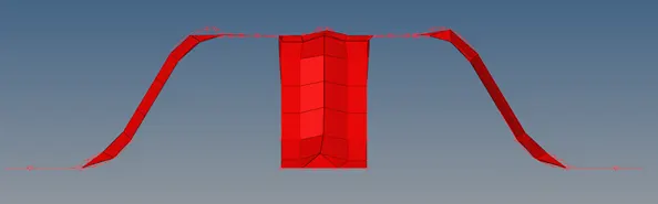
Quality checking was done and all the elements were found to be proper.
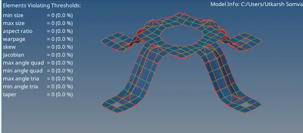
Now, finally, after everything, a property 2 was defined in which the measured thickness (1.8 mm) of the original geometry entered, and this property was assigned to the cleaned up and meshed surface, and the following result was obtained:
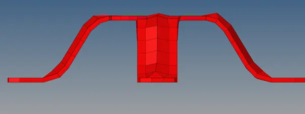
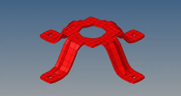
Hence a proper meshed model was obtained which could be further be used for other operations.
CONCLUSIONS:
Quality assurance and failure analysis are one of the most important methodologies used in the industry to keep up the standard of the product. Using Hypermesh for failure checking with the help of finite element analysis is one of the best techniques to overcome flaws. In this assignment, the preliminary step of the FEA was performed which included cleaning up of geometry, deleting extra and unwanted features, extracting mid surface, meshing in an aligned and smooth manner, setting up a few quality parameters and giving a generic property.
Some of the challenges/problems encountered during this project were:
- Meshing in the areas where a hole and edge were in close vicinity with each other.
- Maintaining the size of the mesh on the fillets.