Assignment 3-2D Element Formulation Challenge
Objective:
-
Comparison of results with base simulation and improved shell element properties
1.Using the crash beam file from the previous assignment, change the run time to 55 ms.
2. Change the number of animation steps during simulation to a minimum of 25 and maximum of 60.
3. Run the base simulation without any modification to element properties.
4. At the end of the simulation, do the energy error and mass error checks and determine whether results would be acceptable.
5. If acceptable, Plot rigid wall forces, internal energy, hourglass energy, contact energy, total energy of the simulations.
6. Change all the shell elements properties to recommended properties, save this as separate, rad files and run the simulation.
7. Follow steps 5 and 6.
8. Create a brief report comparing all the results from steps 5 and 6 for both simulations.
9. Comment whether there is any change in the results and why there is any change in the result.
-
PROCEDURE:
- Procedure for objective 1 :
- Changing the runtime to 55 ms. of crash beam file.
Step 1 : Open Hyperworks in Radioss solver.
Step 2 : Import Solver desk runname_0000.rad file (starter input desk).
Step 3 : Follow following commands
Going to model tab
Click on Cards collector
Click on ENG_RUN card
Change Tstop to 55 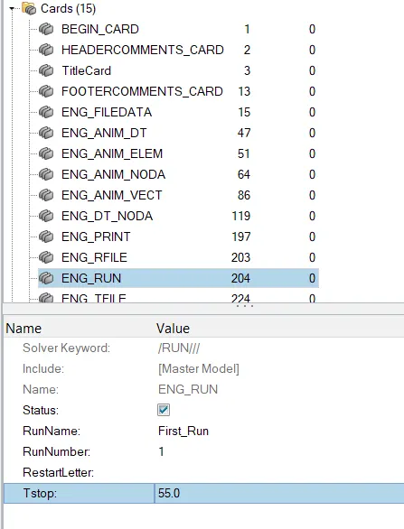
- Procedure for objective 2 :
- Changing the number of animation steps during simulation to a minimum of 25
Run Time(T stop)
The run time is total time taken for sound wave to travel through the entire length of model
This can be calculated by formula
Moving to Tfreq (animation frequency)
For here animation steps must be in between 25 to 60.
So we can choose any value in between 25 to 60. for here we are choosing 30
Animation frequency can be calculated by a formula i.e., Run time /number of animation step
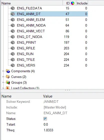
Animation frequency = 55/ 30 = 1.8333
To input this value, go to model browser >> select card >> ENG_ANIM-DT >> and input T freq value as 1.8333 as shown below.
- Procedure for objective 3 :
- Running the base simulation without any modification to element properties.
Step 1 : Set eng_run and eng_anim_dt cards as we did in objective 1 and 2.
Step 2 :
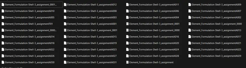
Analysis>Radioss>save as input runname_0000.rad file
Checkbox include collectors
Write (-nt 4) in options (increasing speed of simulation -number of threads 4cpu ).
Click Radioss
Step 3 : Switch to Hyper view
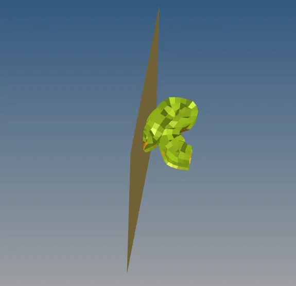
Step 4 : select local model and result runname..h3d file - Simulation starts
- Procedure for objective 4 : Checking and determining the energy error and mass error at the end of the simulation, whether results will be acceptable or not.
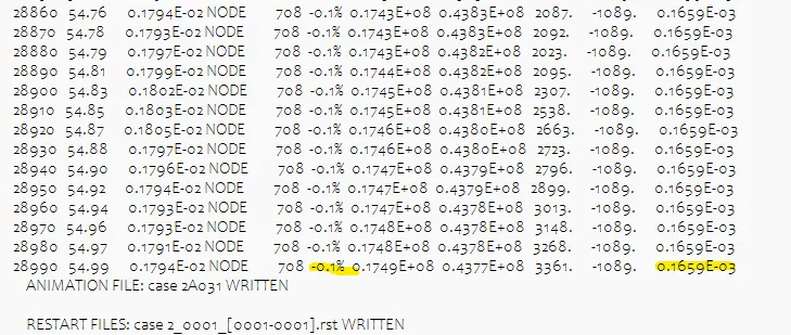
Opening runname_0001.out file, we can see energy error percentage and mass error at the end of computation. 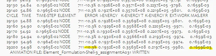
As we know, Energy error must be negative and decreasing, the error must be less than 15% at the end of computation, we find -10.3% energy error and mass error is 0.1659E-0.3
So results are acceptable.- Procedure for objective 5 : Plot Rigid wall forces, Internal energy, Hourglass energy, Contact energy and Total energy of the simulations.
Step 1 : Toolbar>select bropbox list>click Hypergraph 2D
Step 2 : Select data file tab > give file path of runname_T01.file
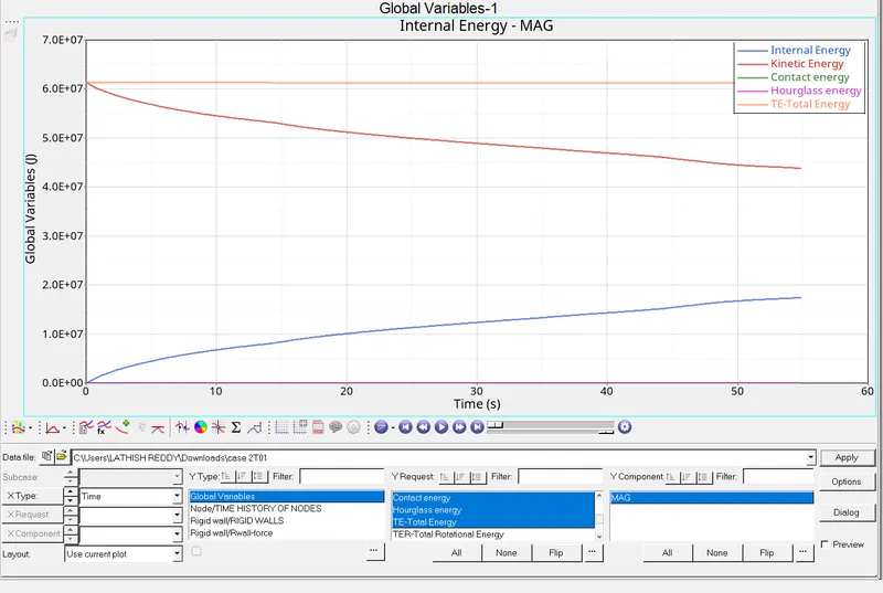
Step 3 : Global variables>select kinetic energy,hourglass energy,internal energy and total energy>select MAG>apply 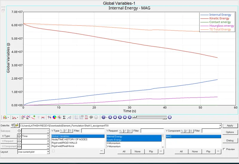
Graph of Internal energy, Hourglass energy, Kinetic energy and Total energy.- Step 4 : Select new plot.
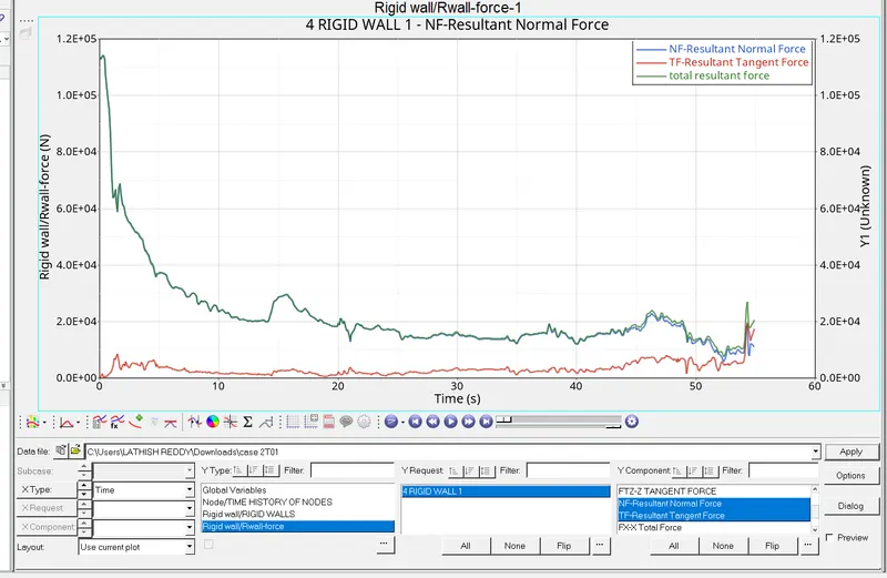
Step 5 : Select rigid wall/R wall forces>4 rigid wall>select resultant normal force, resultant tangent force, total resultant force>apply
Graph of Rigid wall forces 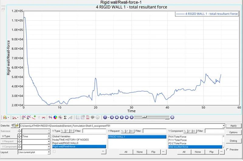
- Procedure for objective 6 : Changing all the shell elements properties to given recommended properties, saving that as separate, rad files and running the simulation.
Step 1 : Making a new folder to save all new property changed files.
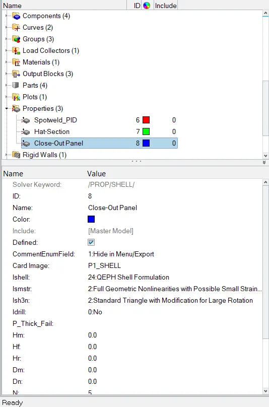
Step 2 : Go to model tree>select properties
Step 3 : Select Hat section and Close out panel property one by one and change
Ishell to 24
Ismstr to 2
Ish3n to 2
N to 5
Ithick to 1
Iplas to 1 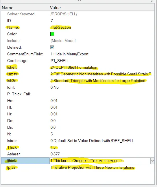
- Procedure for objective 7 :
- Following steps 4 and 5 after changing recommended properties.
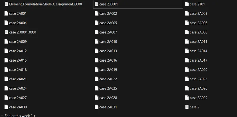
Repeat Procedure of objective 1 to 6 again for this case. - Result of CASE 2 :
Energy error percentage and mass error at the end of computation.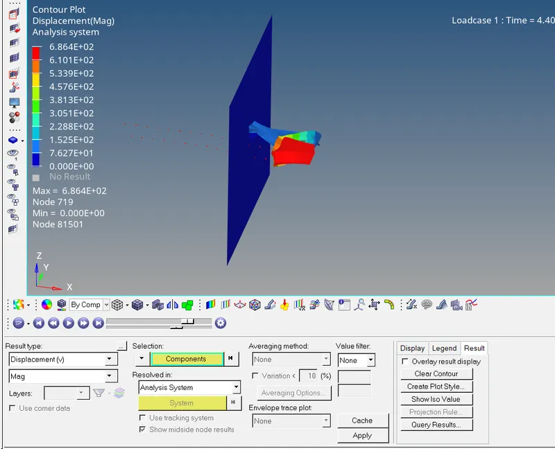
Procedure for objective 8 and 9 :
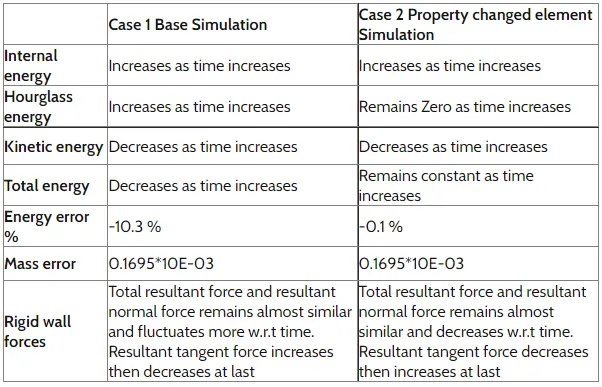
Comparing all the results and Briefing changes of both the cases simulations.
Conclusion :
Energy error decreases and hourglass remains constant after improving shell elements’s property
Details on hourglass energy and modes
Hourglass Energy and Modes.
Hourglass energy :
- It is work done by the forces calculated to resist hourglass modes, takes away from physical energy of the system.
Hourglass modes are zero energy modes of deformation that produce zero strain and no stress. Hourglass mode occurs only in under integrated solid, shell andthick elements. - While post processing results we can see a false deformation with zig zag lines such phenomena is called Hourglass Effect.
Generally this does not happen in experiment but in FEA it happens, this is just a non energy mode which leads to excessive element distortion. More structured and less distorted elements are better for the results
Steps to avoid hourglass deformation
Perturbation (Viscous) Method (Q4 Elements): Ishell 1,2,3,4 -
- When hourglass deformation is happening there is some damping can applied and because of that damping the deformation will be stabilized and that way it will try to control the speed at which it is deforming is happening. When we apply daming it is going to oppose only velocity but not the force. To apply that velocity a force is getting generated by it is going to affect only the speed at which this deformation is happening and that is why while this force is being introduced it is going to add some stiffness (stiffness is added to the element’s node) and this stiffness in the end is going to cause hourglass to be controlled
- Because this force is externally applied but not in natural FEA means this force constituting another energy type is called hourglass energy that is why it is called an artificial energy because it does not exist in nature .
Physical Stabilization (QEPH Elements): 24(QEPH)
- In this case the stiffness is artificially added on the element and to add this it is going to affect the material’s property directly, so here stiffness is added right to the material.
- Using fully integrated elements, hourglass deformation can be avoided.
- Mesh refinement will also helps to avoid hourglass deformation