Week 4-1D Element Creation Challenge
OBJECTIVE:
Mesh the Given component with the Size of 5 Units. Create 1D elements on the following component with given cross-section and DOF
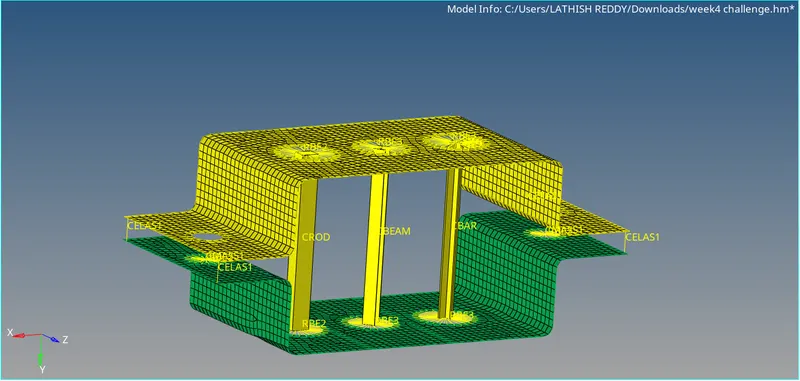
a. Rod element:- Translational DOF should be Constrained with RBE2 link
Cross-Section: BOX- Dimension a= 12 mm
dimension b=10 mm
Thickness t= 0.75 mm
b. Beam element:- All DOF should be constrained with RBE3 link
Cross-Section: I Section- Dimension a= 8 mm
Dimension b= 10 mm
Dimension c= 8.5 mm
Thickness t1= 0.75 mm
Thickness t2= .6 mm
Thickness t3= .6 mm
c. Bar element:- Constrain only x and y DOFs With RBE3 link
Cross-section: X section- Dimension DIM1= 5 mm
Thickness DIM2= 1.2 mm
Dimension DIM3= 10 mm
Thickness DIM4= 1.2mm
d. & e. Apply the mass of magnitude 10 with the RBE2 link
f. Join the two components with Spring elements
PROCEDURE:
- Open hyperworks and select Optistruct as user profile.
- Import 'PARALLEL_BRACKET.IGS' from import geomery option and click import, to display the component on to the work page.
- Go to mid surface tool to create mid surface of the given component from geometry option.
- From there choose OFFSET option available in extraction option, so that it will capture the edges of the given component well. Then select one surface of the component and click extract.
- Rename the mid surface component as bracket 1 and create one more component by right clicking the mouse buton and click create option from component title and rename it as bracket 2
- Now select other surface of the component and click extract
- In order to move the mid surface (created last) to bracket 2 , Go to organize tool from tool option and select the surface
- Delete the solid part from delete option and also delete the 'parallel_bracket' component so that mid surface can be vie
- Create material and property for the components and assign suitable card image (PSHELL) and thickness and update it in components list accordingly
- A washer split is made around the circle to capture the geometry well.
- Mesh the component (f12) with an element size of 8mm, element type as quad and adjust the number of nodes to align.
- RBE2(Rigid) and RBE3 elements are craeted from 1D option by specifying nodes and DOF. Tick the DOF coloumn box, where montion is to be consrtrained
- Hyper beam is used to create the cross sections for beam, bar and the rod
- Create new cross section from the Hyperbeam window by right clicking and choose optistruct and from there select the cross section that are needed and rename it accordingly
- To assign property to the cross section, create new properties and and edit the card image and beam section.
- Update the information in rods and bars tool to assign the property for rods, bars and beam respectively.
- Go to the 1D detail element representation to view the cross section created
- Add mass of magnitude 10N from 1D option, Select CMASS1 as element type, select the node and click create
- Create spring elements from 1D options and select the 2 nodes to connect, assign DOF and click create.
- Save the file.
RESULT:
A mid surface has been craeted from the given component and created 1D elements with different types of given cross section and degree of freedom.
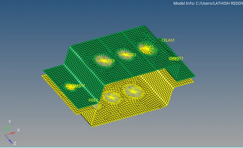
MIDSURFACE MESHING:
1D element with different types of cross section.
CONCLUSION :
From this project, i got the knowledge of midsuface creation and method to use diffetent types of 1D element available in Hyperworks