Assignment 3-2D Element Formulation Challenge
AIM:-
- To run the simulation for a given component with and without changing the recommended element parameters using radioss solver
Objective:-
- Import the crash beam file and change the run time to 55 sec.
- Change the number of animation steps during simulation to a minimum of 25 and a maximum of 60.
- Run the base simulation with default element properties.
- To check the energy error and mass error for the base simulation.
- To polt the graphs and analyze variation for rigid wall force, kinetic energy, internal energy, hourglass energy, contact energy, and total energy.
- Then again run the simulation with change in elements parameter according to given in the challenge.
- To plot graphs for the 2ndd case also and compare with the first case.
Hourglass:
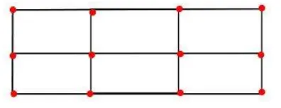
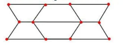
"Hourglass is a deformation, that is noticed when an element is deformed due to the applied load. But the strain energy due to this deformation is not recorded for that element". It is also known as "Zero energy deformation modes" where an element is seen deformed.
- It indicates instability.
- It is also said to be as, non-physical mode of deformation, that occurs in reduced or under integrated elements & produces no stress.
- Usually, it can be seen in the post-processing stage, where the elements will have zig-zag formation.
BEFORE HOURGLASS EFFECT
AFTER HOURGLASS EFFECT
METHODS TO CONTROL THE HOURGLASS:-
- Perturbation method(viscous method)
- Physical stabilization method (stiffness method)
Perturbation method(Viscous method):-
- This method is generally used for the elements with Ishell: 1,2,3,4 or Q4 elements
- The process of how this method work is: When the hourglass deformation occurs---> There will be some damping applied, which is stabilizes the deformation, which results in controlling the speed of deformation.
- But this damping opposes only the velocity, But not the force. So, the force is introduced, which results in adding some stiffness to the elements. This stiffness helps in controlling the hourglass.
- The force is applied externally, by some other means. But not from FEA nature. This force constitutes energy called "Hourglass energy", Which is artificial energy(neither Kinetic nor internal energies). It is a loss of both energy types.
- If the hourglass energy is added along with the kinetic energy & Internal energy, A balance system is obtained.
- Recommended for high velocity or high strain rate problems. Example: Involving high explosives.
- A huge amount of hourglass energy is generated.
Physical stabilization method (stiffness method):-
- In this method, the stiffness is getting added right from the material level. This will have a large effect on our component.
- It is recommended for fewer velocity problems.[for less velocity than 1000m/s]
- used for QEPH elements.
- Less amount of hourglass energy is needed. Because it is going to be controlled before it arises.
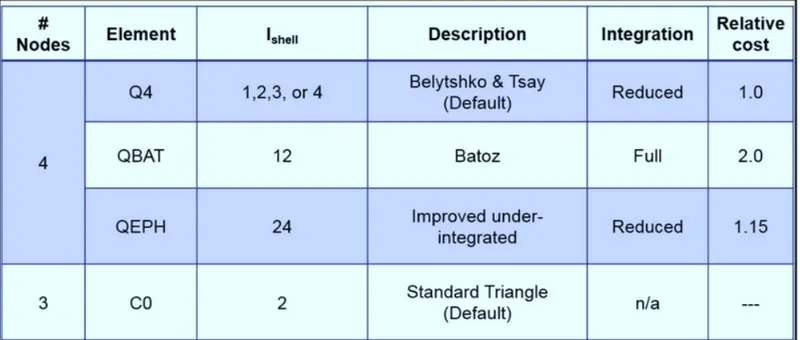
Q4 element:
- It is an under(or) reduced-integrated element. Because it has only 1 integration point for an element.
- It is represented in the radioss solver by an entity named "I shell(1,2,3,4)".
- Usually Ishell:1, Ishell:4 elements are used, when no more velocities are to be found.
- By default, the solver takes as Ishell:1.
- As it has only 1 integration point, the time required to solve the problem with this type of element is relatively less.
- The cost required to solve this type of element is relatively low.
- But there will be no accuracy in the results.
QBAT element:
- It is a fully integrated element, Which means it comprises 4 integrated points. Each point is near to each node.
- It is represented in the radioss solver by an entity named "Ishell: 12".
- Because of these 4 Gaussian integration points, there will be no Hourglass deformation.
- Using this element is not economical. But the achieved results are more accurate than the remaining Ishell elements of quads.
QEPH element:
- It is an improved under-integrated element with physical hourglass stabilization within itself.
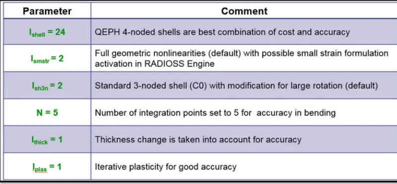
- It is represented in the radioss solver by an entity named "Ishell:24".
- This type of element is mostly used recently. Because of its best compromise between the cost, quality& accuracy in results.
- It is widely used in the automotive industry.
CO element:
- It is a standard co-rotational triangle, with modification for large rotations.
- Usually, it helps in representing the tria elements with the entity named "Ish3n:2".
- It consists of 1 integration point.
- No hourglass deformation.
- Low CPU cost.
The key parameter for shell elements-
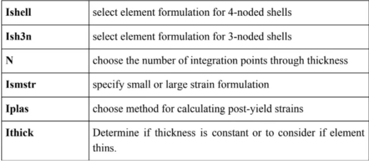
Recommended parameter for shell elements in Crash-
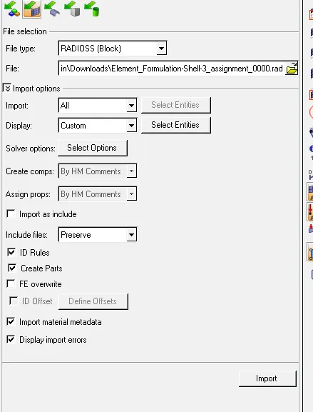
- Here switch the file type Radioss block and then select the file which need to import. After importing the file go to the model browser and check for cards.
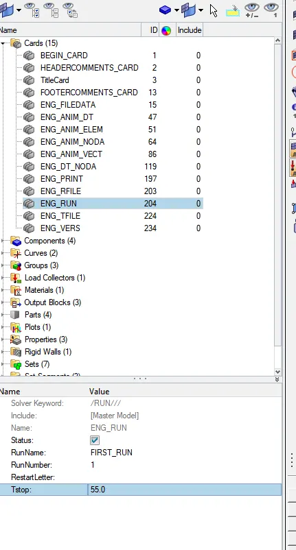
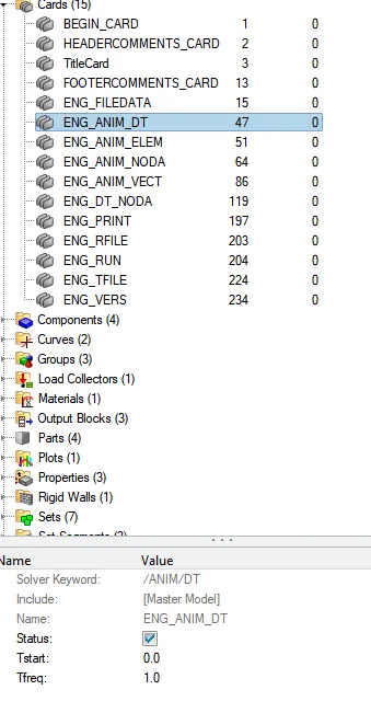
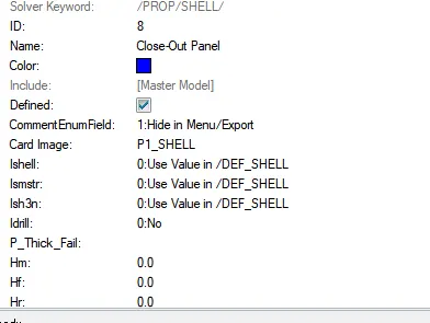
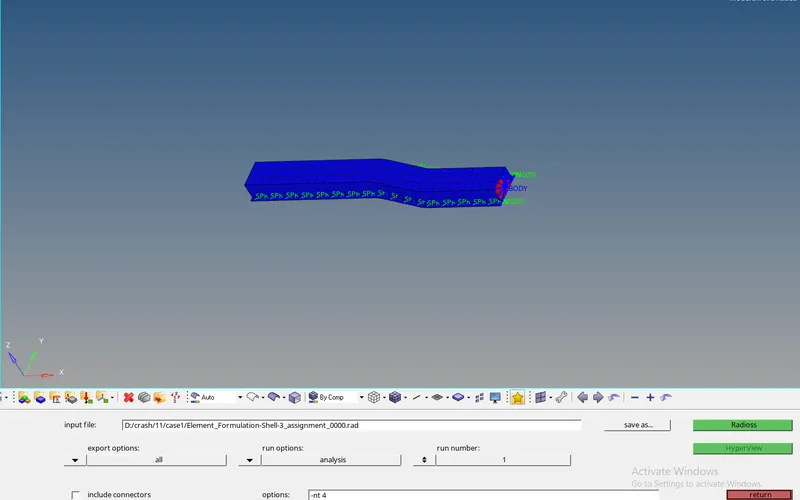
- Then save this 0000.rad file as the desired location named as case -1.
- After that click on Radioss it will start the simulation. And wait untill the new window popup and show as Radioss job completed
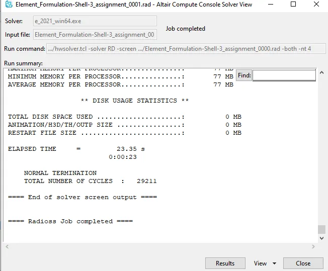
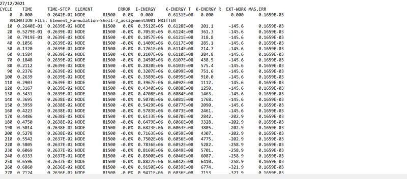
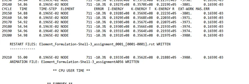
- Maximum energy error= -10.3 Acceptable (Range is -15% to +5%)
- Maximum internal energy error= 0.1932 x 10^8
- Maximum kinetic energy error = 0.3563 x 10^8
- Maximum Mass error = 0.1695 x 10^(-3) Acceptable (Range is 0 to 2%)
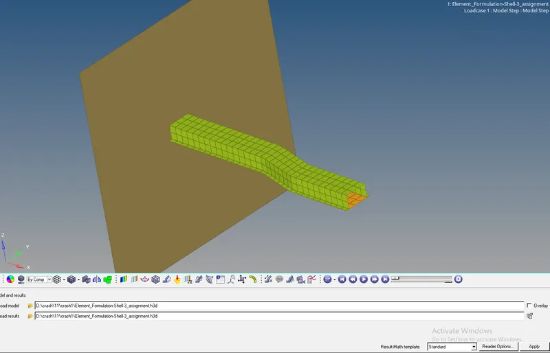
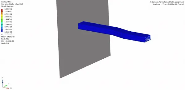
- Now split the window in 3Part and open hypergraph-2D in the new window.
- After opening the hypergraph window import the T01 file in Hypergraph.
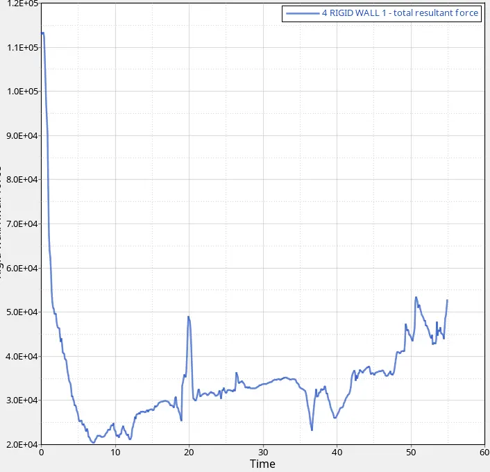
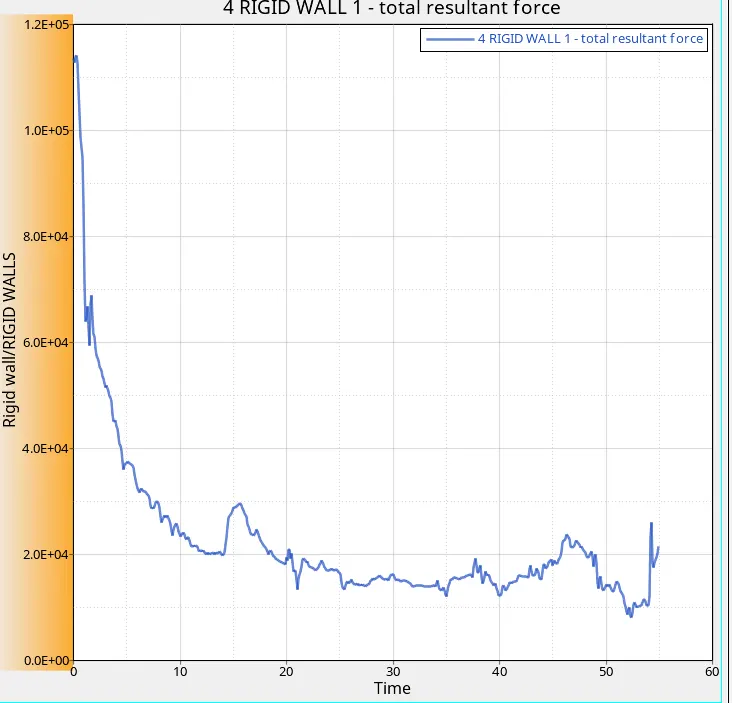
- Rigid wall force is the force exerted by rail elements to the rigid wall.
- Initially, it was higher but due to internal deformation in rails, the applied force on the rigid walls start decreasing.
- Initially, force is higher in the graph because the initial point shown in the graph is the moment when rail hits the wall and at that moment Rigid wall force was high. There is a significant amount of force which started getting converted into frictional force so we will plot frictional force also.
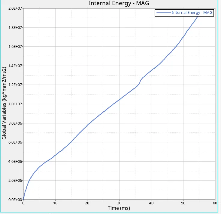
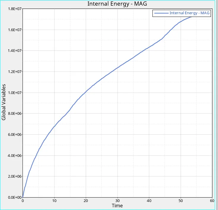
- At t= zero internal energy also zero then gradually increases
- Internal energy I= Q + W
- We can neglect Q there is no heat transfer
- W= F X D
- Internal energy increases due to deformation that occur
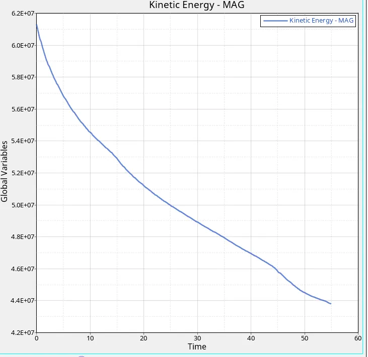
2. Kinetic energy
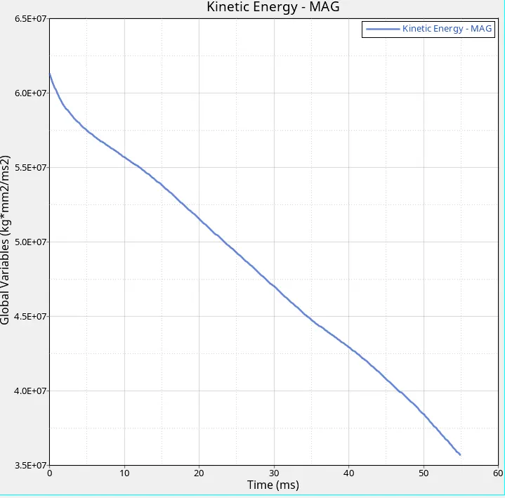
- kinetic energy decreases from t=0 to end
- It decreases due to decreases in velocity after the initial moment
- Where rail start deforming sp there will be an energy restore
- At the end of deformation kinetic energy value become zero
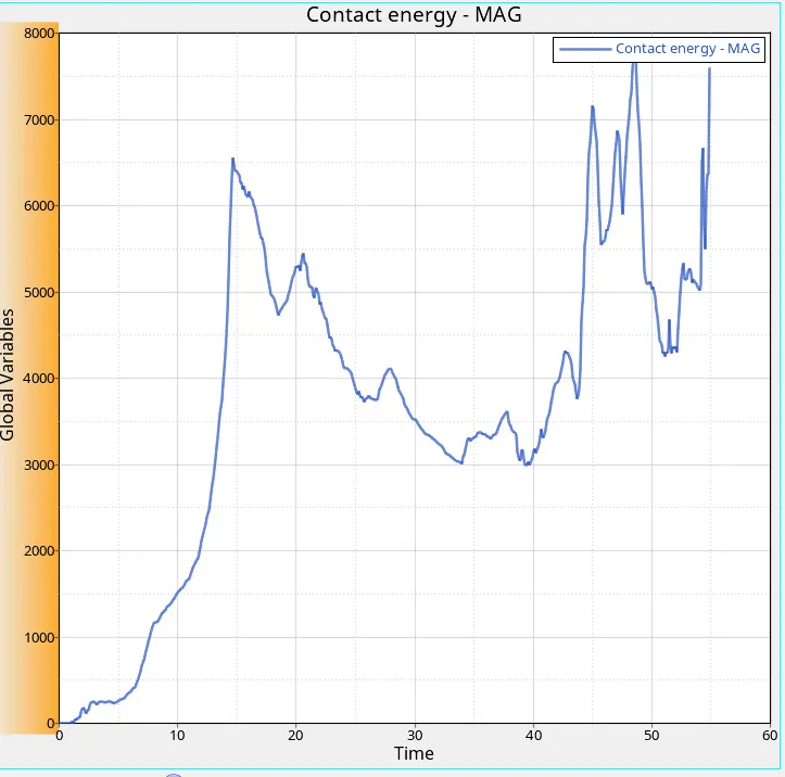
3. CONTACT ENERGY:-
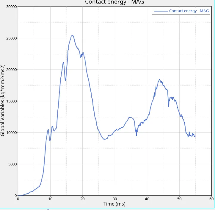
- Initial there is no contact energy because there is no self contact the component
- when the component starts hitting wall contact energy increases
- when displacement or deformation occurs contact energy increases
4. Hourglass energy
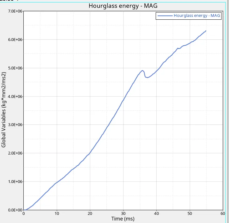
- Here hourglass energy starts from the initial position because no recommended parameter is applied
- To balance rest energies hourglass we need artificial energy called hourglass energy and goes increasing
5. Total energy
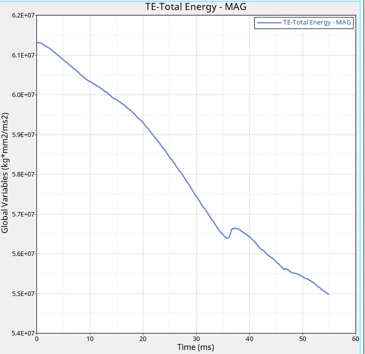
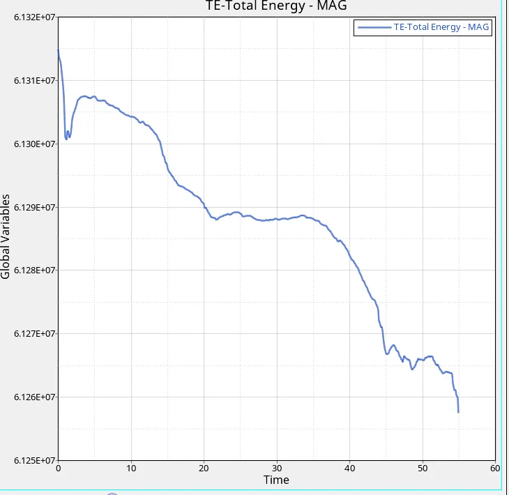
- Total energy = sum of KE+IE+CE+HE
- Initially, it is in increased condition because it is the sum of all energies
- Only kinetic energy is increased value in the initial position
- Kinetic energy is directly proportional to total energy
Case-2:-
Assign recommended parameter to property card-
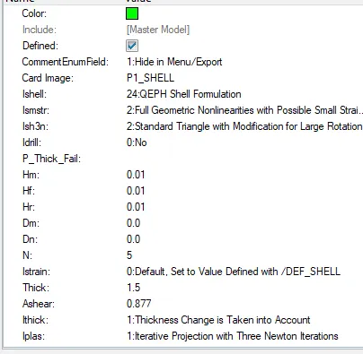
- Now follow the same procedure for engine file edit as we did for case-1.
- And then run the model.
Now check for energy error:-
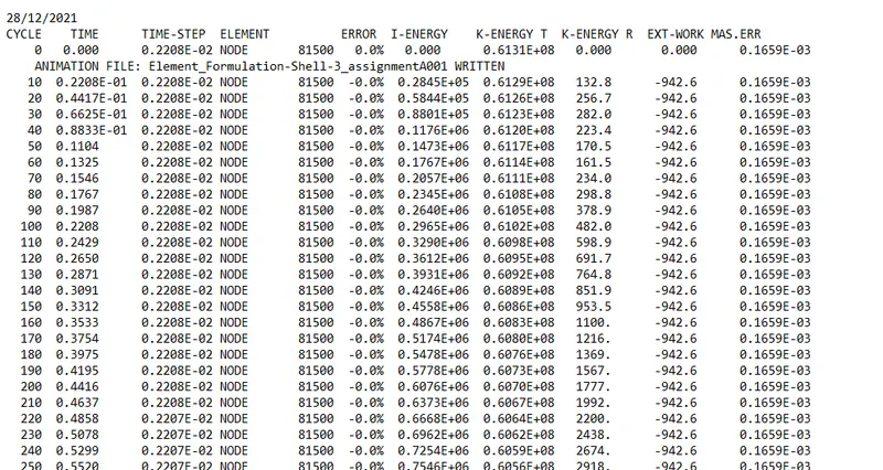
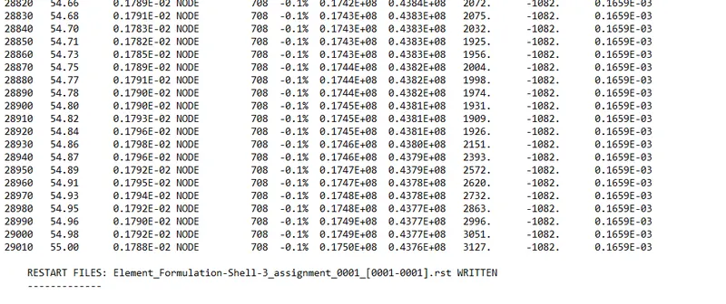
- Energy Errors are in an acceptable range
Simulation in Hyperview:-
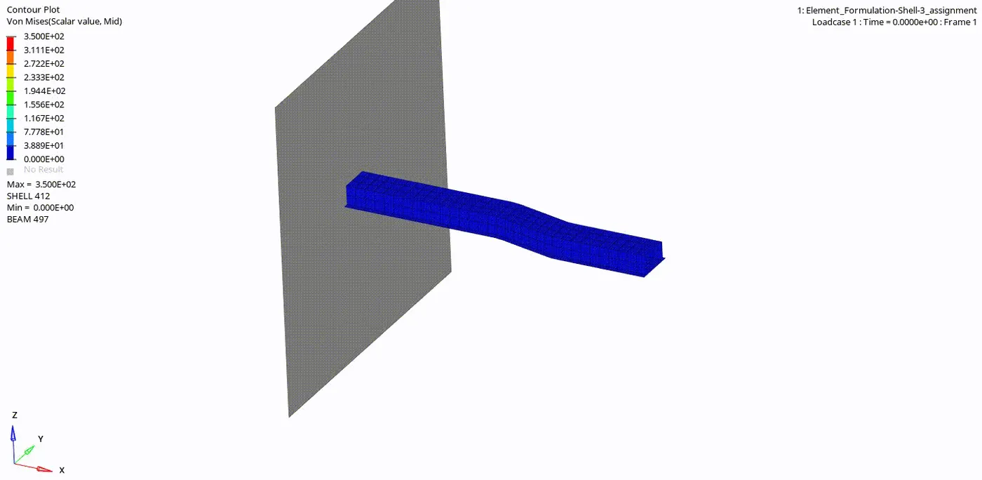
1. Internal Energy Graph:-
2. Kinetic energy:-
3. CONTACT ENERGY:-
4. Hourglass energy:-
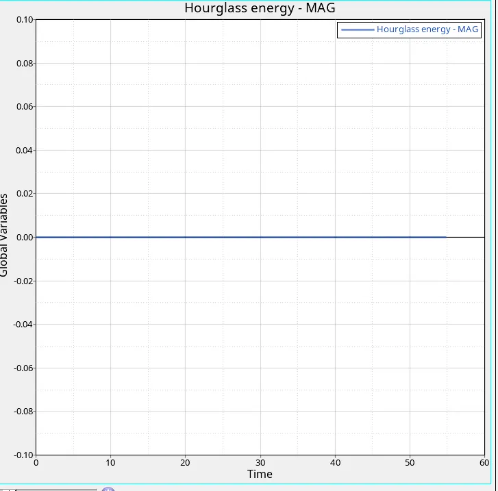
- Here no hourglass is because the use of the recommended properties
5. Total energy:-
6. Rigid wall forces:-
comparison of case-1 and case-2
| Characteristics | Case-1 | Case-2 |
| Maximum energy error | 10.3% | -0.1% |
| Maximum kinetic energy error | 0.3562*10^8 | 0.3970*10^8 |
| Maximum internal energy error | 0.1933*10^8 | 0.2156*10^8 |
| Total energy error | total energy increases and slightly decreases due to energy error | no change in total energy |
| Hourglass energy error | hourglass energy increases due to all other energies | energy remains constant due to applying recommended parameter |
Result-
- Run time and amination file are updated in the solver file.
- Simulation has been run without assigning recommended parameters.
- Graphs are plotted for case-1.
- Simulation has been run with assigning recommended parameters.
- For the 2nd case also graphs are plotted and both cases are compared in terms of energy variation.
Conclusion and Learning outcome-
- In this assignment, I learn the engine file creation for a simulation run.
- Then how to perform postprocessing like plotting graphs for energies.
- And also how to see the animation of simulation in hyper view.
- Then How to assign the recommended parameters and understand their benefits in controlling the hourglass.
- How to check the graph variation for both the cases and conclude the better one.
- From this assignment according to me simulation with assigning the thickness is a better choice which is case-2