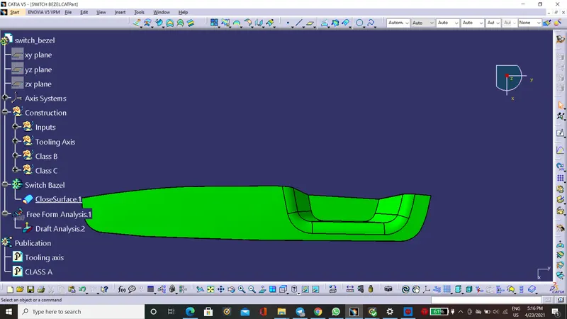
Week 8 - Challenge 3 - Switch Bezel Design
Draft: Draft is given for the easy removel of the finished product
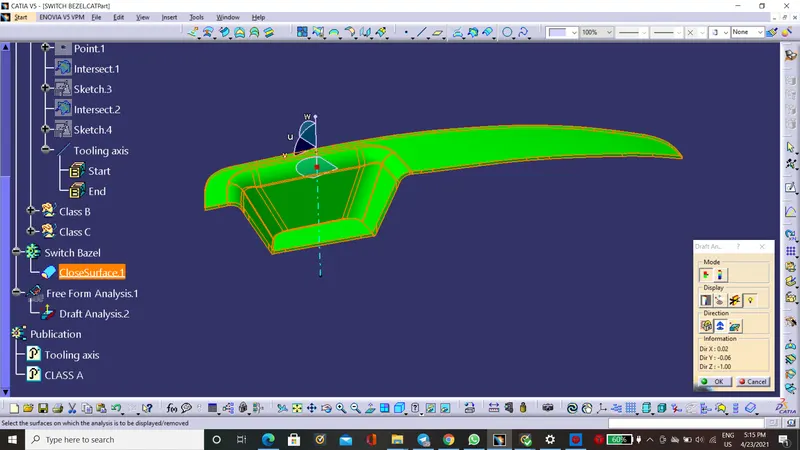
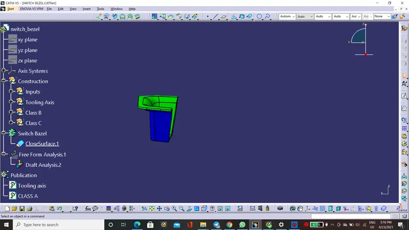
Draft Analysis: It is the tool used for cheack the if the drafted design is manufactuable or not.
Steps for Creation of Tooling Axis:
1. Extract the bottom Face, And cteate point on centre of it.Then add axis sytem on the point.
Use intersect for Class A And the YZ plane of axis. Next use positioned sketch in yz plane.
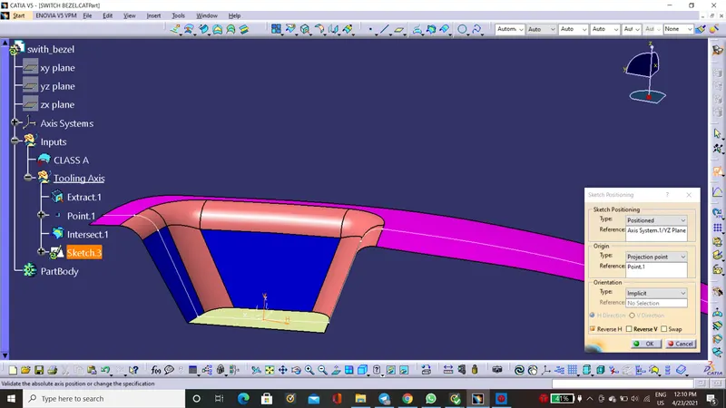
2. Create A toolig axis in the Y diection whith help of positioned sketch in which create two line on the inclined surface then bisect them.
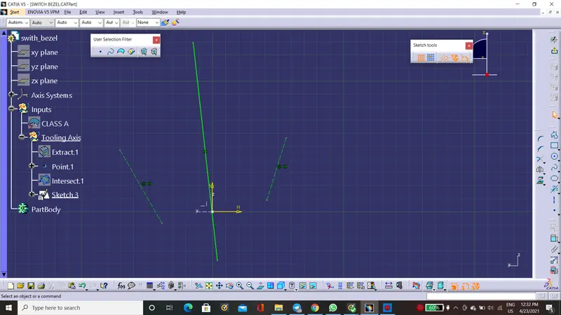
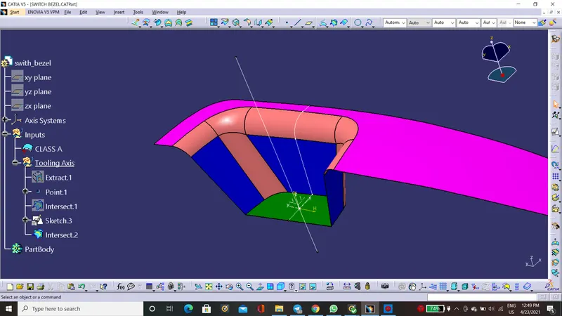
3. Intersect ZX with the class and Create the tooling Axis in X direction with by biecting line on the incline surface and the line 8 degree from inclined surface line.
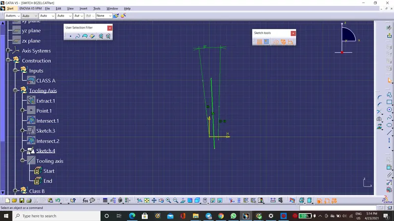
4. Bisect these two lines from sketch And increase lenth of it and name it as Tooling Axis. Then Publish the tooling Axis and class A surface for convinience.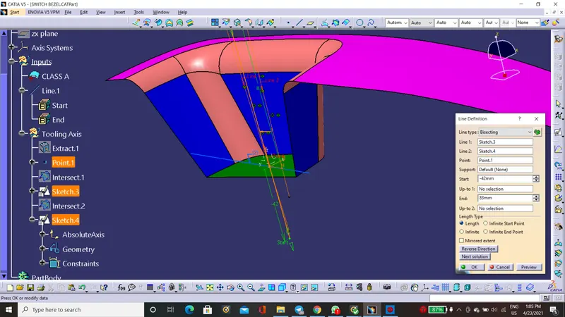
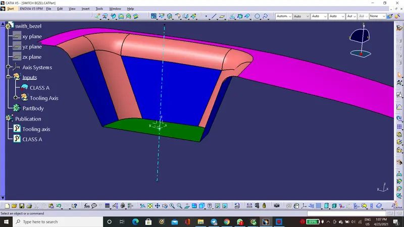
Steps for class B creation:
1. First Exract the wall surface without fillets (fillets cause problems) And untrim them.
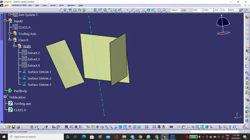
5. Extrpolate these surface for trimming and after extrapolate trim them as required
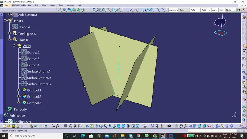
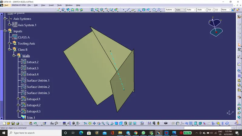
6. Offset this by 2.5 mm because thickness of the part is 2.5mm.
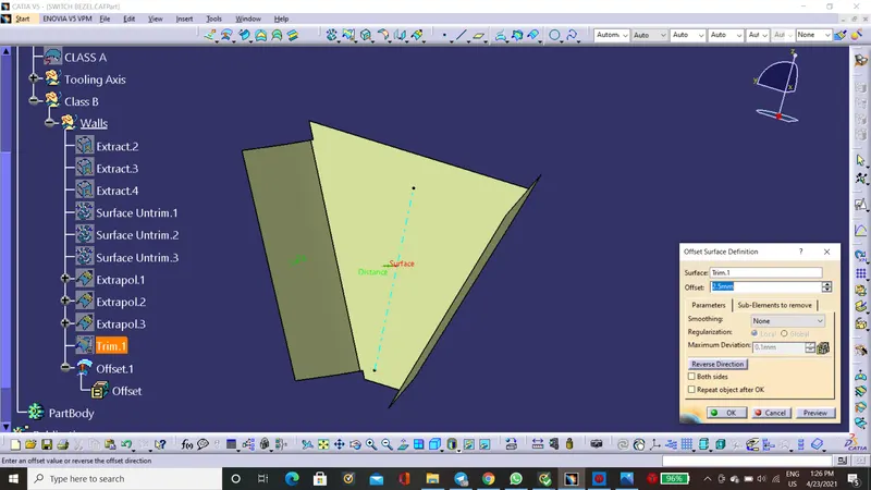
7 Do the same procedure for top and bottom face.
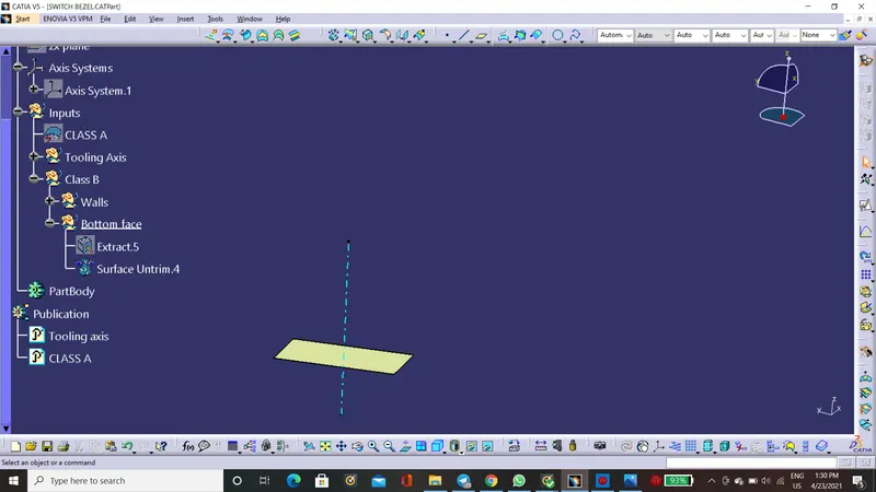
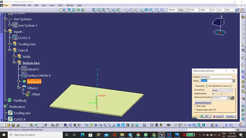
For top face
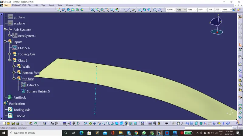
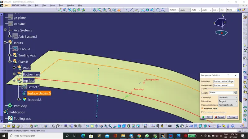
8. trim these 3 and will get the class B surface.
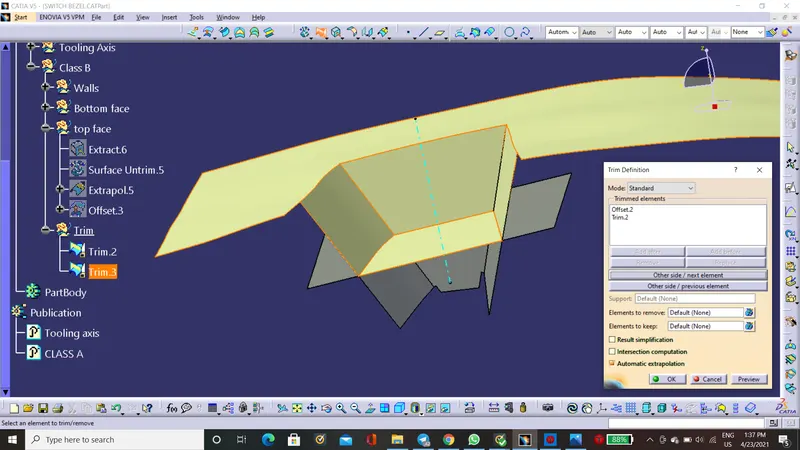
Class C Creation
1. Use Extract all And extract rhe boundry of class A surface
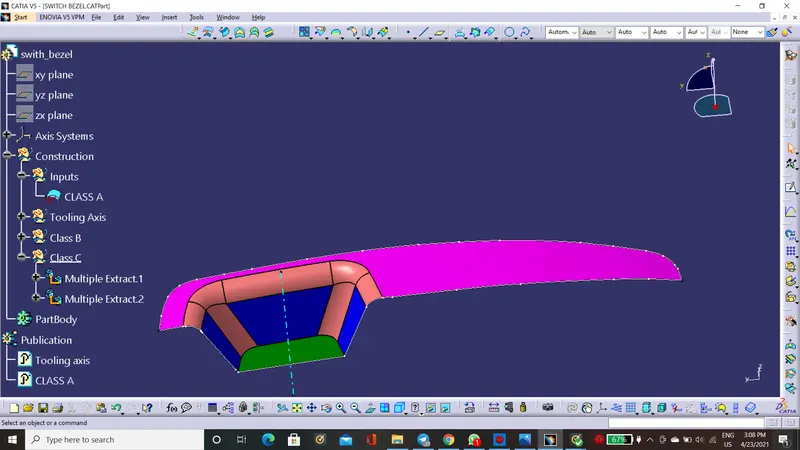
2.Apply smooth curve on it.
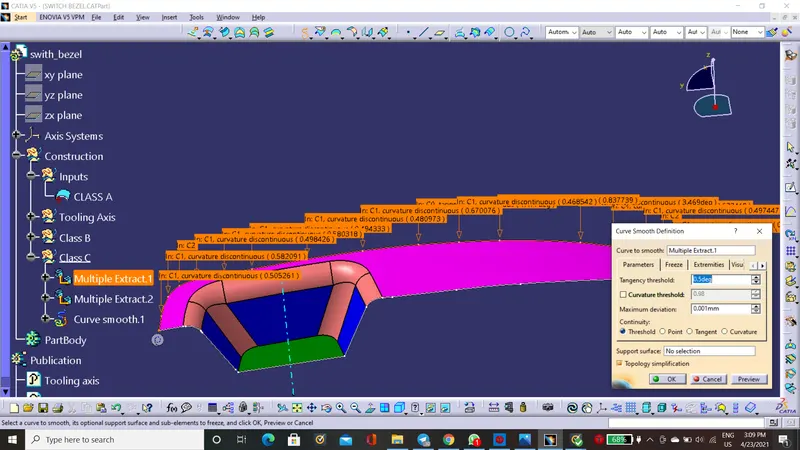
3. Sweep Thses cuve with the tooling axis
Draft direction should bee outside.
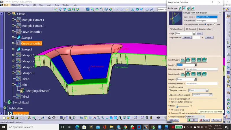
4. Extrapolate the edges and trim it
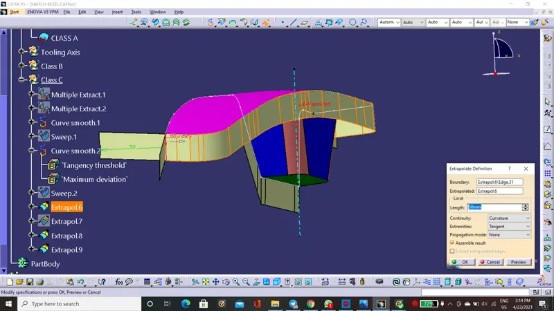
5. Join the Class A with this trim
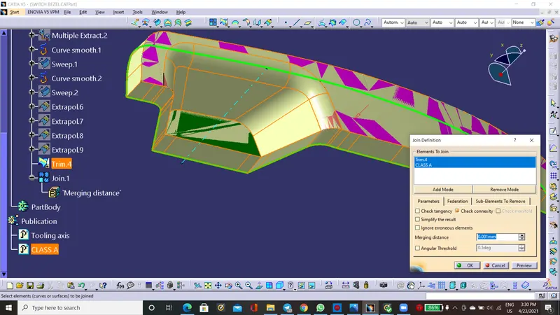
6. Trim Class C Suface Witch Class B And this will be the final step of sufacing.
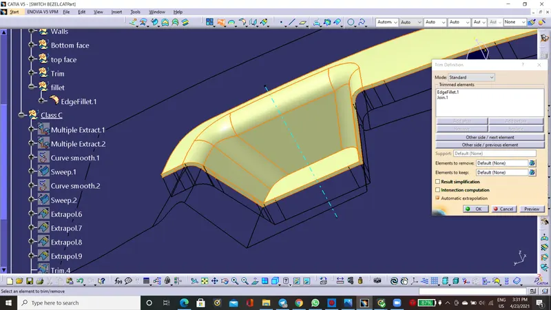
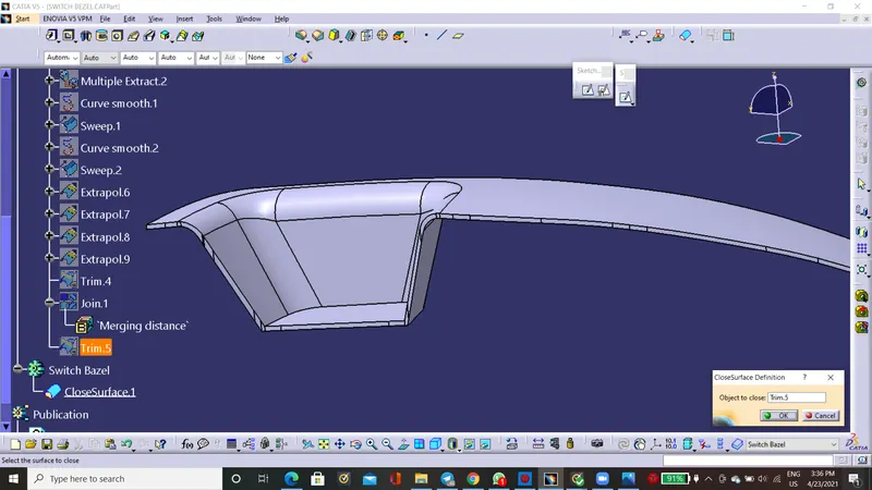
Solid Body Creation:
1. Oen part bosy workbench Inthis choose closed suface tool and give that to final trim
Hide the Last trim we will get the solid body of switch bazel
Draft Analysis if class A
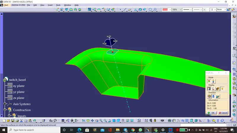
Draft Analysis of the final plastic product
Different views of final product:
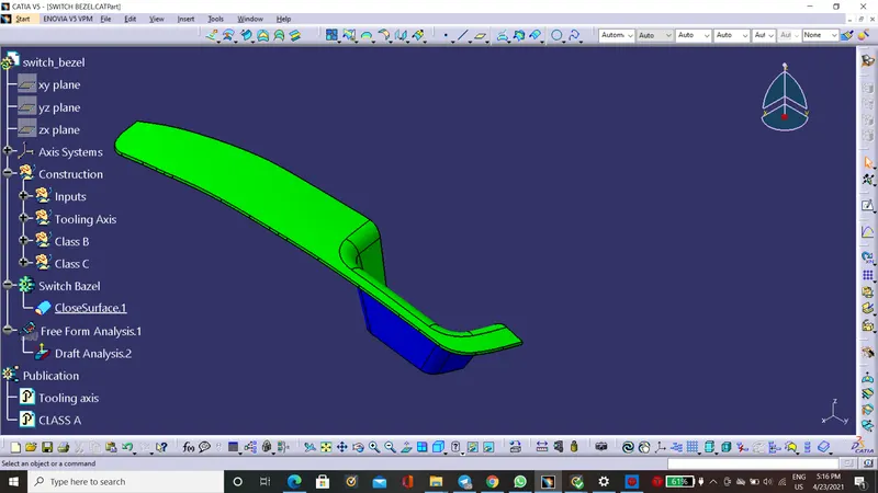
Isometric View:
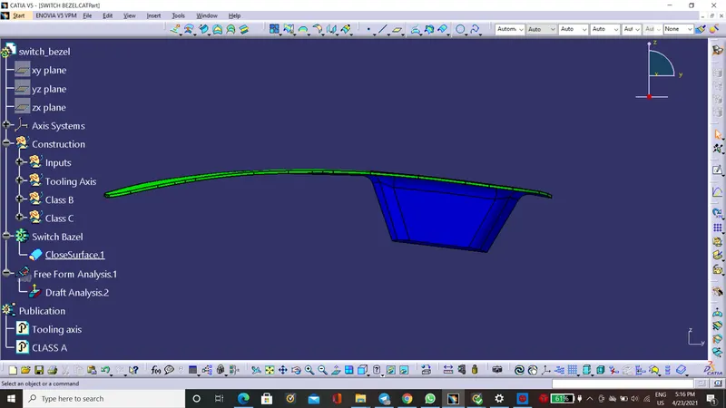
Front view
Left view
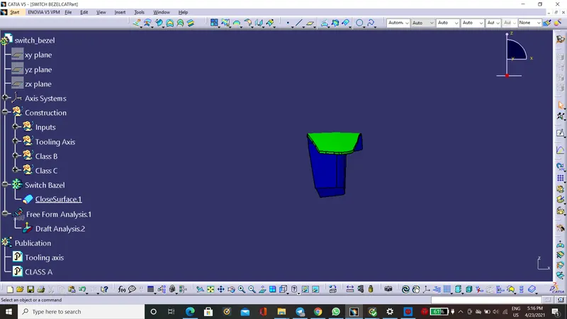
Right View:
Top view: