ASSIGNMENT 2- Perform 3D meshing on component according to given criteria and edit the engine files of RADIOSS.
OBJECTIVE:- To 3D mesh the component according to given criteria and calculate the problem from starter file and edit the engine file.
1. Check the material properties of the rail component and calculate the speed of sound in steel rail.
- Open Hypermesh and import the solver deck file FIRST_RUN_0000.rad.
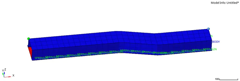
- Under the model tab -> material there the material properties can be found
E= 210000
`rho`= 0.0078
`nu` = 0.29
Speed of sound can be calculated by, c = `root``(E/rho)` = `root`(210000/0.0078) = 5188.745 mm/ms
2. The length of the rail is about 1000 mm. calculate the time takes for a shock wave to travel from one end of the rail to the other.
Time taken by shockwave to travel 1000 mm, `Delta t = l/c = 1000/5188.745 = 0.1927 ms`
3.Time for sound to travel the length of the rail is 0.1927 ms.
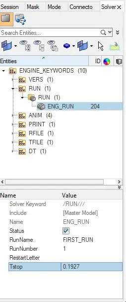
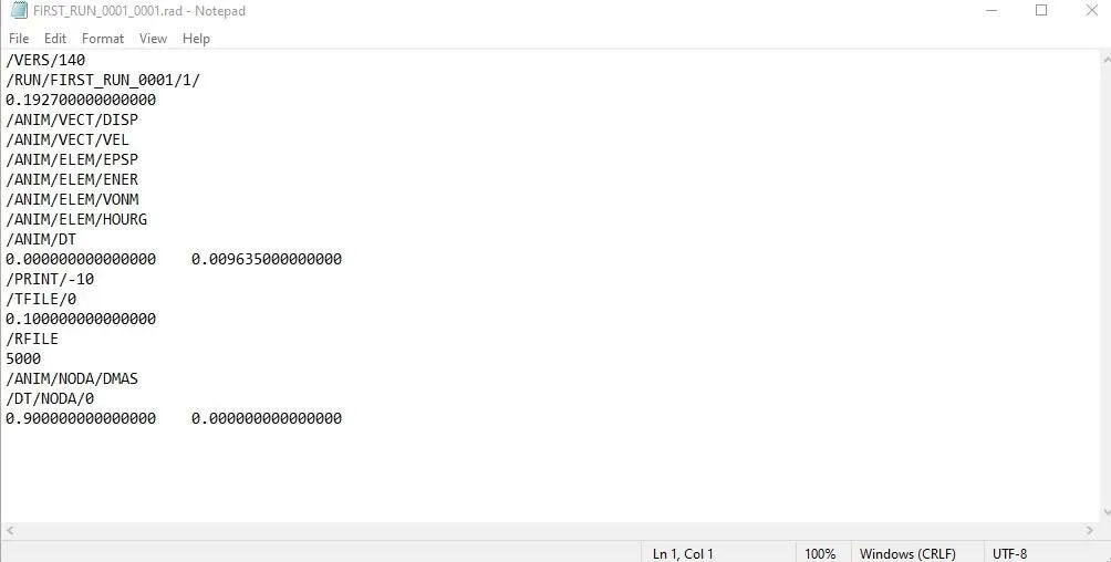
4.Edit the engine file so that the stress wave can be monitored, moving from one end of the rail to the other during an impact -this will require a termination time equal to the time it takes for the sound to travel the length of the rail(set on/RUN card)
- Open Hypermesh and import the solver deck file FIRST_RUN_0001.rad which is the solver file.
- In the menu bar, goto view -> browser -> hypermesh -> solver
- In the solver tab under entities change the ENG_RUN -> Tstop = 0.1927
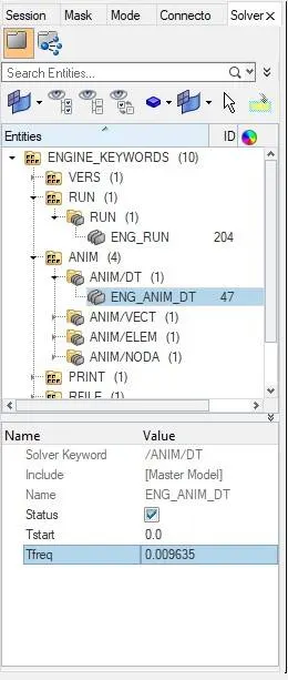
5.Set the frequency of animation output to a time that will give 20 animation steps(/ANIM/DT)
- Change the "/ANIM/DT" -> `Tf req = 0.1927/20 = 0.009635`
6.Change /print -10.
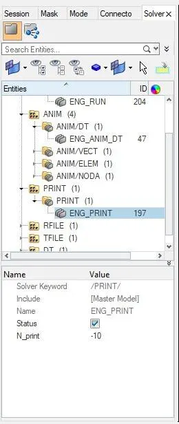
- After saving the change made to the engine file, the file can also be view on just opening the file as notepad.
7.3d meshing tetra mesh and hex mesh
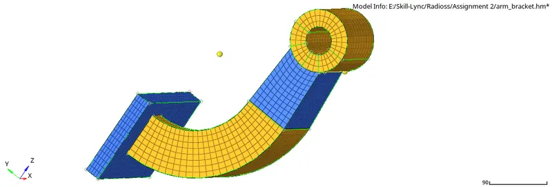
(I) Hexmeshing the arm for hex size = 10mm
- Open hypermesh and open the ".hm" file
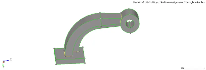
- Check the component for any error.
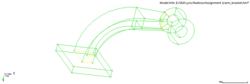
- As there is no error, next set the target size as 10 under criteria file setting and under 2d -> automesh -> surface -> element size = 10, mesh type = quad -> mesh the base surface of the arm
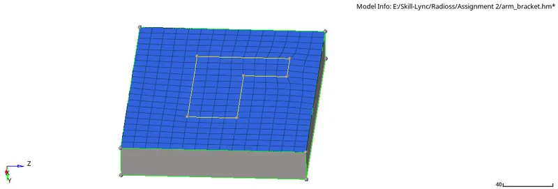
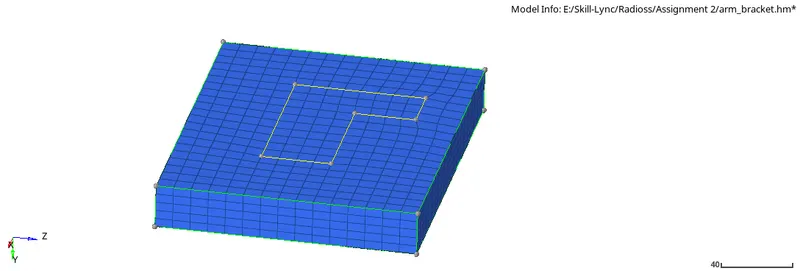
- Now to create solid hex mesh, under 3D -> element offset -> solid layers -> 2D elements to offset = elements = select the elements -> along geom to follow = surfs =select the edge surface of the base -> number of layers = 5 -> total thickness = 25 -> click on offset+ve
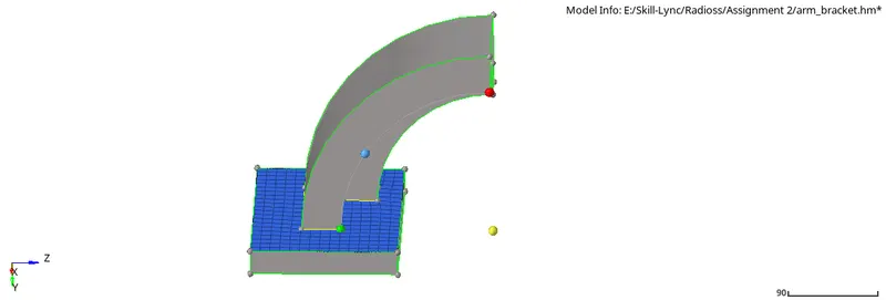
- Before meshing the "Arm curve" mask the hex elements and also create a centre node using the circular edge of the arm, now under 3D -> spin -> spin elements -> select the 2D elements covered under the arm curve area -> select x-axis and centre node as the base node -> angle= 90 -> on spin = 25 -> spin-ve
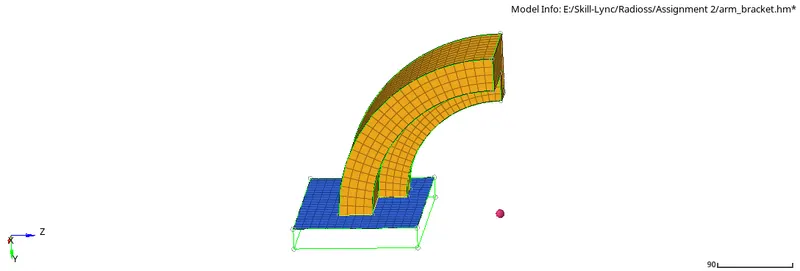
- Before generating mesh on the "arm straight", generate 2D quad mesh on the face connected to the boss and using the Face option under Tool generate face elements from the arm curve.
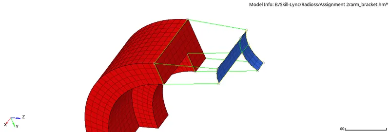
- Now under 3D -> Linear solid -> from = elements = select face elements -> to = elements = select the 2D quads -> select both the alignment nodes N1, N2 and N3 such that the source and destination should match -> density = 12 -> solids.
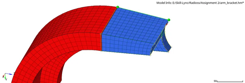
- Delete the face elements.
- To mesh the boss first generate 2D quad elements on one side of the boss such that the number of elements present on the arm straight should also match the number of elements present on the side of the boss connected to arm straight, also by using Project option under Tool, project the node of the arm straight to the surface of the boss which will represent the true normal.
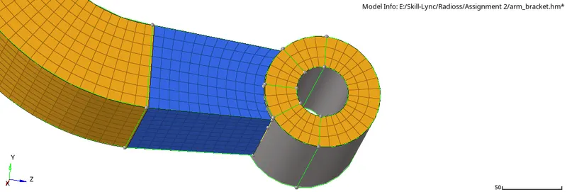
- Now under 3D -> Solid map -> general -> Destination geom = surface = select the bottom of the boss -> Along geom = mixed = select the node path and line connecting the top of boss to bottom -> Elements to drag = elements = select the top elements of boss -> Along parameter = elem size = 12 -> mesh.
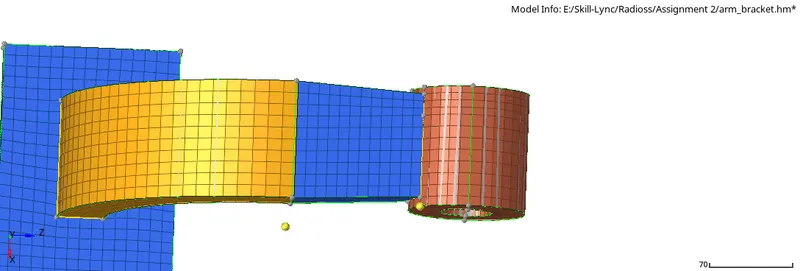
- Delete all the 2D quad elements.
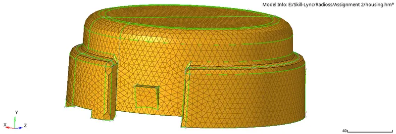
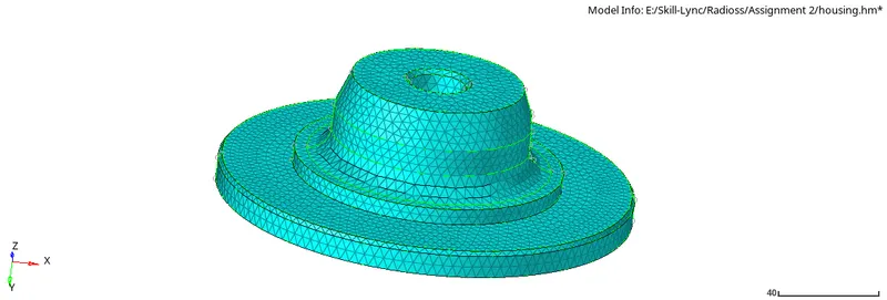
(II) Tetra meshing on housing, target length is 5mm and tet collapse = 0.15
- Open hypermesh and open the ".hm" file. There are 2 component cover and hub.
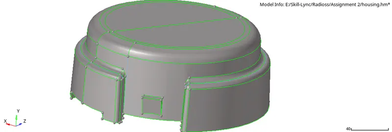
- Before meshing set the criteria file setting to target 5mm and tet collapse 0.15.
- Under 3D -> Tetramesh -> Tetramesh Parameter (provide min. size = 5mm and tet collapse = 0.15) -> Volume tetra -> Enclosed volume = surf (select the cover entity) -> 2D type = trias -> 3D type = tetras -> Element size = 5 -> mesh.
- After tetra mesh generation check for tet collapse by, Tool -> check element -> 3D -> tet collapse.
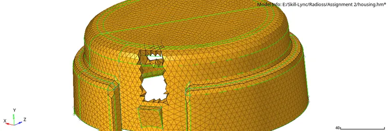
- For the hub as it already has tria elements, tetra mesh can be generated by 3D -> tetramesh -> tetra mesh -> fixed trias/quads to tetra mesh = elements -> mesh
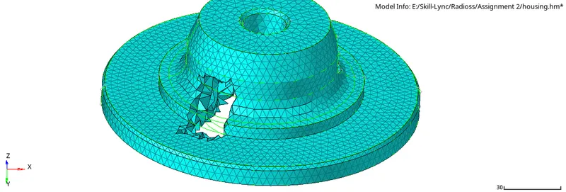
- After tetra mesh generation check for tet collapse by, Tool -> check element -> 3D -> tet collapse.
Result:-
Conclusion:-
So by completing this challenge, I learnt how to 3D mesh a component in different ways and how to edit the engine files of RADIOSS.