Assignment 1-2D Meshing Challenge in Hypermesh.
Aim:
To Mesh the given sheet metal Models.
Model 1
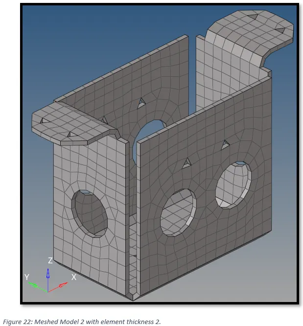
Model 2
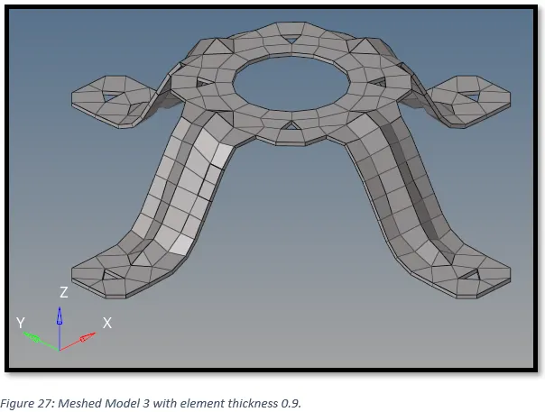
Model 3 (Mounting Bracket)
Objective:
- Clean the geometry.
- Extract mid-surface.
- Clean mid-surface geometry.
- Ignore holes less than Dia 5mm.
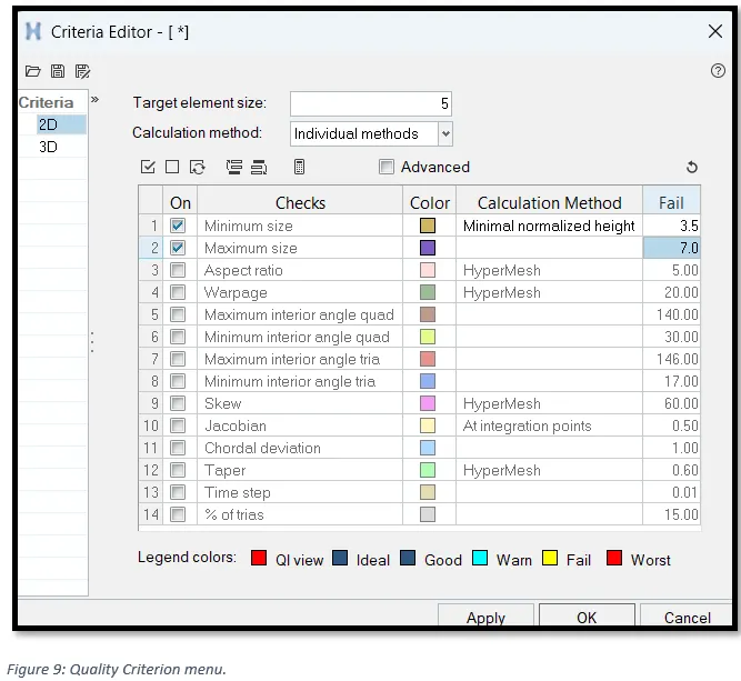
- Create 2D mesh with target length 5mm, min 3.5mm max 7mm.
- And assign proper thickness, by creating a generic property.
|
Sl. No. |
Quality Criteria |
Value |
|
1 |
Target/Average length |
5mm |
|
2 |
Minimum Length |
3.5mm |
|
3 |
Maximum Length |
7mm |
Introduction:
Meshing (nodes and elements) is nothing but the discretization of a continuous system (a model or a geometrical shape) with infinite degrees of freedom to a finite degree of freedom.
A mesh is made up of nodes and elements. A Nodes are limited number of points where calculations are made. The entity joining nodes and forming a specific shape such as quadrilateral or triangular is known as an Element.
Procedure:
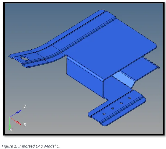
1) Importing the CAD model.
To make the edges coloured according to their topology status switch to 2D Topo view. To know what the colours mean, click on the ‘visualization’ option.
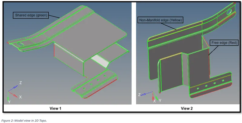
From Figure2, we can observe that the model consist of surfaces and no solids. The edges of the surfaces are coloured green and red. Edges that are coloured green are shared edges. A shared edge is an edge that is owned, or shared, by two adjacent surfaces. When the edge between two surfaces is a shared edge (this is what you typically want to have), there is no gap or overlap between the two surfaces - they are geometrically continuous. The automesher always places seed nodes along the length of a shared edge and will produce a continuous mesh without any gaps along that edge. The automesher will not construct any individual elements that cross over a shared edge.
Red colour depicts free edges- they show where we might have missing connectivity or gaps. A close loop free edge shows a hole or a missing surface.
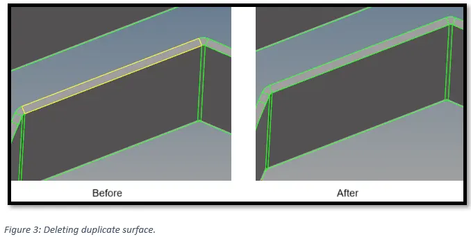
Yellow colour depicts non-manifold- they show edges where more than two surfaces share an edge. Which might be a T-connection or a duplicate surface.
Blue colour depicts Suppressed edges. Edges which are suppressed on purpose for some reason.
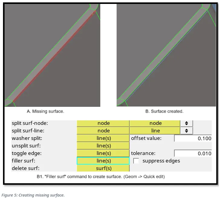
2) Geometric Clean Up of the CAD Model.

3) Extracting Mid Surface.
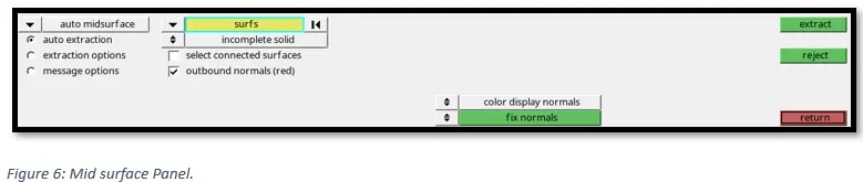
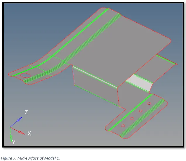
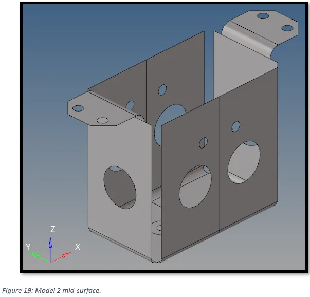
To extract the mid surface of the model, firstly we need to perform the geometric clean-up i.e. simplifying the geometry by removing small fillets, unwanted feature lines etc. This will aid in extracting the mid-surface easily.
Now Go to, Geom -> Mid surface -> select the surfaces -> Click on extract
4) Geometric Clean Up of the Mid-Surface.
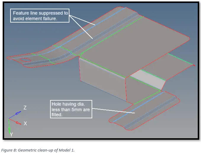
In some areas we may encounter that the feature lines are very close to each other. Since our min length quality criteria is 3.5, elements forming in between feature line separated by a distance less than 3.5 will fail. To avoid this, we may suppress one of the feature lines, keeping in mind there is no major change in the geometry.
5) Setting up Quality Criterion.
In order to avoid deviation from the quality after meshing, we need set up quality ranges.
6) Meshing.
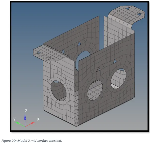
To mesh the Model area by area, go to, 2D -> Automesh -> select all the displayed surfaces & put element size as 5 -> click on mesh.

Now one by one click on the areas to mesh.
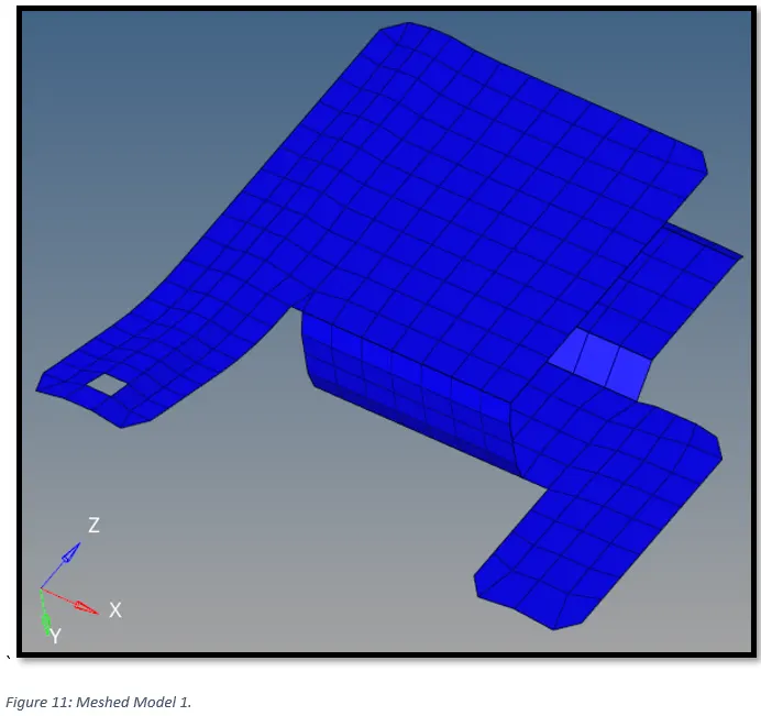
Following rules for should be kept in mind to obtain a good mesh:
- Features should be captured properly.
- Proper Tria Management, i.e., Tria should no touch each other, There should be no opposite trias, Trias near edges and free edges should be avoided.
- Proper Mesh Flow.
- Check if there is any dysconnectivity in the mesh.
- Quality Criteria should be satisfied.
7) Meshed model conforming quality criteria.
To check quality parameters, go to, 2D -> quality index.
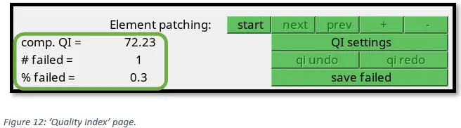
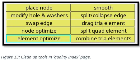
By using clean up tools we can resolve failed elements.
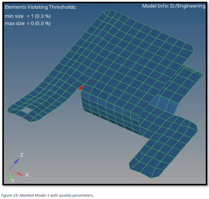
As seen from Figure 14, there is only 1 element which is not conforming to min length quality criterion.
8) Assigning thickness to the Mid-surface.
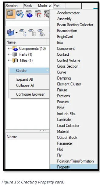
Under the model tab, right click and go to, Create -> Property.
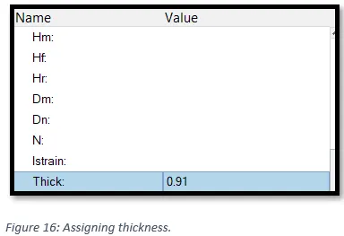
Rename the property card and assign the thickness as per the model thickness. For this model element thickness as 0.9.
Now, right click on the component and click on ‘Assign’ to assign the property card containing element thickness.
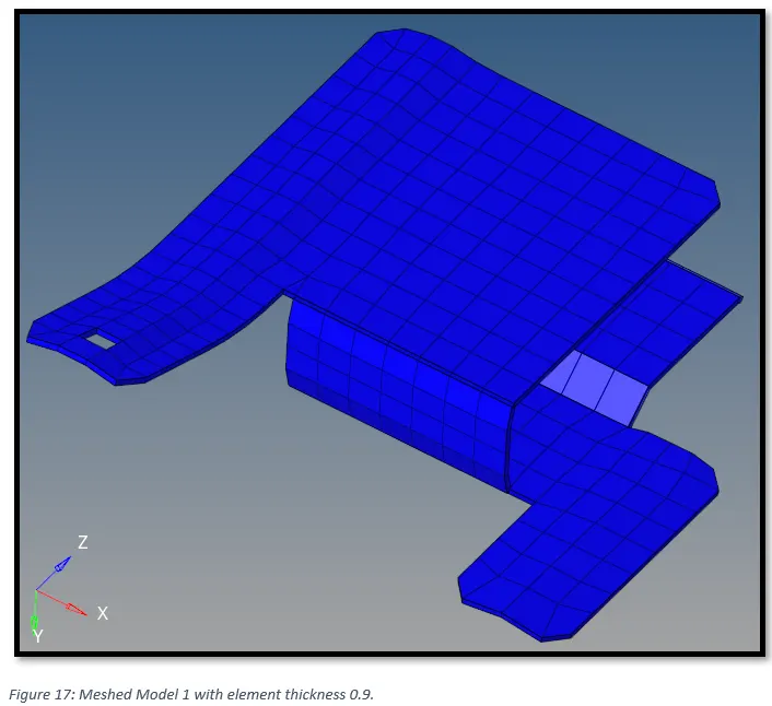
Finally, we can see meshed inner door panel model with element thickness 0.9.
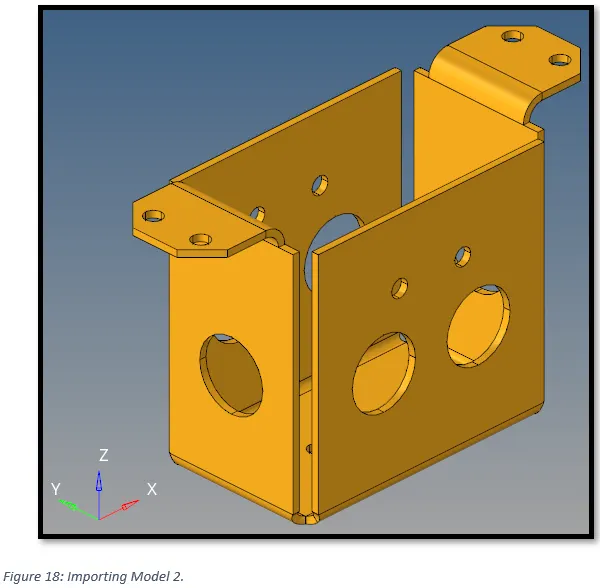
9) Model 2.
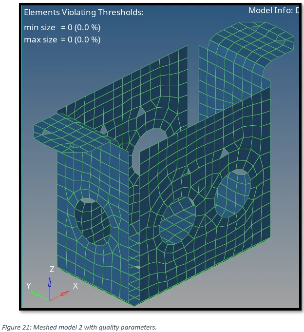
As shown in Figure 21, Model 2 has no failed element.
10) Model 3 (Mounting Bracket).
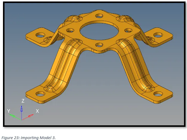
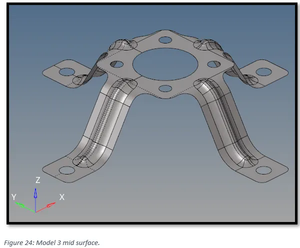
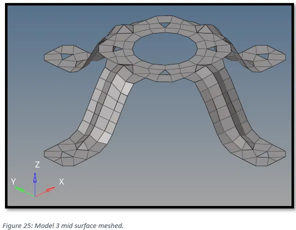
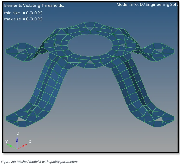
As shown in Figure 26, Model 3 has no failed elements.