SHELL MESH ON SHEET METAL COMPONENT USING HYPER MESH
AIM:- To perform shell meshing on given components.
PROCEDURE:-
- First, we need to import the model in hyper mesh
- Then after we need to check geometrical errors
- Then after we need clear geometrical if present
- Then we need to take mid - the surface of the component
- Then we need to reconstruct the geometry
- Then we need to perform mesh without any quality issues
GEOMETRY CLEAN:-
- Importing the geometry into hyper mesh software.
open hyper mesh software → select preprocessors as Radioss →import → select file → ok
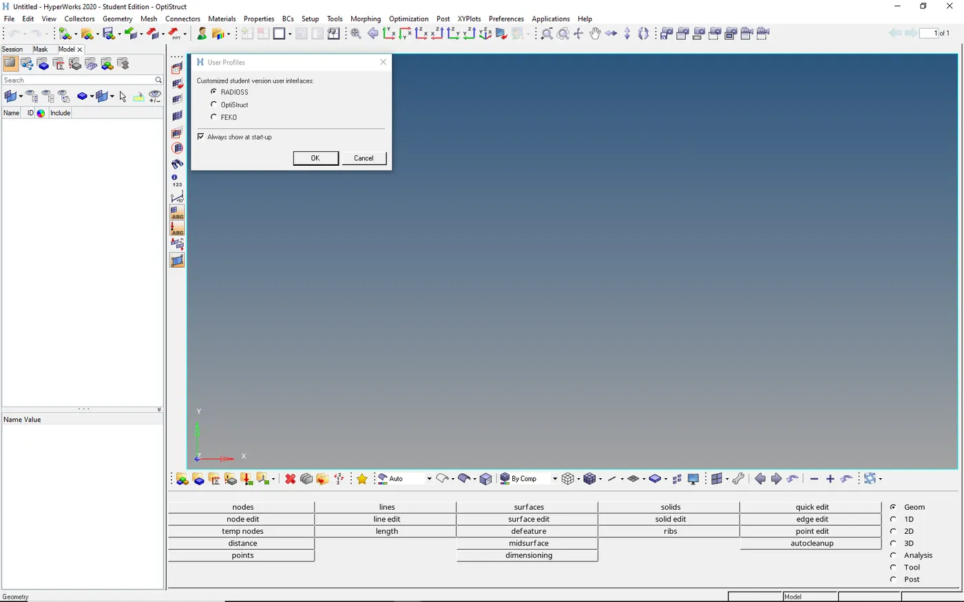
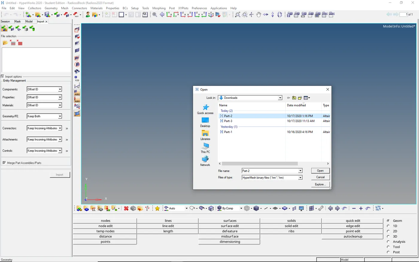
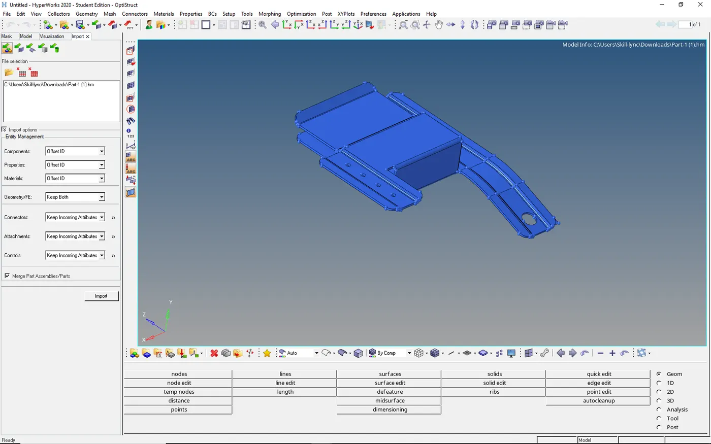
- Geometry cleanup on the model
- As to mesh geometry, the component must posses clean geometry
- To check geometry we need to go visualize and delete those errors
Go to visualize in the menu bar at bottom → keep geometry color mode as mixed
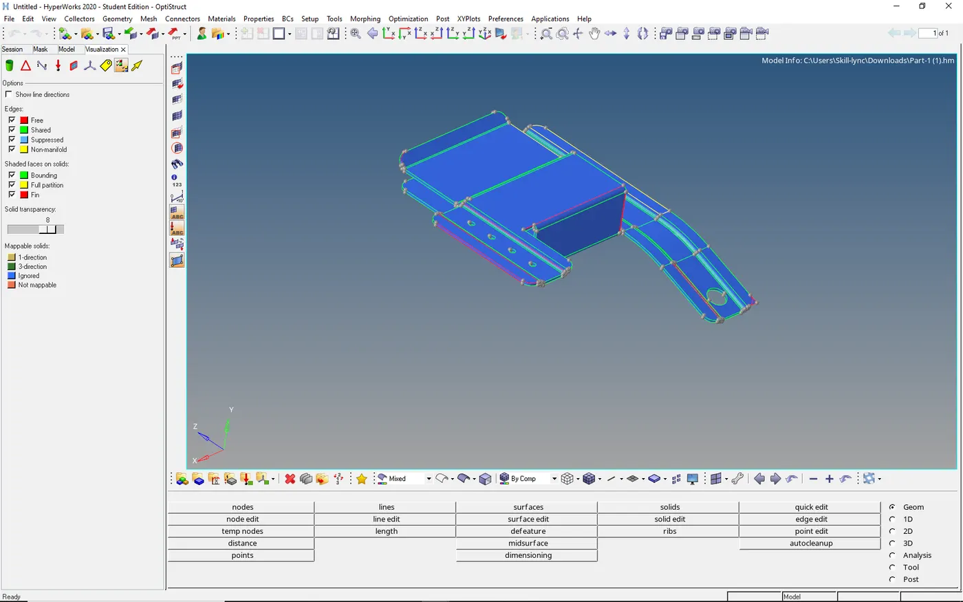
- The geometrical issues are must be removed
- As there are many errors are red color those are edges which are not bounded
- And some of them are yellow they must be deleted because they are duplicate surfaces
Suppress in free edge errors
- They may not be bounded to the neighbor surface we need to bound by toggle edge
Go to quick edit in geometry → select toggle edge → press enter → return
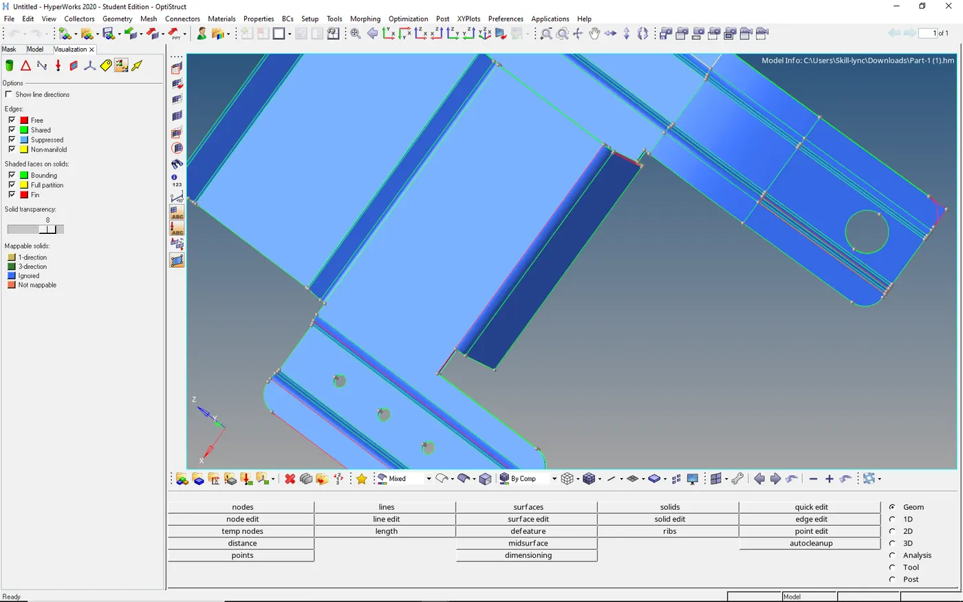
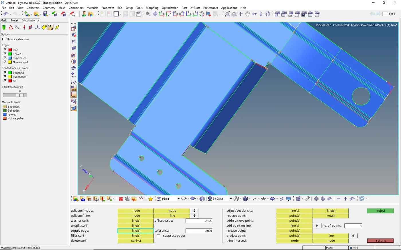
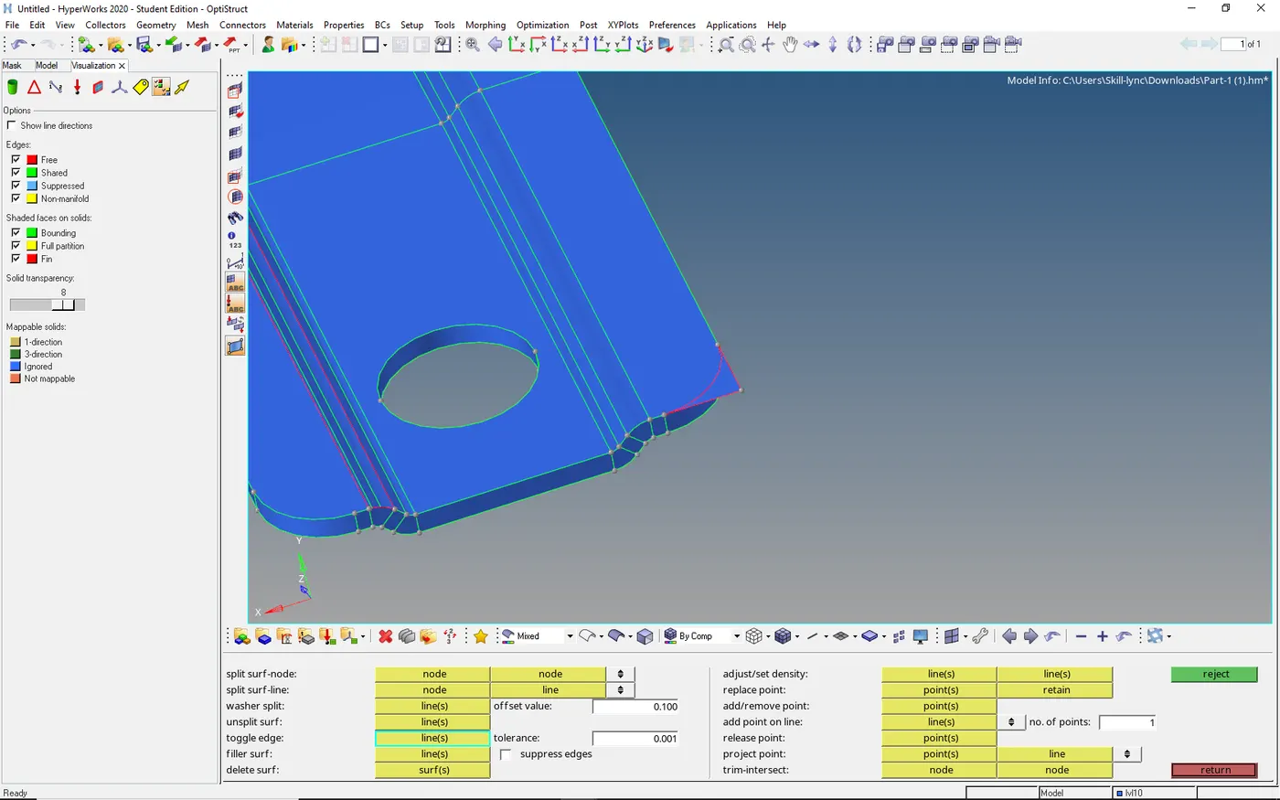
- Here we have extended surface in the component
- To eliminate we need to trim the surface and we need to delete the elongated surface
- And we need to toggle the edge as above
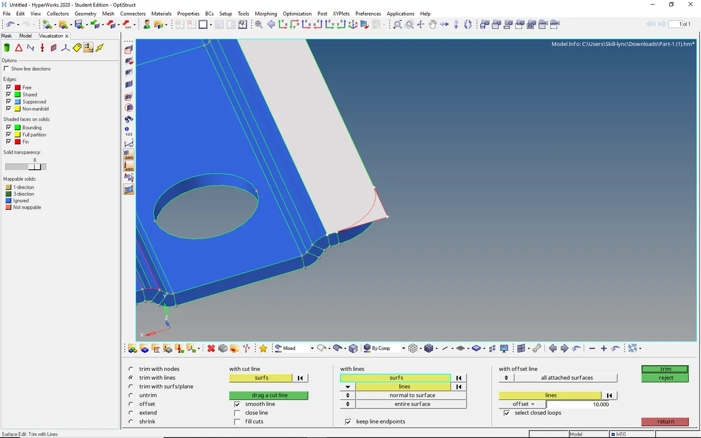
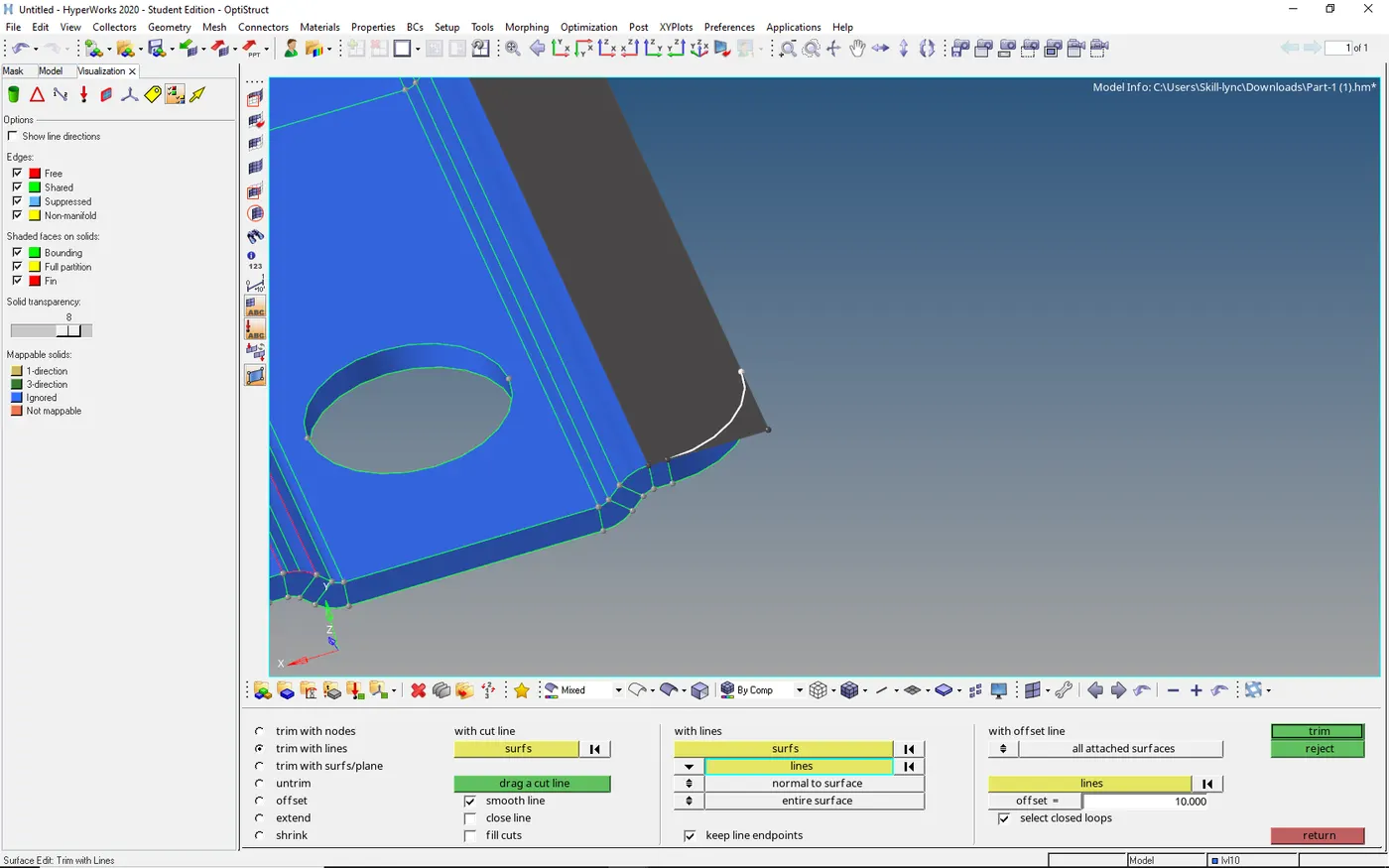
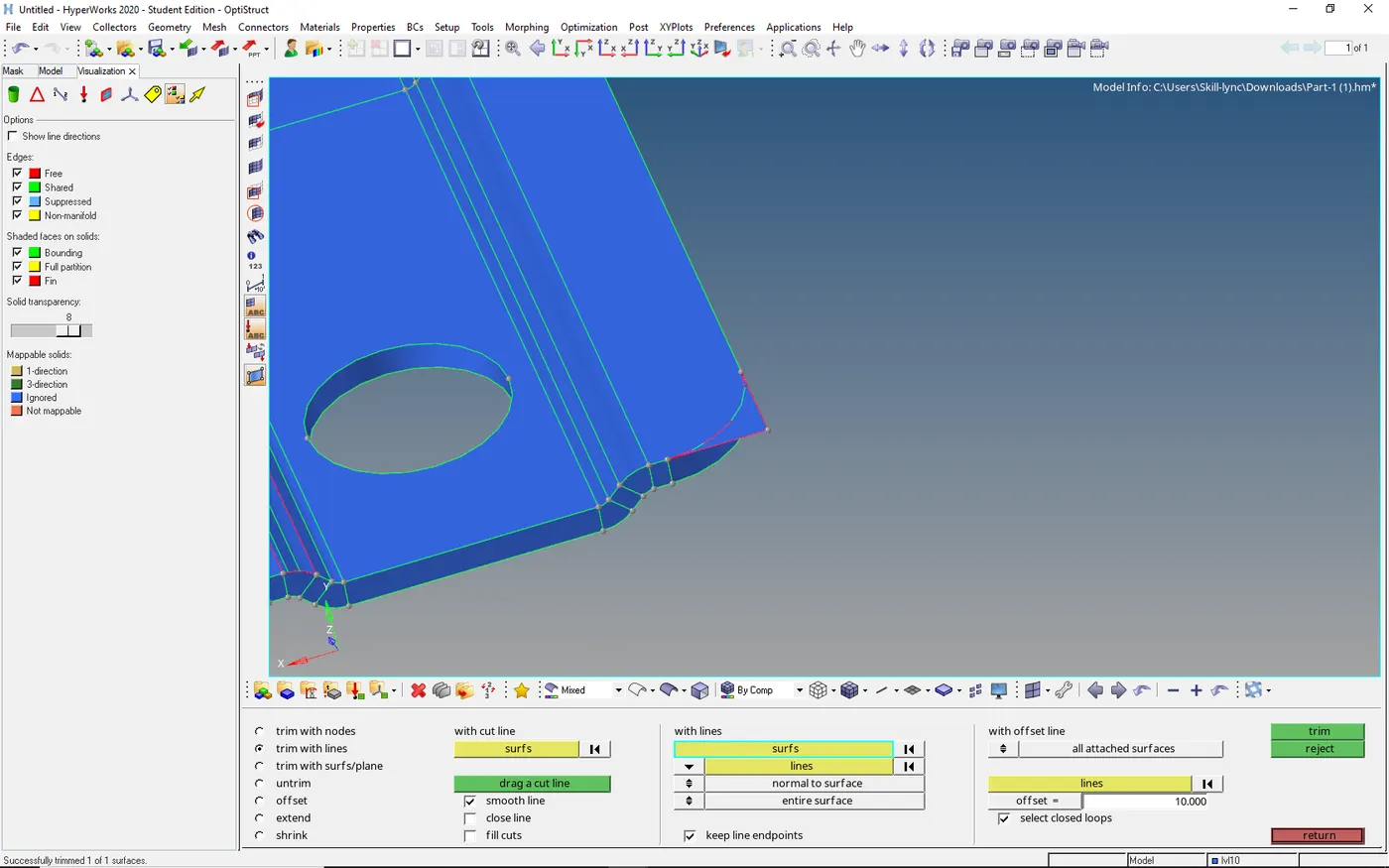
- By universal delete, option delete the extended surface
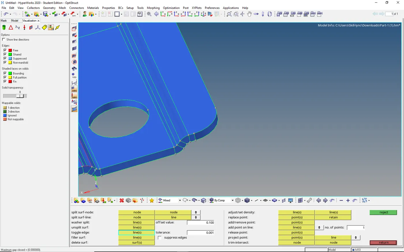
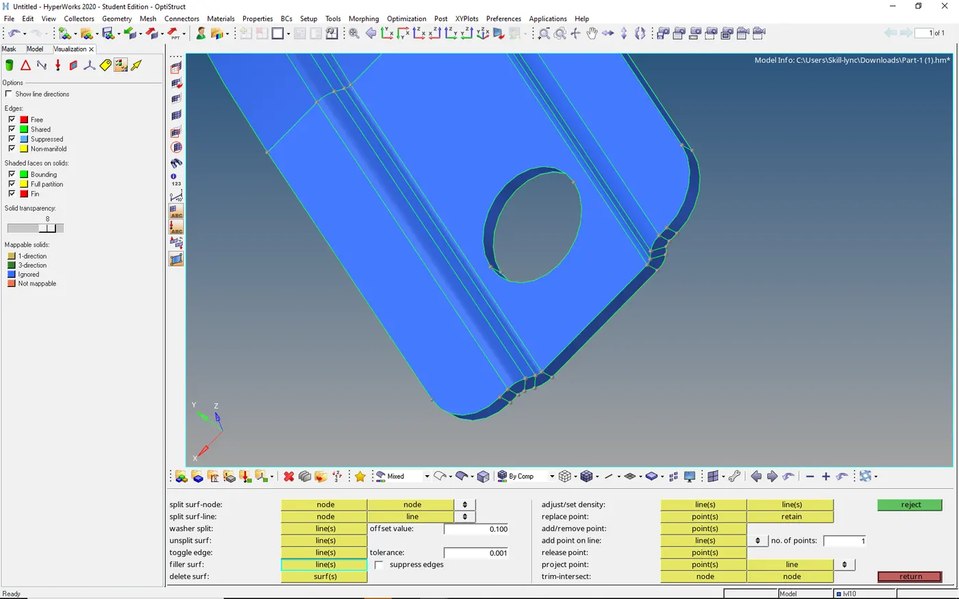
- If the gap between surface is high we need to fill surface
Go to quick edit select → fill surface → enter
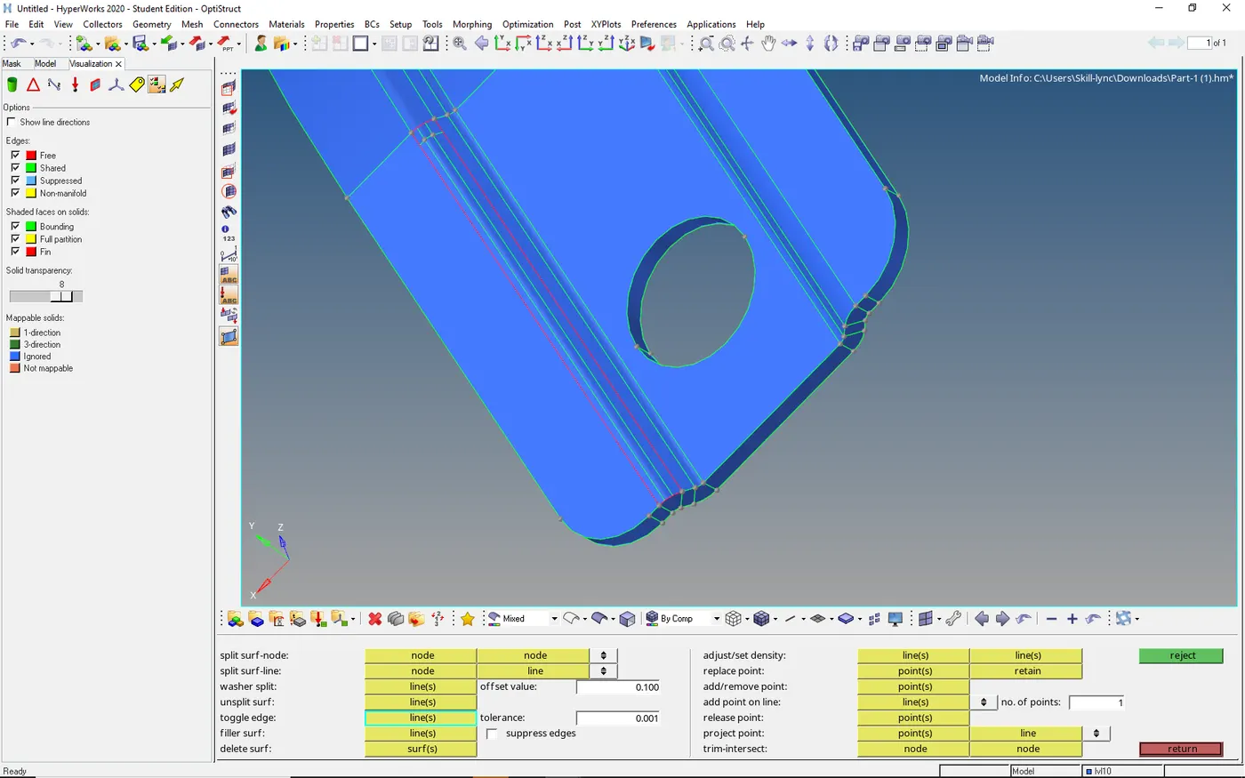
MID SURFACE EXTRACTION:-
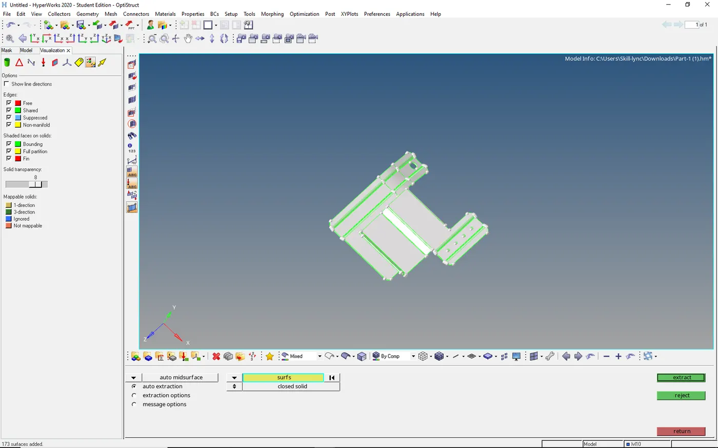
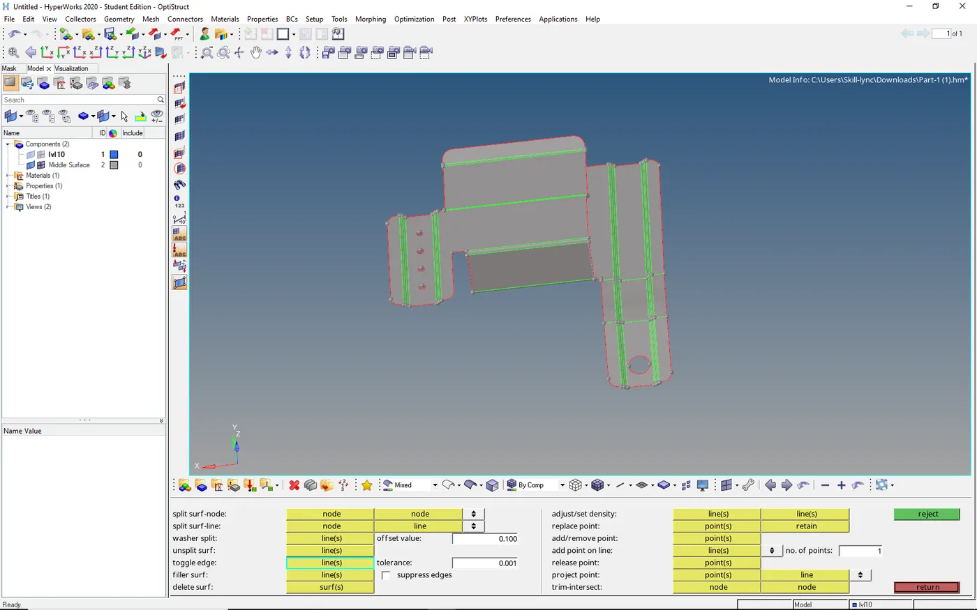
- As of now, we are extracting mid surface automatically
Go to geometry → select mid surface in surface → auto mid surface → select component → press enter
DEFEATURING:-
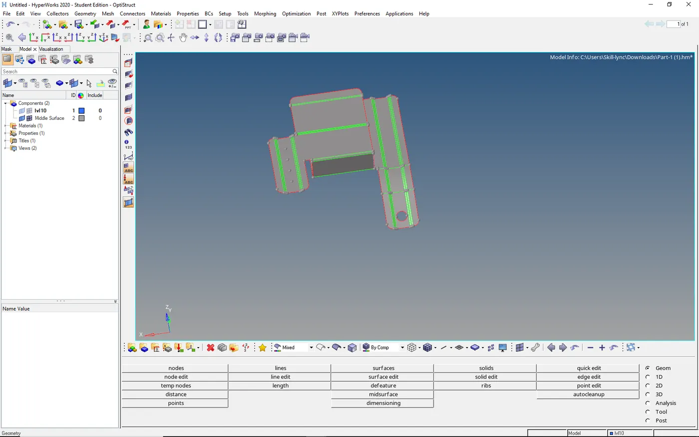
- Some of the fillets or holes are failed due to quality or some of the holes do not change the value without considering them we can achieve better quality.
Go to defeature in geometry → select the pinholes and give minimum diameter/for fillets give minimum dia → select surface → delete


MESHING:-
- To perform mesh we need to give parameters like minimum length and max length etc..
- Then select the surface one by one and mesh it.
For parameters
Go to auto cleanup → select edit criteria → give parameters → apply
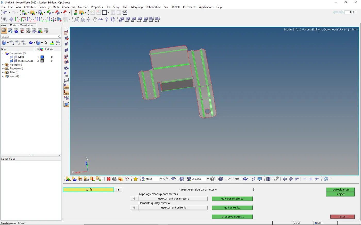
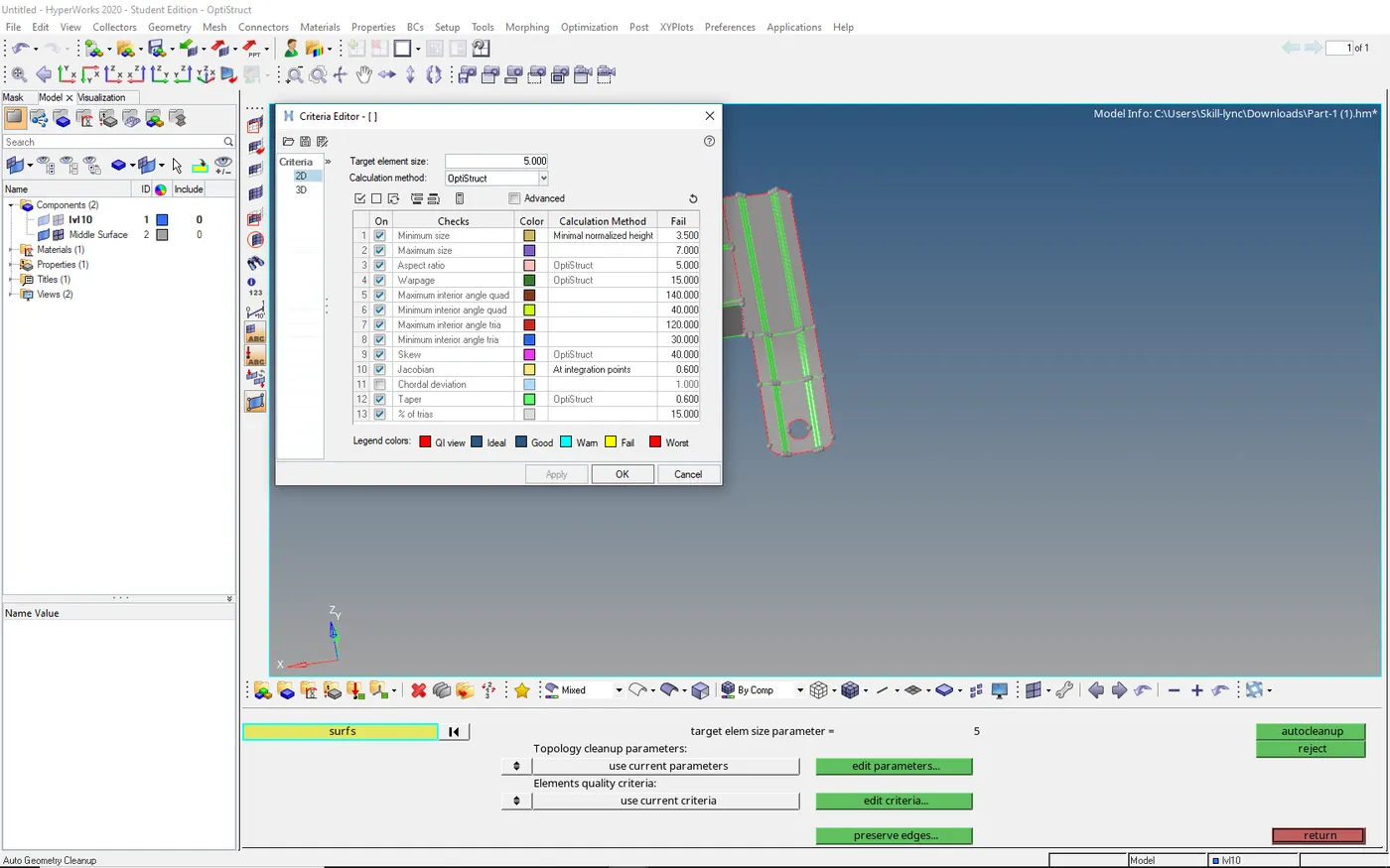
- After that, we need to mesh the part make sure we must satisfy the quality and rules of meshing
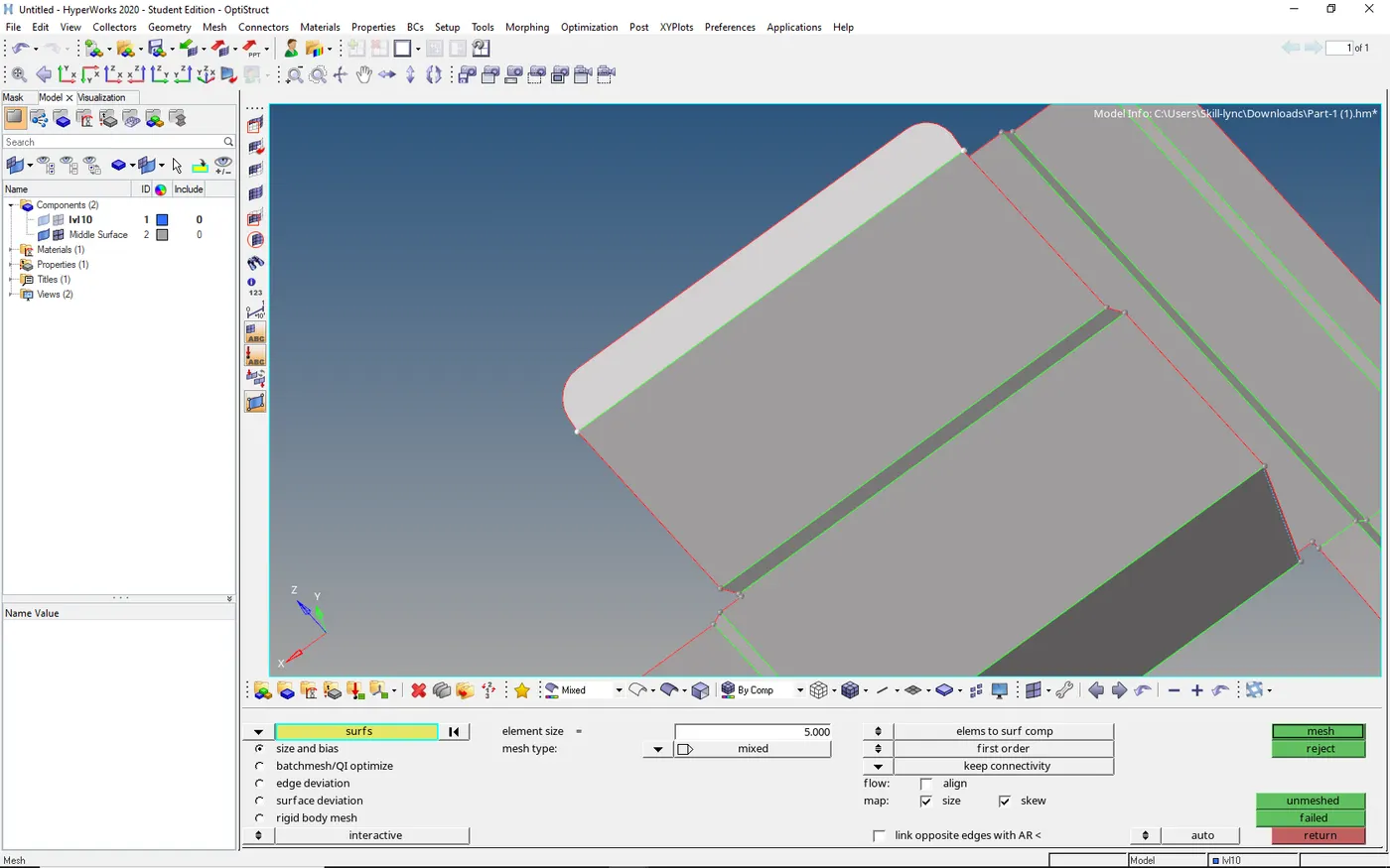
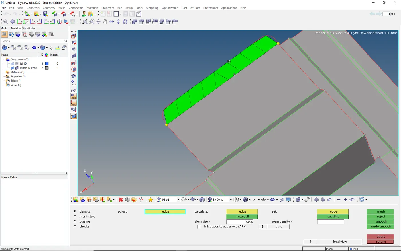
to mesh go to 2d → select auto mesh → select surface → give target element length → select mesh
- After selecting the mesh button mesh will be generated if the mesh is bad then we need to adjust the nodes by right click nodes will increase by left click node will be decreasing.
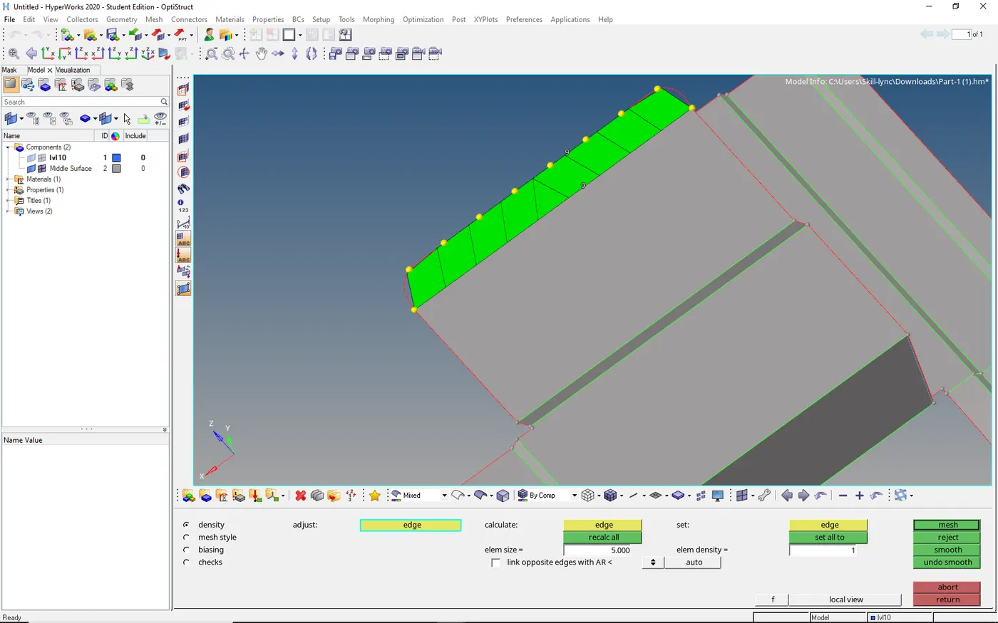
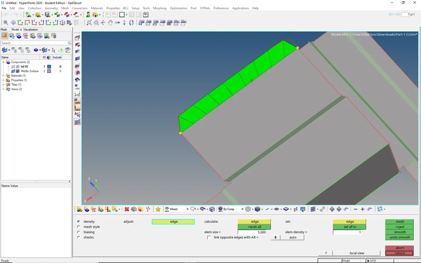
COMMANDS WHICH HELP TO GET GOOD MESH
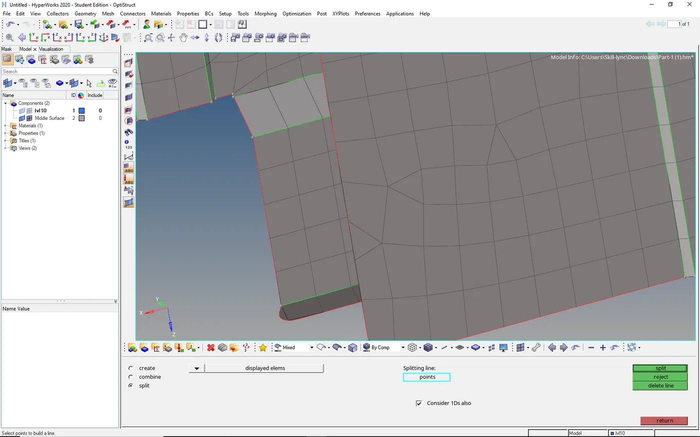
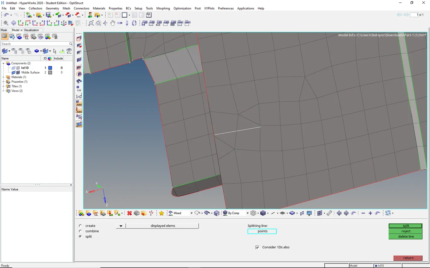
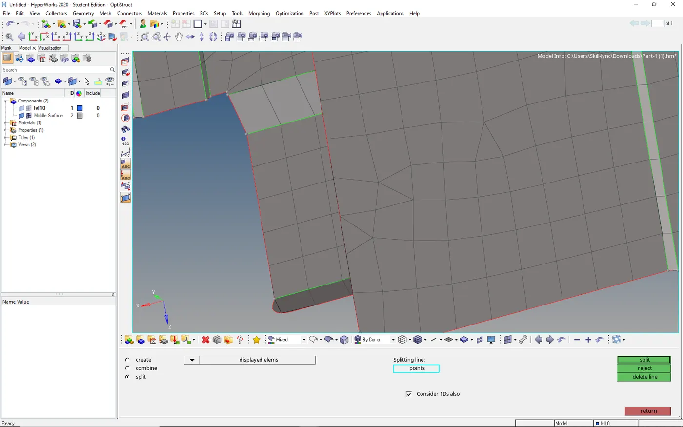
SPLIT
to move tria from the edges
select 2d → select edit element → select split → select the points to split → select split
COMBINE
- As the same steps above just select combine and select two adjacent trias
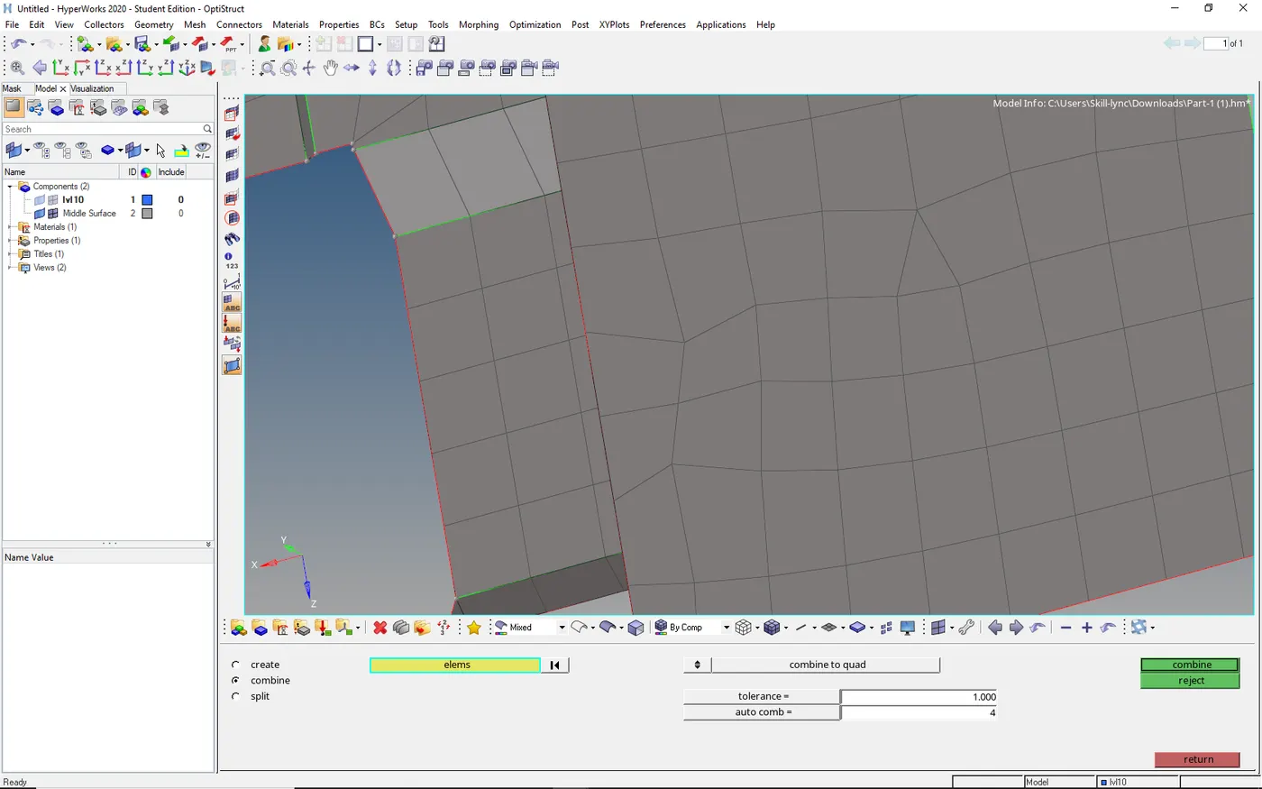
- To get the accurate result we need to remove trias by split and combine we can remove trias
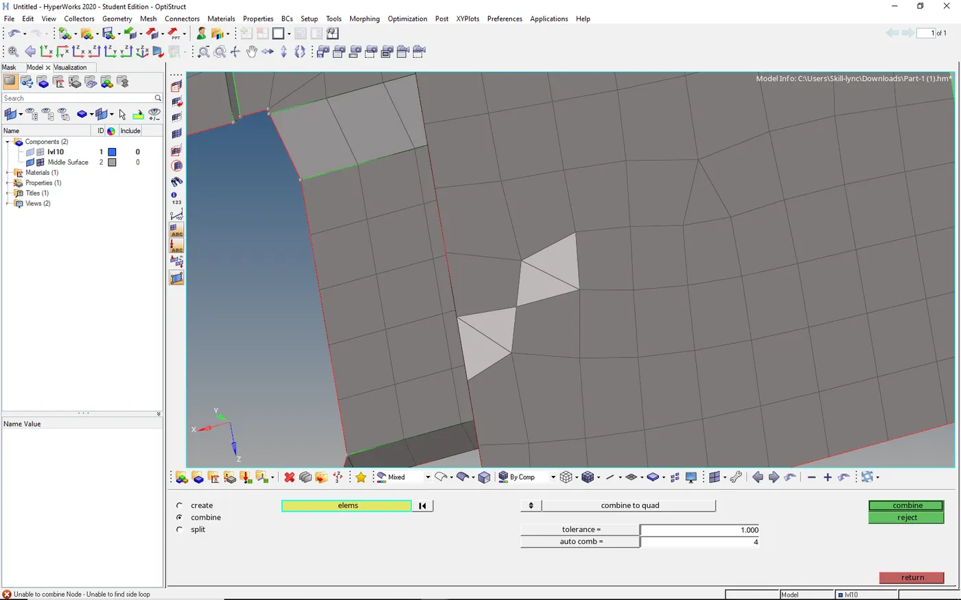
- Make sure that the tria must select in the set of two
QUALITY CHECK:-
- To whether the mesh has satisfied the quality or not we need to check the quality
Go to quality index in 2D → you can see the quality issues
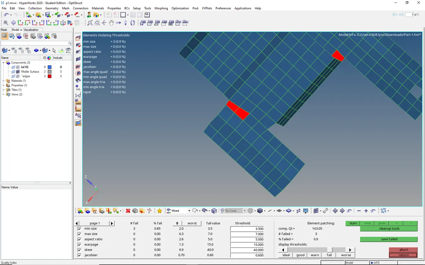
- To reduce quality we had a different tool to reduce the quality
- Select the cleanup tool and use the element optimization or move node to reduce the quality
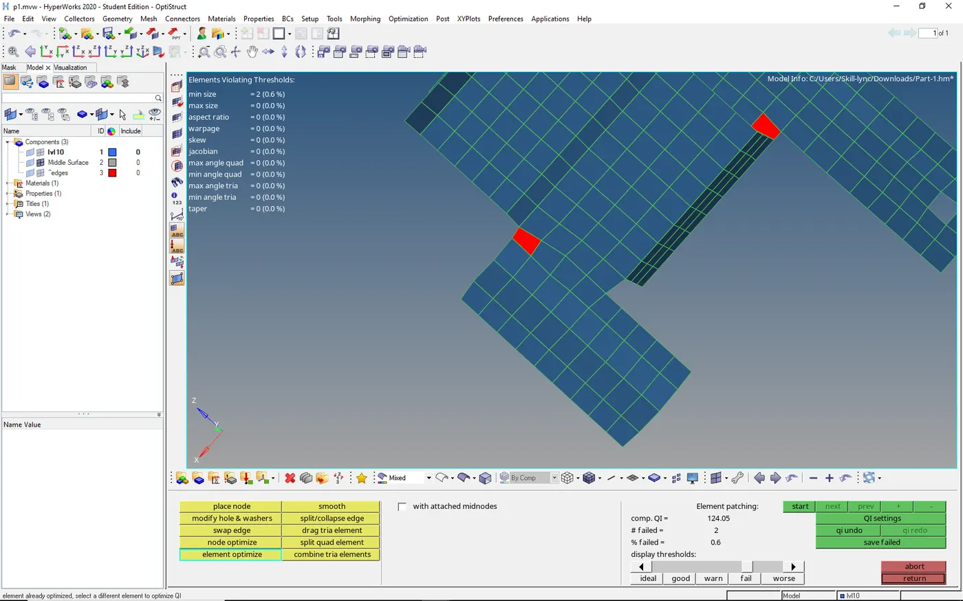
- As the edges are fixed they are not optimized so we need to move the node
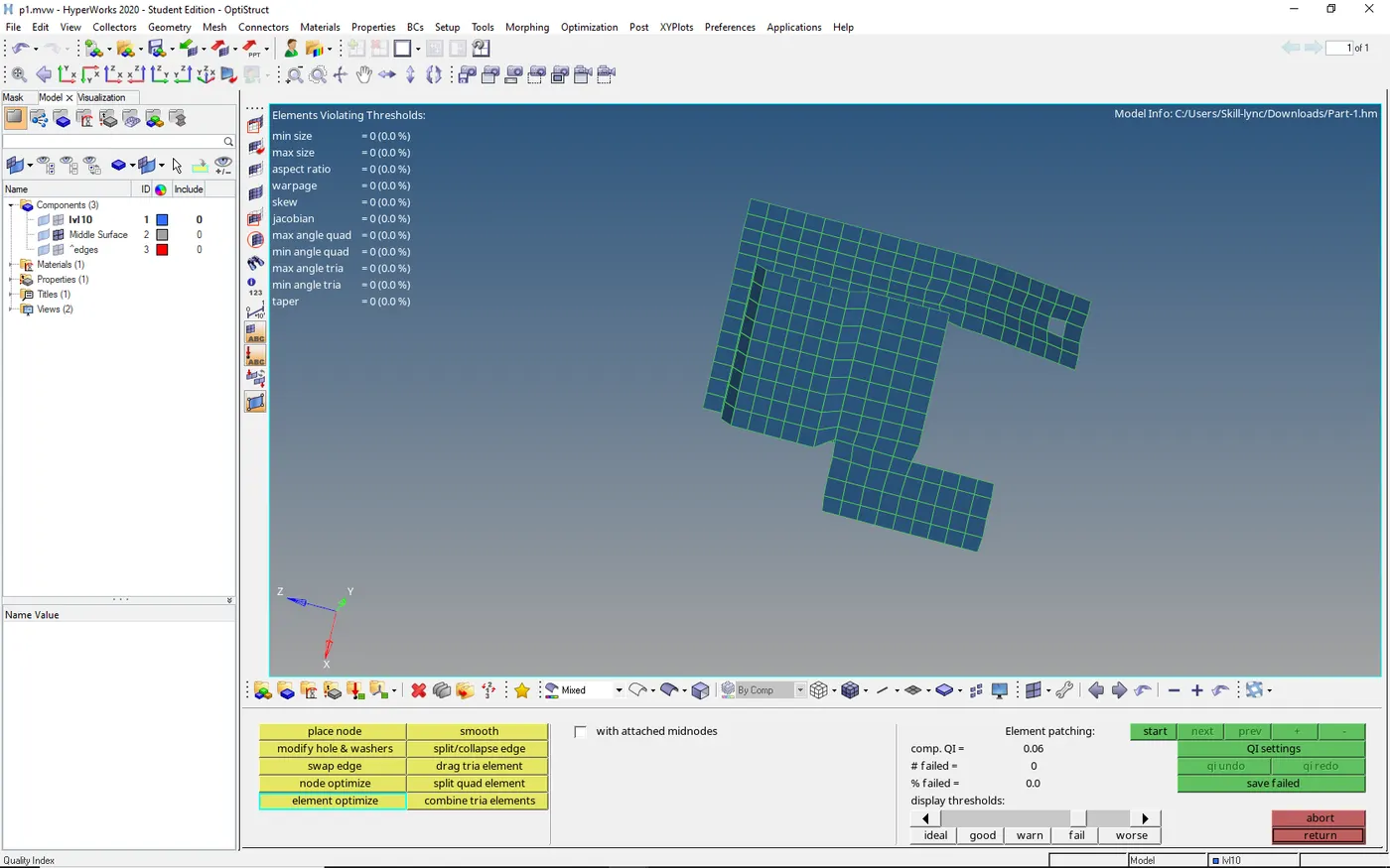
COMPONENTS AFTER MESHING
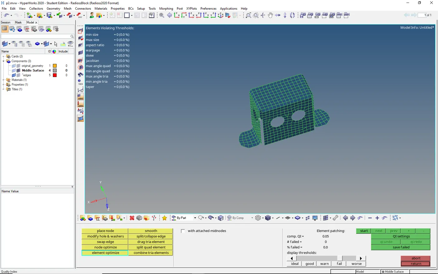
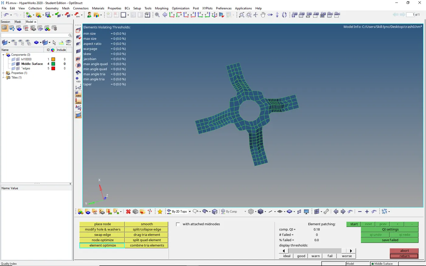
- After meshing assign the thickness to the part and save it
CONCLUSION:-
- Understood the GUI of hyper-mesh
- Performed geometry clean up and the mid surface of sheet metal component
- Performed mesh in hyper mesh
- Assigned thickness to the meshed component