Analysis & Design of RCC shear walls in the model using ETABS
Analysis & Design of RCC shear walls in the model using ETABS
AIM:
- To run the Analysis and Design the RCC Shear Wall
- To extract values of longitudinal steel ratio, boundary element length and shear reinforcing ratio from the design results.
- To provide cross sectional steel arrangement of the shear wall from its base up to terrace, in compliance with provisions of IS 13920 – 2016.
- To provide elevation drawings of the reinforcement details of the shear wall from base up to terrace.
INTRODUCTION:
- Shear wall is a structural member in a reinforced concrete framed structure to resist lateral forces such as wind forces and seismic forces.
- Shear walls are generally used in high-rise buildings subject to lateral wind and seismic forces. In reinforced concrete framed structures the effects of wind forces increase in significance as the structure increases in height. Codes of practice impose limits on horizontal movement or sway.
PROCEDURE:
- Open the ETABS software.
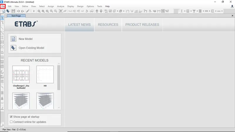
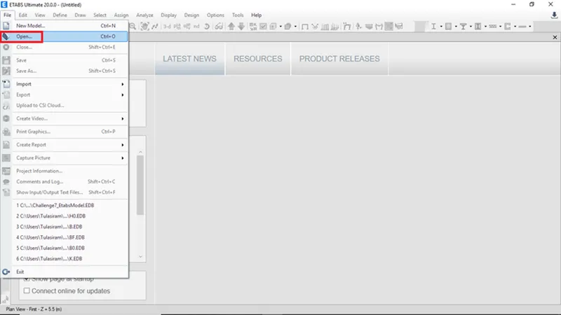
- Then go to File menu then click on open to open the provided ETABS file.
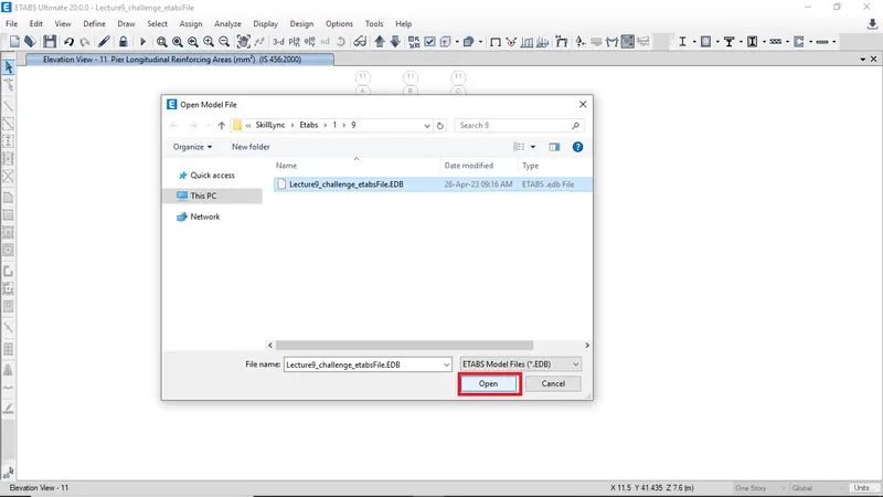
- Browse the ETABS file then click open
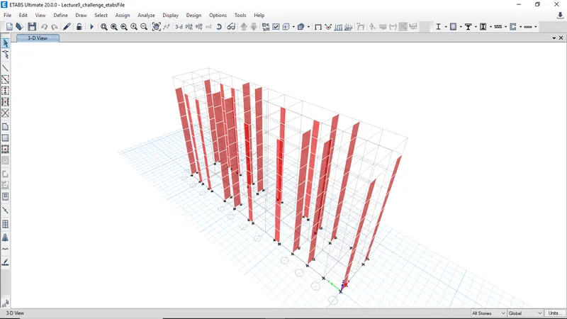
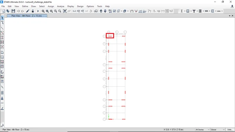
- To design the shear wall at grid A11 switch view to elevation view
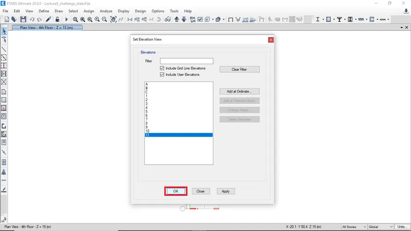
- Set elevation view to grid 11 then click ok
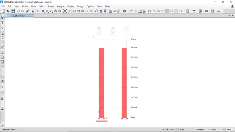
- The shear wall in left side need to be analysed and designed
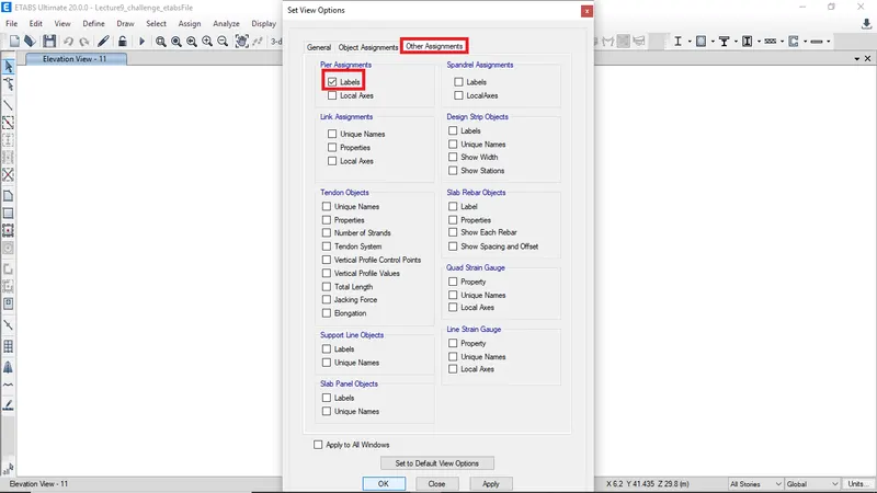
- To view the assigned pier labels to shear wall go to see view options, in other assignments check labels and then click ok
- The assigned pier labels will be visible
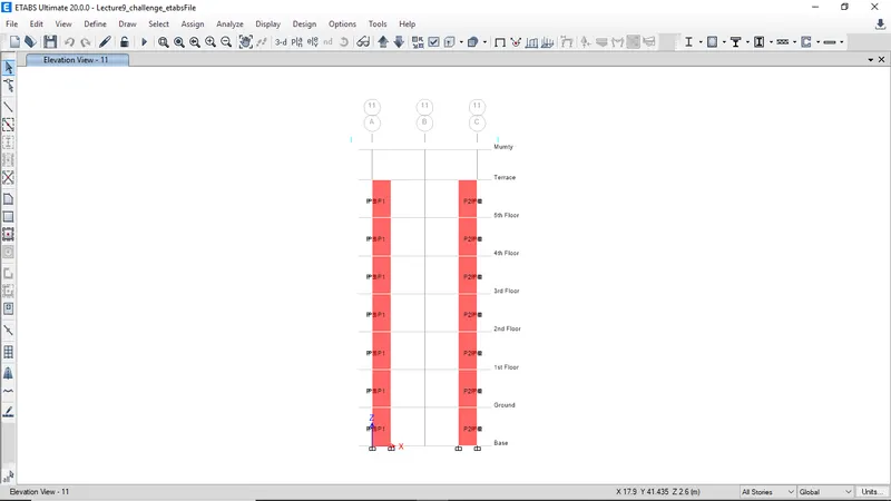
- Click on run to run analysis
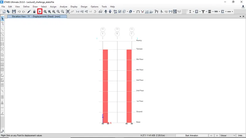
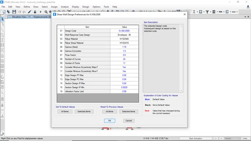
- View shear wall preferences
- After successful completion of analysis then click on shear wall design.
- In the shear wall design click on start design/check.
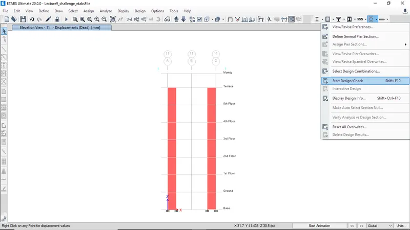
- After design check click on display design info to view the reinforcement details
- Right click on respective shear wall to view the shear wall design details
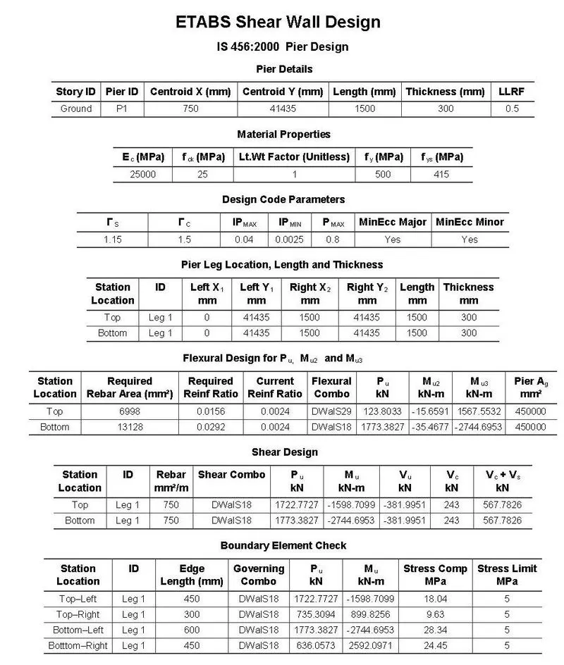
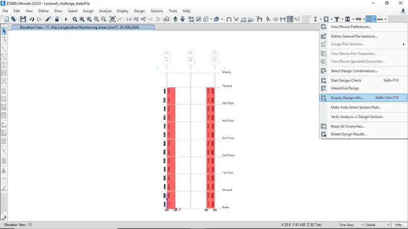
- The storey data can be viewed in the below provided image
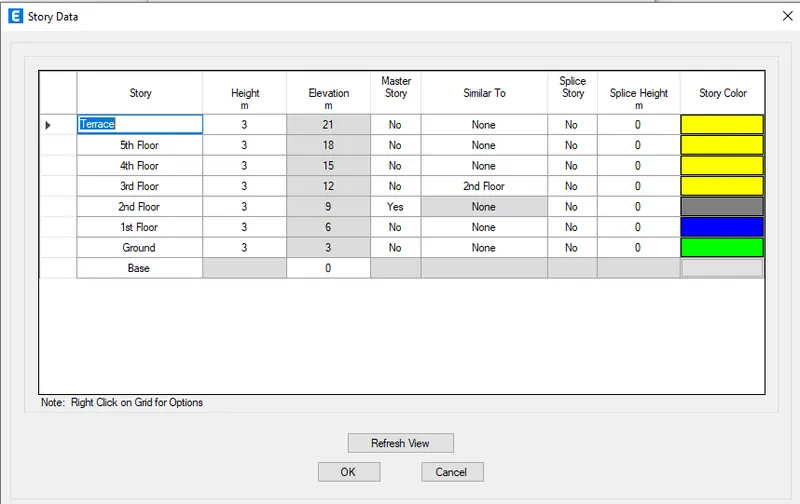
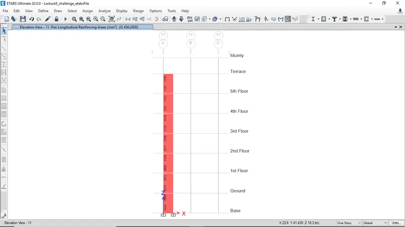
- Select pier longitudinal reinforcement to view the longitudinal reinforcement details
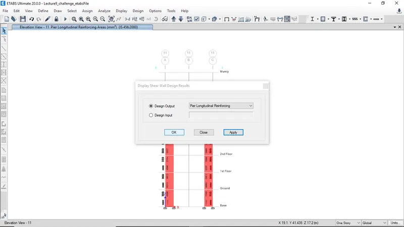
- The longitudinal reinforcement area details now visible
- Goto shear wall design and click display design info
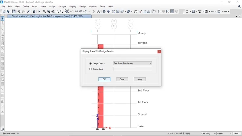
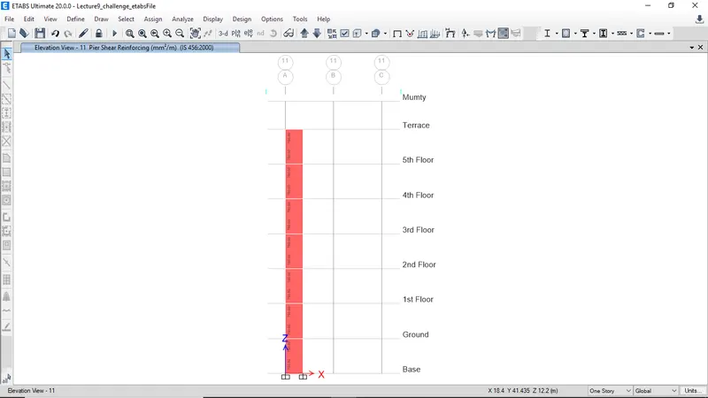
- Select the shear reinforcement to view the horizontal reinforcement details
- The horizontal reinforcement area details now visible
- Goto shear wall design and click display design info
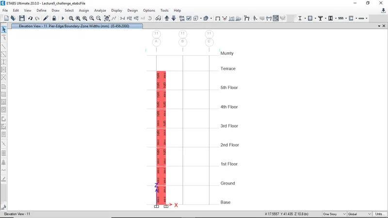
- Select the Pier edge/ Boundry Zone widths to view the pier length details
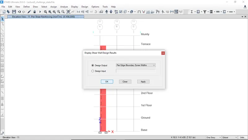
- The boundry element lengths are visible
SHEAR WALL DETAILING USING ETABS DESIGN RESULTS AS PER IS 13920-2016
- Classification of wall as per the code IS 13920-2016 clause 10.1.4
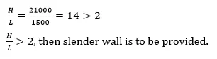
Hence it is a slender wall - The net minimum reinforcement required as per code IS 13920-2016 Table-1
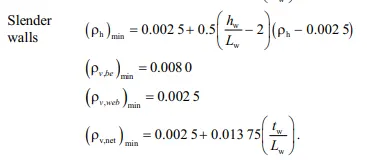
-
Min longitudinal reinforcement required = `0.0025+0.01375 *300/1500 =0.00525`
Min Ast = 300 x 1500 x 0.00525 = 2362.5 mm2Since Etab designed Ast is greater than min required Ast. Hence it is safe.
And as per the clause 10.4.2.1 the vertical reinforcement shall not be less than 0.8% and more than 6%.
Min vertical reinforcement for left boundary element is 600 x 300 x 0.8% = 1440 mm2
Min vertical reinforcement for right boundary element is 450 x 300 x 0.8% = 1080 mm2
Hence safe.
Max dia of bar to be provide as per IS 13920 2016 clause 10.1.8
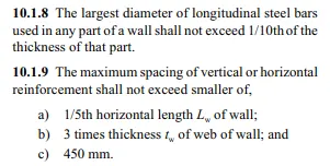
Largest diameter = 300/10 = 30 mm
Longitudinal reinforcement for shear wall from base floor to first floor
We can provide maximum 25 mm dia bar as per availability.
Provide 25 mm dia of bar
Asv= 490.87 mm2
Total number of bars required = `13128/490.87 =26.7`
Therefore provide 28 numbers of 25 mm dia of bar
Longitudinal reinforcement for shear wall from first floor to terrace floor
Provide 16 mm dia of bar
Asv= 201.06 mm2
Total number of bars required =`4896/201.06 =24.35`
Therefore provide 26 numbers of 16 mm dia of bar
Horizontal reinforcement for shear wall
- Min horizontal reinforcement required as per Etabs design is 750 mm2 / m to be provided through out.
Check for horizontal reinforcing as per IS 13920 - 2016
Min horizontal reinforcement = `0.0025 + 0.5 * (21000/1500-2)(750/(300*1000)-0.0025)`
Assuming 2 legged stirrups of 10 mm dia
Min horizontal reinforcement = 0.0025
The provided reinforcement design is as same as min shear reinforcement.
Hence it is satisfied.
Ash = 157.07 mm2
No of bars per meter length =`750/157.07= 4.77`
Max spacing = `1000/4.77` = 209 mm
Therefore, provide 2 legged stirrups of 10 mm dia at 200 mm spacing in web element
Also, for boundary element need to provide confining reinforcement as per IS 13920-2016 clause 10.4.4
Provide additional stirrups of 8 mm dia in between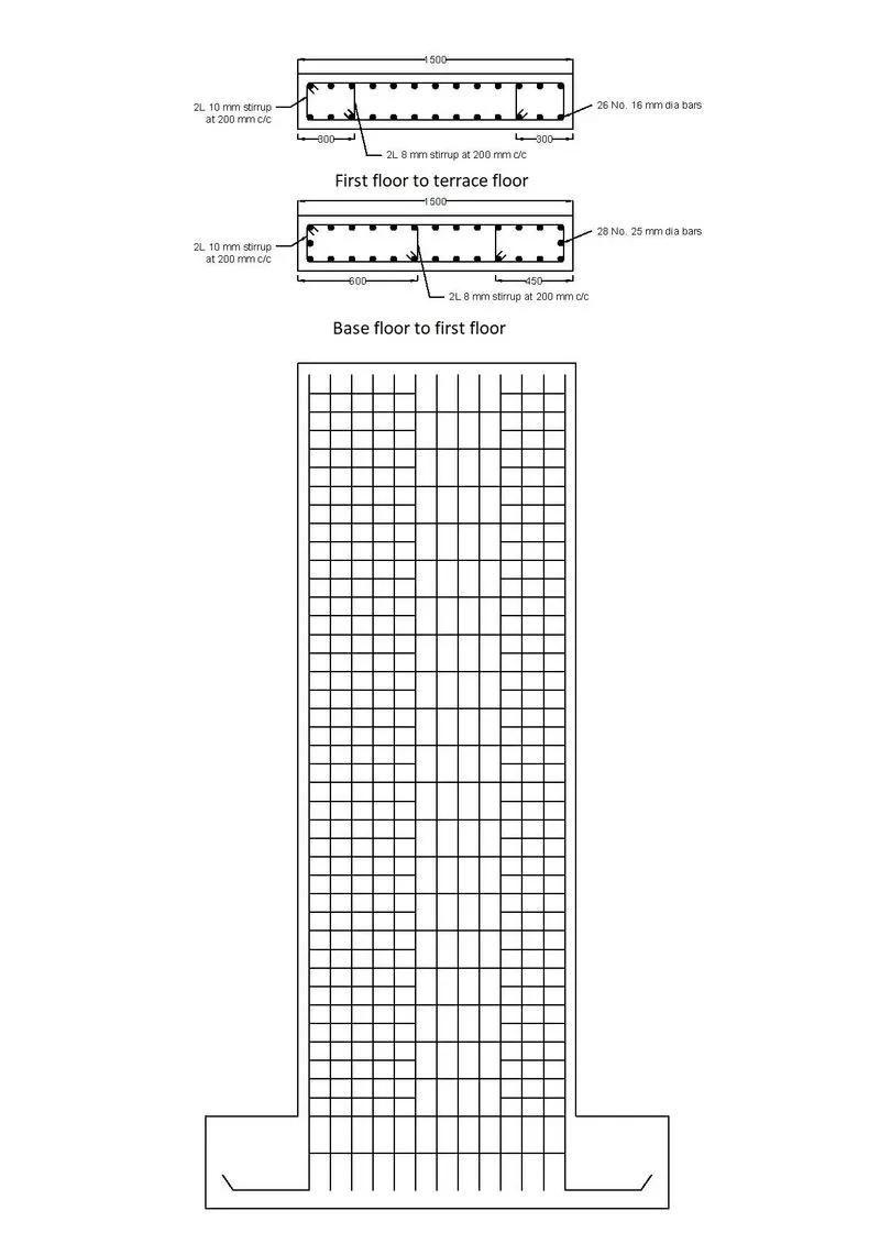
Result:
- Analysis was performed and RCC Shear Wall was designed.
- Provided cross sectional steel arrangement of the shear wall from its base up to terrace, in accordance with provisions of IS 13920 – 2016
- Extracted values of Longitudinal reinforcement, Boundary Element Length and horizontal Reinforcement from Design results.
- Designed the RCC shear wall using the design results from ETABS file.