Advanced Sheet Metal Design Using NX Cad Challenge_7_ Metal bracket-II
Bracket – II
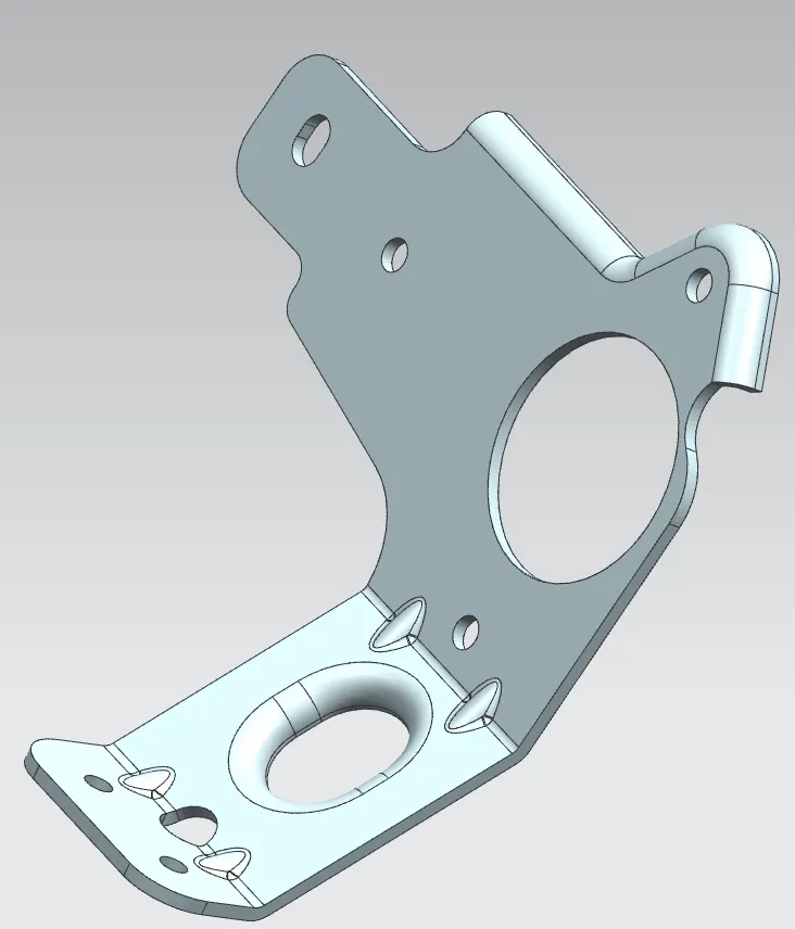
Objective: Design a 3D model bracket using Siemens-NX sheet metal.
Introduction:
Sheet metal design is essential in many areas, especially in aerospace, machinery, and automobile industry. The sheet metal designing process become essential as the industry developed and adopt the advanced manufacturing process. The sheet metal designing process helps to speed up the manufacturing process and reduce waste and cost drastically There are many software to support these designing processes, each having its unique features and commands. Siemens – NX is one of the CAD/CAM/CAE software that many industries prefer, especially works related to sheet metal and thin surfaces. Here we will be using the software to design a bracket using the NX sheet metal feature and create a blank workpiece daring from the model.
Design Methodology:
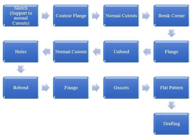
Description:
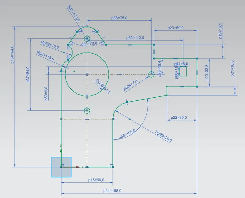
A sketch is created on the ‘Y-Z’ plane. The sketch will later act as a support to the normal cutout feature.
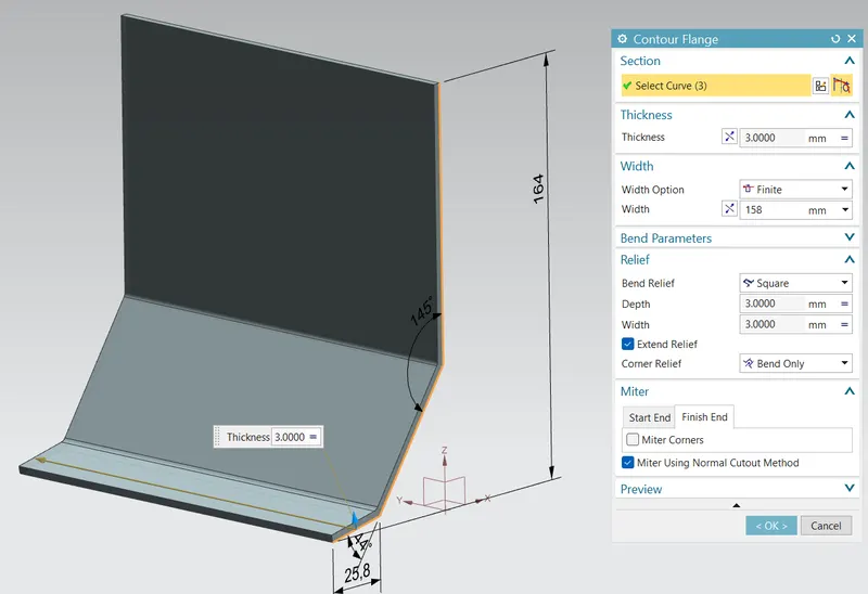
The ‘Contour Flange’ feature is used to make a model corresponding to a new sketch (X – Z plane).
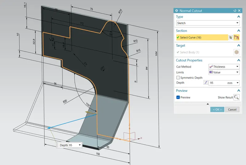
The sketch made earlier is used as a support to the command ‘Normal Cutout’ and the command is completed.
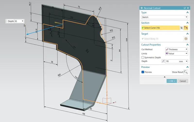
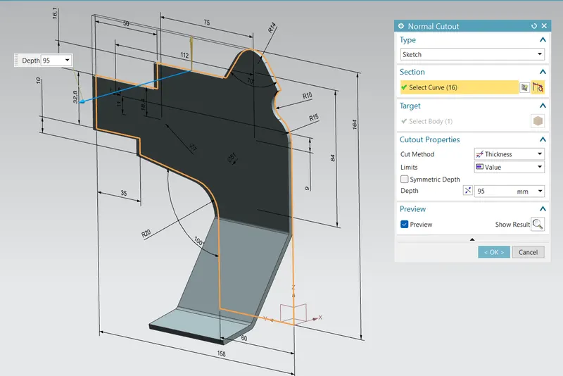
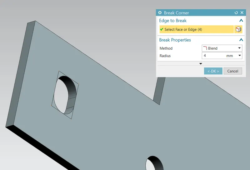
The command ‘Break Corner’ is used to smoothen the sharp corners.
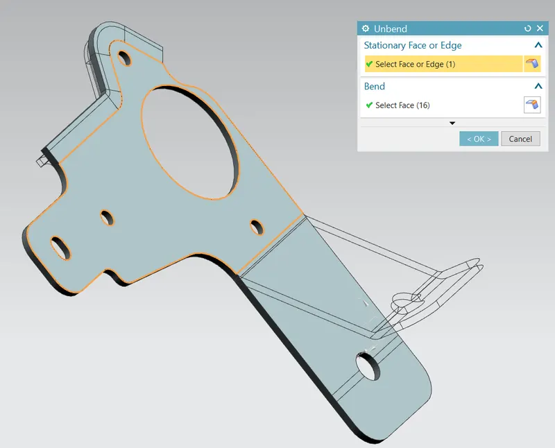
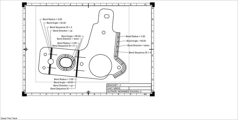
The shape then flattened using the ‘Unbend’ command.
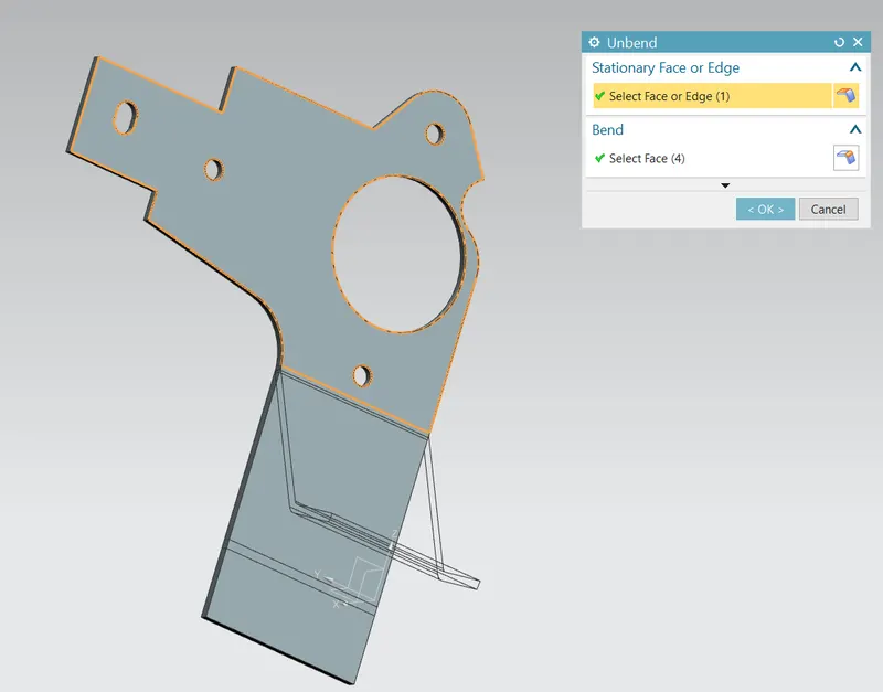
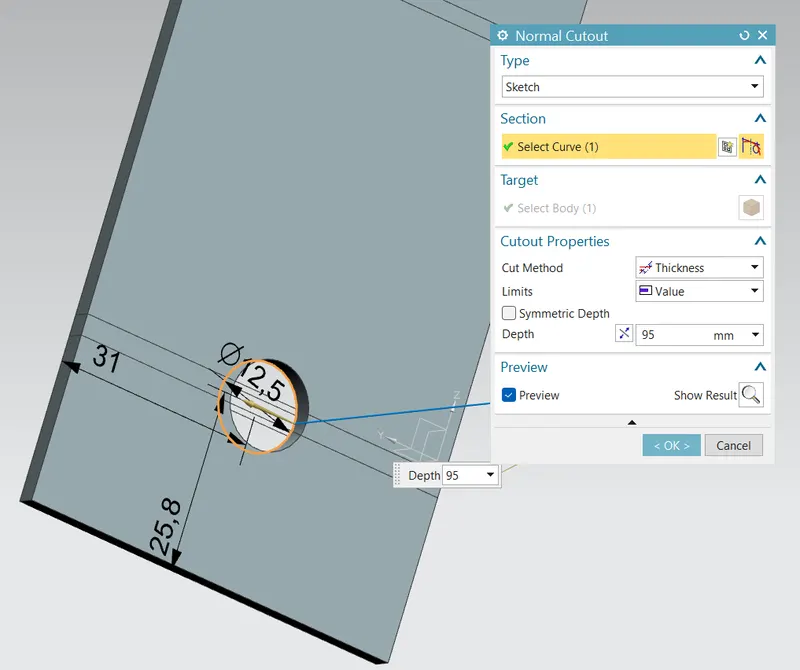
The command ‘Normal Cutout’ is used again to cut out at the center of a bend.
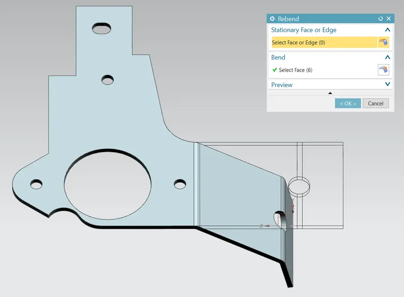
The structure is folded back, for this the command ‘Rebend’ is used.
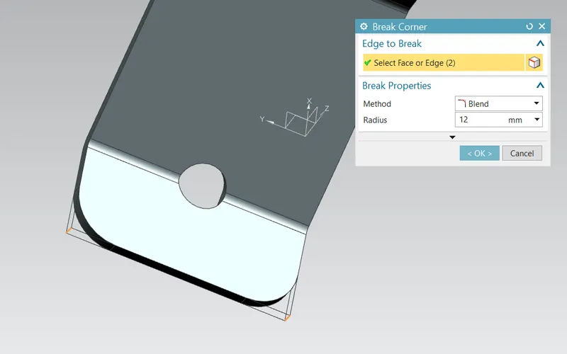
The remaining sharp corners are smoothened using ‘Break Corner’.
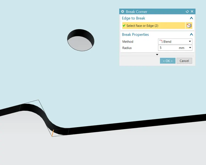
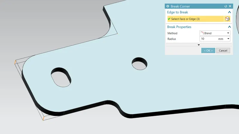
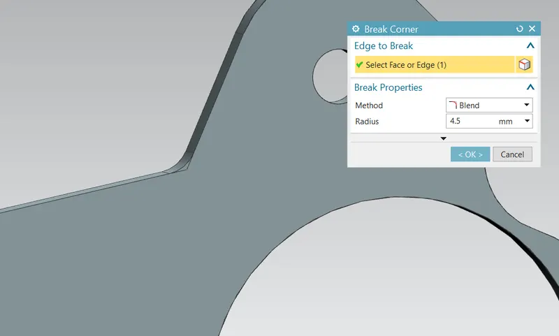
A flange is created using the command ‘Advance Flange’ to create a flange around bend edges.
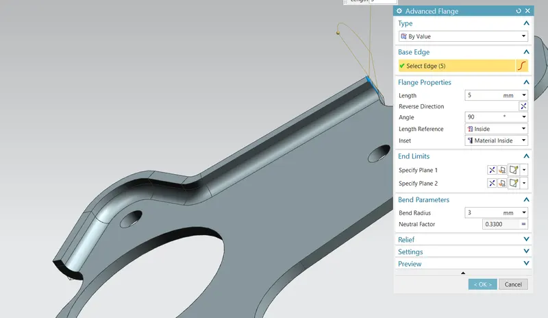
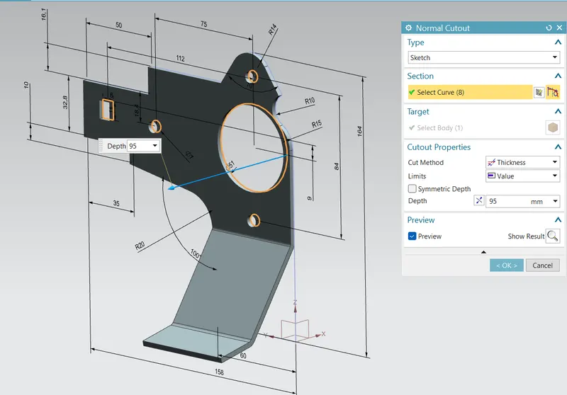
The model is flattened again using the ‘Unbend’ command and a couple of holes and a normal extrude cut is made using the command ‘Hole’, and ‘Normal Cutout’ respectively
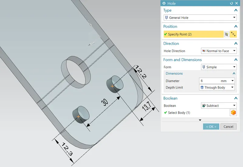
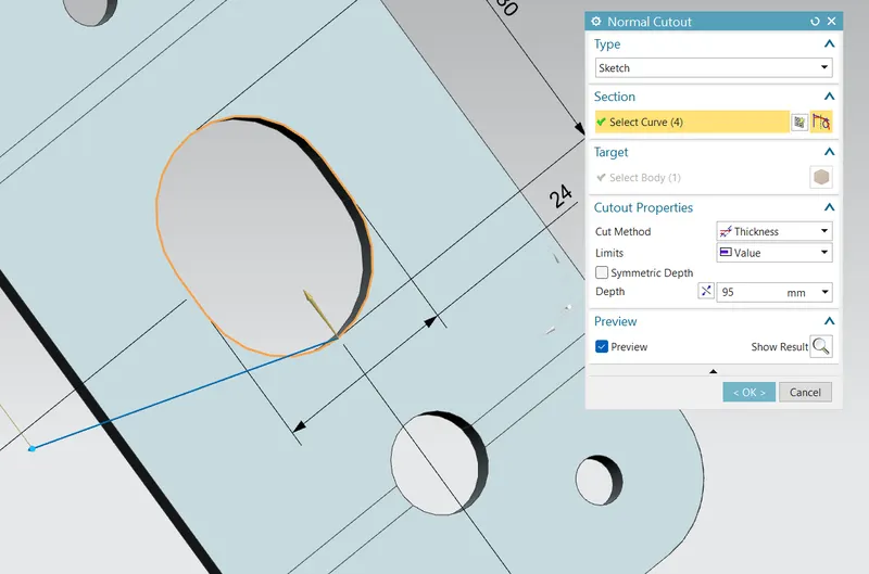
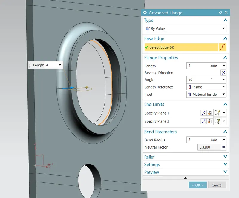
A flange is introduced over one of the cutout edges using the command ‘Advance flange’, and the model is folded back again using the command ‘Rebend’.
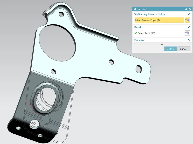
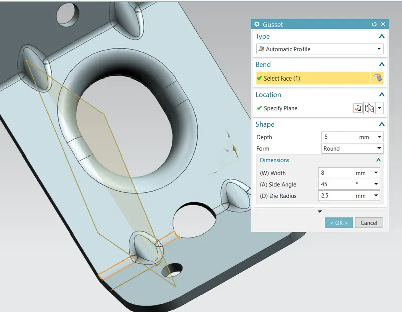
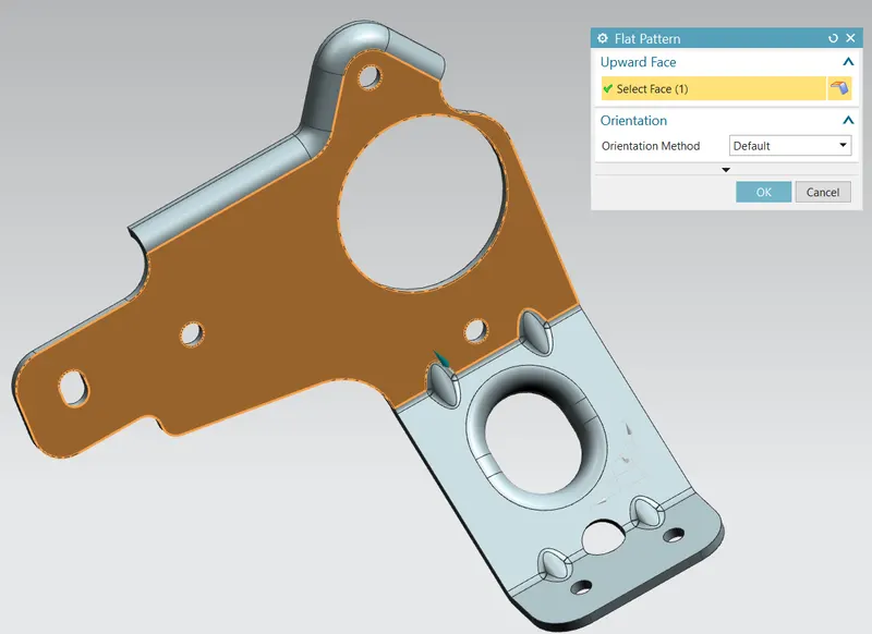
Multiple gussets are made on the structure to increase the strength of the model. The 'Gusset' command is used to introduce gussets. Finally, the command 'Flat Pattern' is used to make a flat pattern for drafting uses.
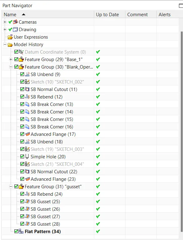
Feature Tree
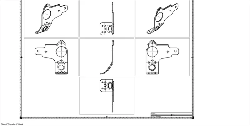
Standard Views
Front View
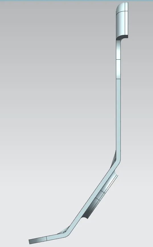
Left Side View
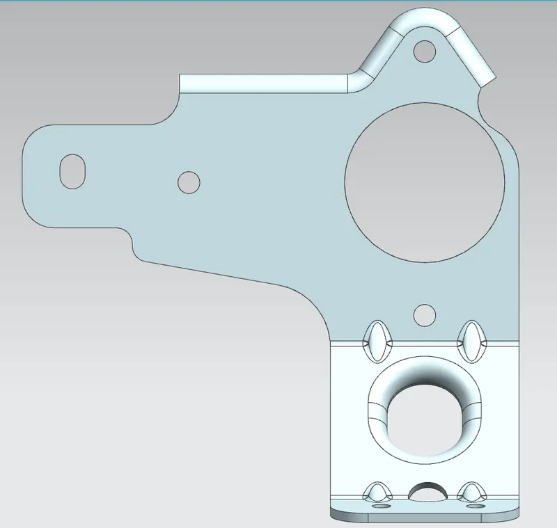
Top View
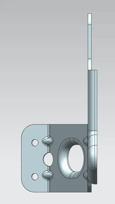
Right Side View
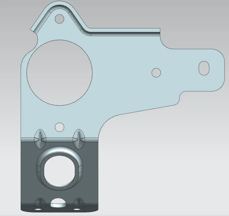
Isometric View
Drawings (Draft)
Conclusion
The model is made in Siemens - NX sheet metals and adavance features are introduced while modeling. The blank model is drafted on a sheet for manufacturing purposes.