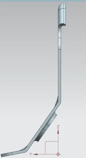
Advanced Sheet Metal Design Using NX Cad Challenge_7_ Metal bracket-II
TITLE:
Design of sheet metal bracket 2 using NX-CAD
OBJECTIVE:
To design the sheet metal bracket 2using NX-CAD and also draft the flattened sheet metal design.
INTRODUCTION:
Brackets are connecting devices used to join two objects. In architecture, they may be made of wood or stone and used to join walls with features like parapets or eaves. In engineering, however, they are often made of sheet metal and used to support objects like shelving, countertops, flooring, sections of furniture, and mounted televisions.
Although there are many types of brackets, they are most commonly L-shaped, with the vertical section of the bracket attached to a wall (or another large upright structure) and the horizontal section attached to a smaller object being fitted to the wall, such as a shelf.
Brackets often have holes in them, either threaded or unthreaded, so that screws or other fasteners can be fed through them, but this is not a defining feature of the bracket.
Most brackets are functional, with their purpose being to connect and support objects. However, brackets can also be decorative: since brackets are often visible (such as on shelves mounted above eye level) they may have cosmetic features and flourishes, from intricately machined decorative features to gold plating.
Flowchart:
- Contour flange
- Body and internal cutout
- Unbend
- Create hole and cutouts
- Rebend
- Break corner
- Advanced flange
- Gusset
PROCEDURE:
1. Create Contour flange
- First of all open the NX-CAD file and create new sheet metal file with proper naming.
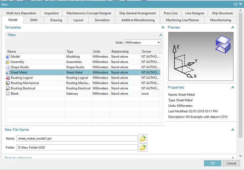
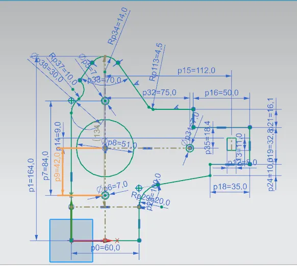
- Next open the sketch option from direct sketch tab and select the XZ plane, specify the vertical vector as X vector and specify the part origin.
- Draw the front view of sketch with dimensions shown in reference diagram at origin (0,0,0).
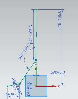
- Next open the sketch option from direct sketch tab and select the YZ plane, specify the vertical vector as Y vector and specify the part origin.
- Draw the side view of sketch with dimensions shown in reference diagram at origin (0,0,0).
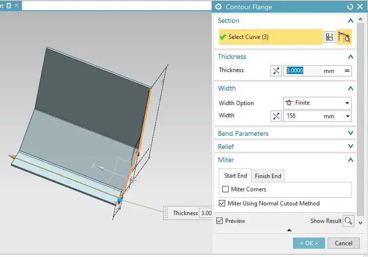
- Modulate the skecth into contour flange by selecting the contour flange option from bend tab and choose the lines, enter the thickness value as 3 mm and width as 158 mm.
2. Create normal Cutout
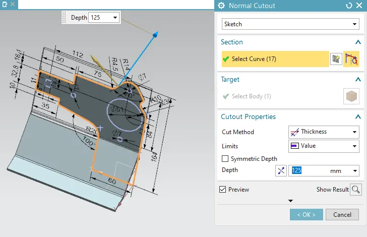
- Refer the front view sketch for cutout curve.
- Cutout the outline sketch by choosing the normal cutout command on feature tab and enter the value as 35 mm depth and cut method as thickness.
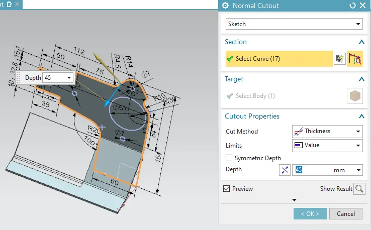
- For bottom part follow the same procedure and increase the depth in opposite direction.
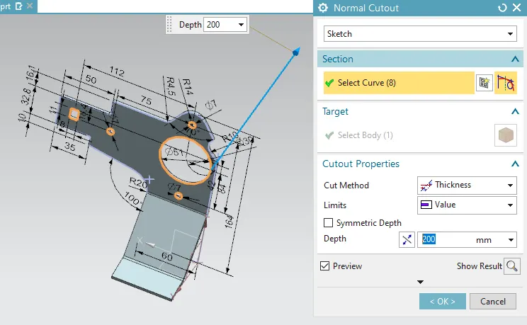
- The front view sketch has some internal holes and cavities use normal cutout and select those specific internal curves only.
3. Unbend the 3D sheet to flat sheet
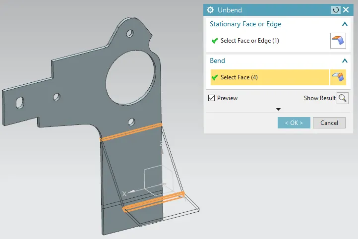
- Unbend the 3D sheet metal design to flattened sheet metal, by using unbend command from form tab and select the edges and adjacent faces.
4. Create holes and cutouts
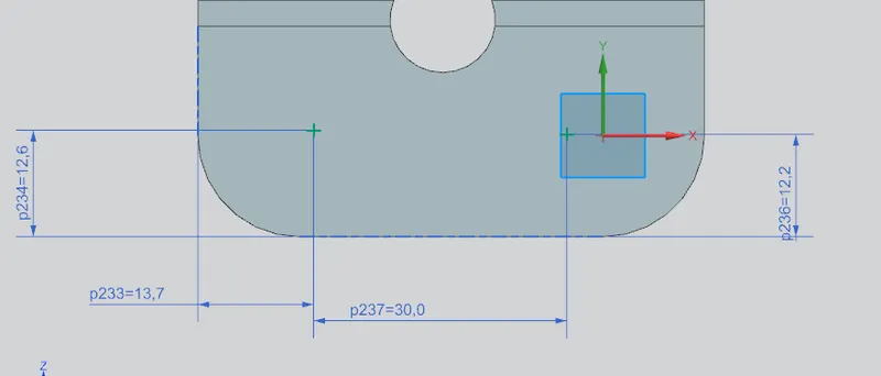
- Create holes at ends of the sheet by using direct sketch tab>sketch>points with dimensions specified in given diagram.
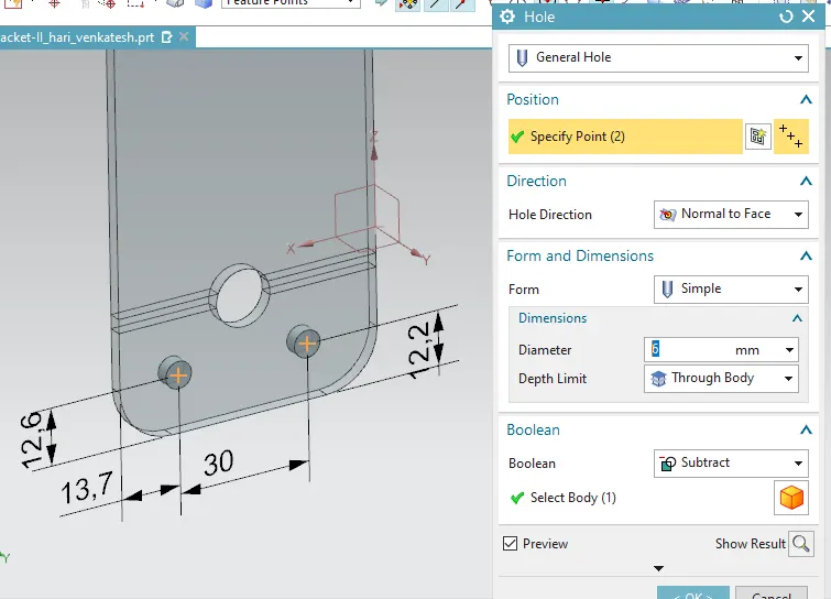
- Use the reference points to create holes by using inputs like hole type as general hole, form as simple, diameter size as 20 mm and depth limit as through body.
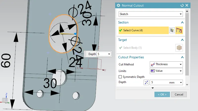
- To create a cutout at center the sketch it for given dimensions using sketch option in direct skecth tab.
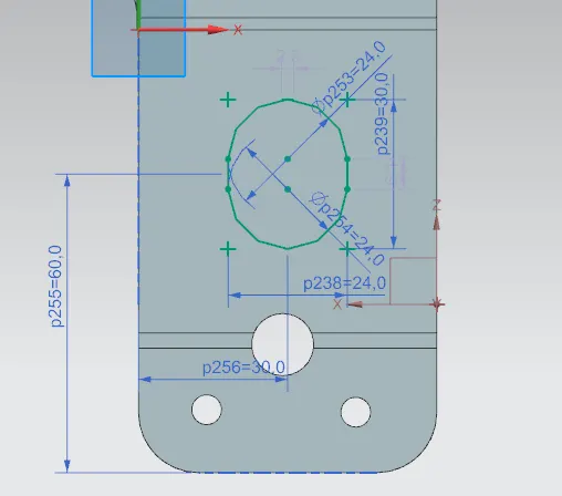
- Use normal cutout to trim the internal cut sketch for 5 mm depth.
5. Rebend the flat sheet to 3D sheet
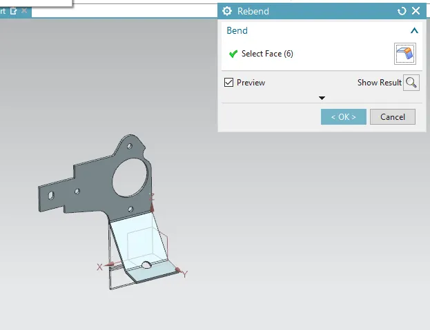
- Use rebend command to return the flattened sheet to 3D sheet design from rebend command in form tab by selecting the bend and flanges orderwise.
6. Break corners
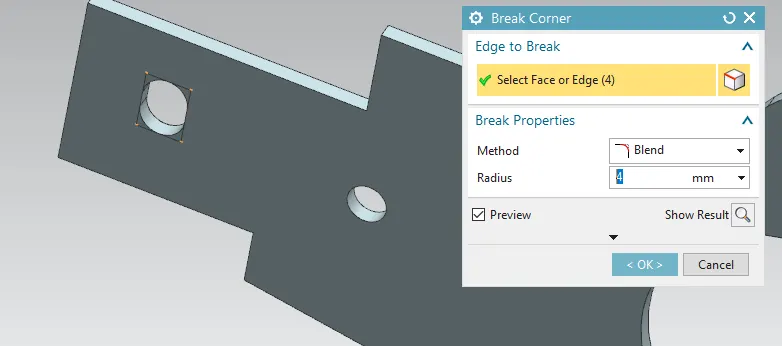
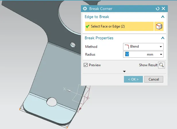
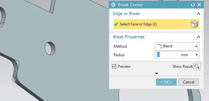
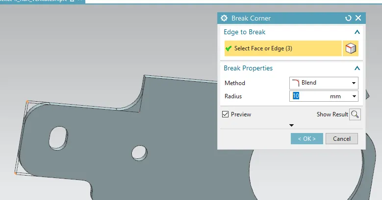
- The flanges has sharp edges use break corner from corner tab and radius value as 4 mm, 4.5 mm, 5 mm, 10mm & 12 mm respectively by refering the corners given.
7. Create advanced flange
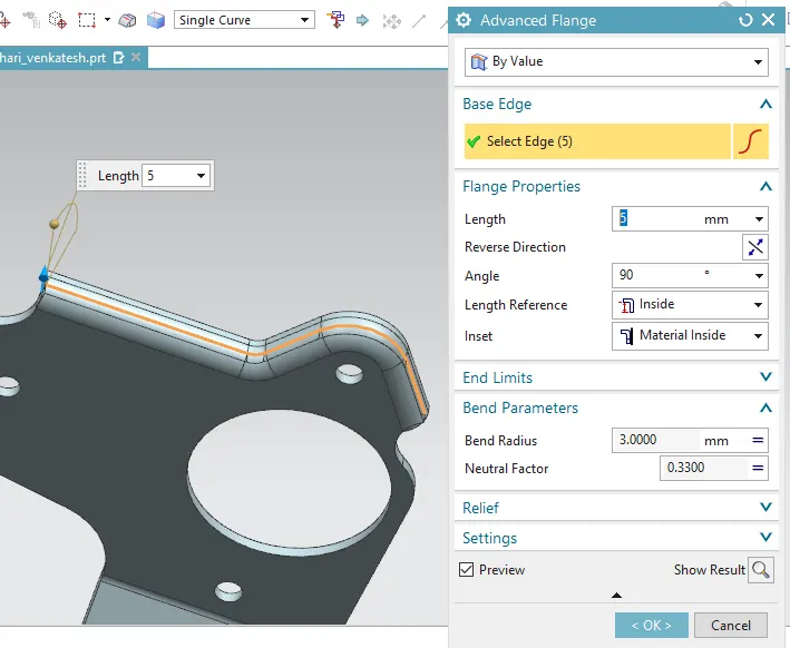
- Use advanced flange from bend tab > more > advanced flange and select the top curve for 5 mm length & other inputs as default.
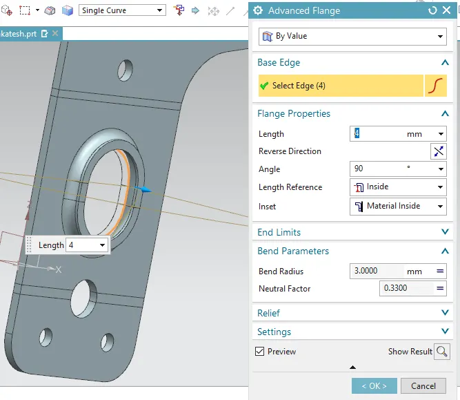
- Again create an advanced flange from bend tab > more > advanced flange and select the middle internal cut curve for 5 mm length & other inputs as default.
8. Gusset
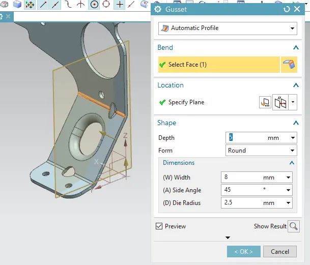
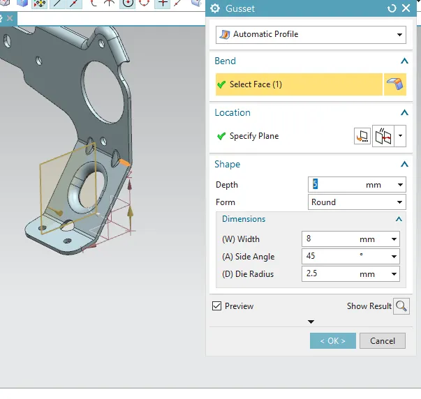
- Create two gussets at middle bend specified in image for 5 mm depth, 8 mm width, side angle of 45 degree and die radius of 2.5 mm.
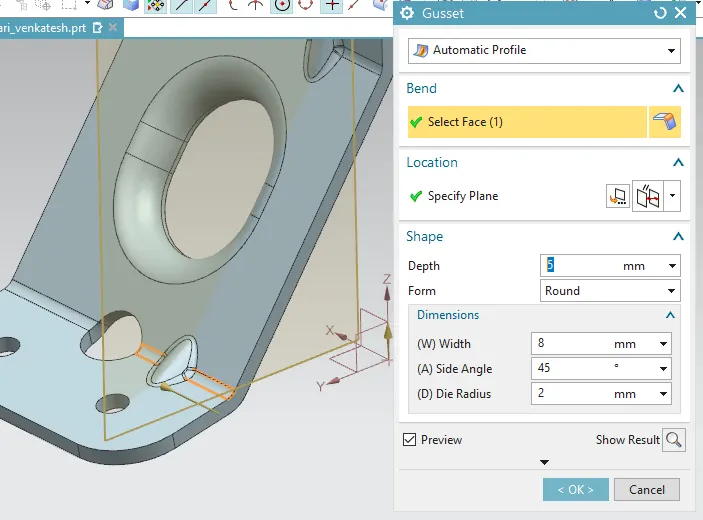
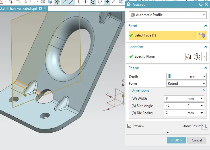
- Create two gussets at lower bend specified in image for 5 mm depth, 8 mm width, side angle of 45 degree and die radius of 2 mm.
RESULT:
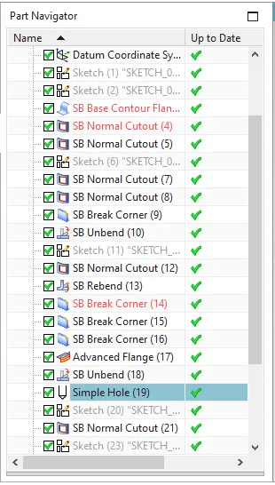
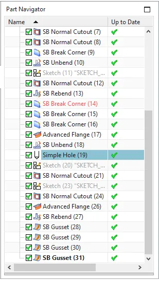
- Feature tree
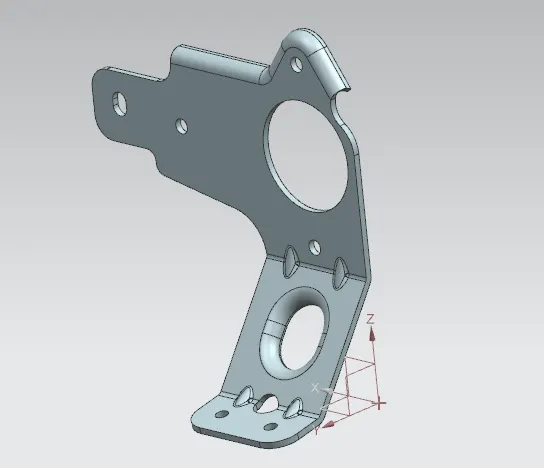
- Isometric view
- Top view
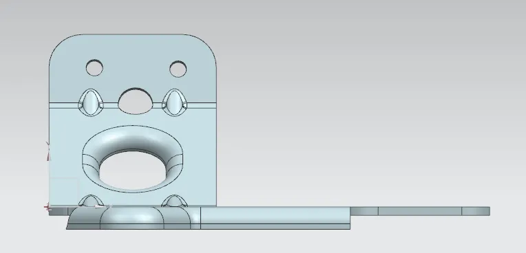
- Front view
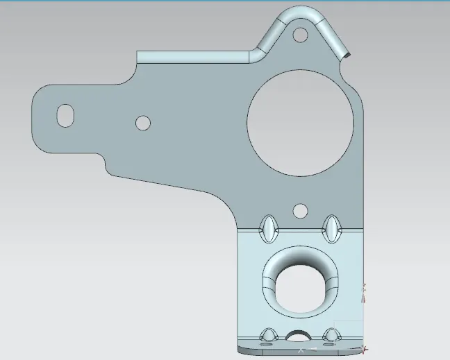
- Sideview