Advanced Sheet Metal Design Using NX Cad Challenge_7_ Metal bracket-II
Design of an Odd-shaped Metal Bracket of Advanced Sheet Metal Using NX Cad.
1. Objection: The Designing of an odd Shaped sheet metal parts using Siemens NX Sheet Metal. The main objectives of this project are conversation a 2D drawing into a sheet metal part, adding odd shapes to the part by using features and tools available in the NX Sheet metal application to achieve desired shape of the metal bracket.
2. Introduction: During this creation process, we are learning and using different types of tools and features available in the CAD application. This application has a lot of basic and advanced features such as Tab, flange, break corner, normal cut out, dimples, etc. The tool's flat pattern gives the manufacturer an idea about the material requirements positions of bends, and holes, and helps in the designing of the manufacturing process.
3. Design Methodology:
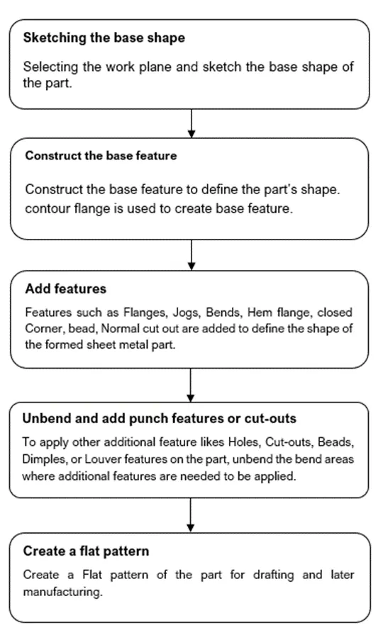
4. Description of the design process:
Step 1: Select the datum coordinate system → create a sketch as per the given dimensions → apply the contour flange to create the base metal sheet to add more features.
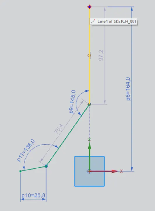
Sketch for contour flange.
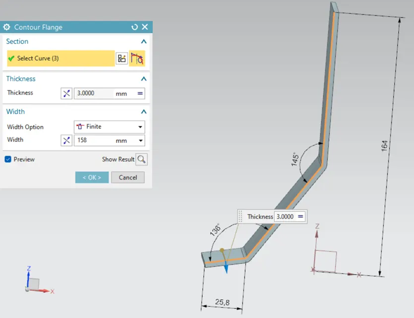
Contour Flange.
Step 2: To trim out the additional material from the created metal sheet → sketch the shape of the product on the surface of the sheet → apply the normal cut-out feature.
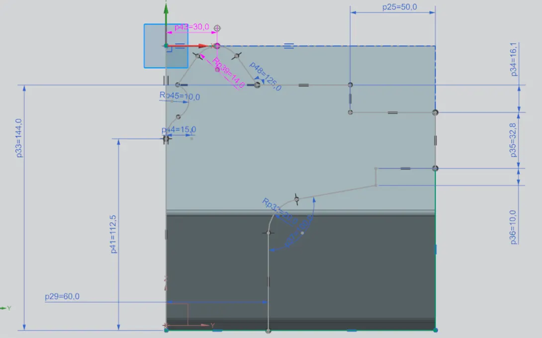
Sketch for the Normal Cut-out.
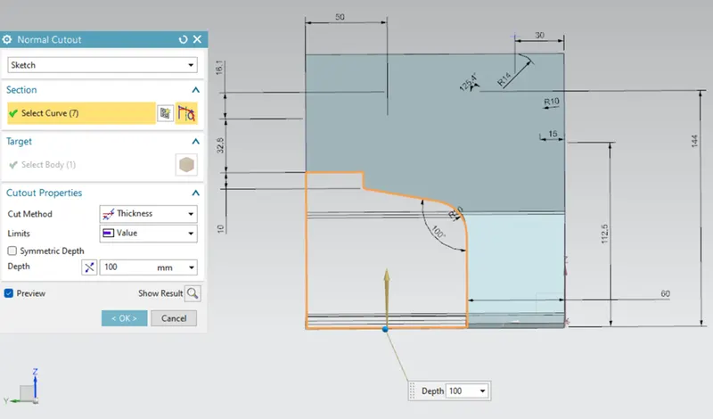
Normal Cut-out-1.
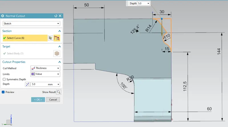
Normal Cut-out -2.
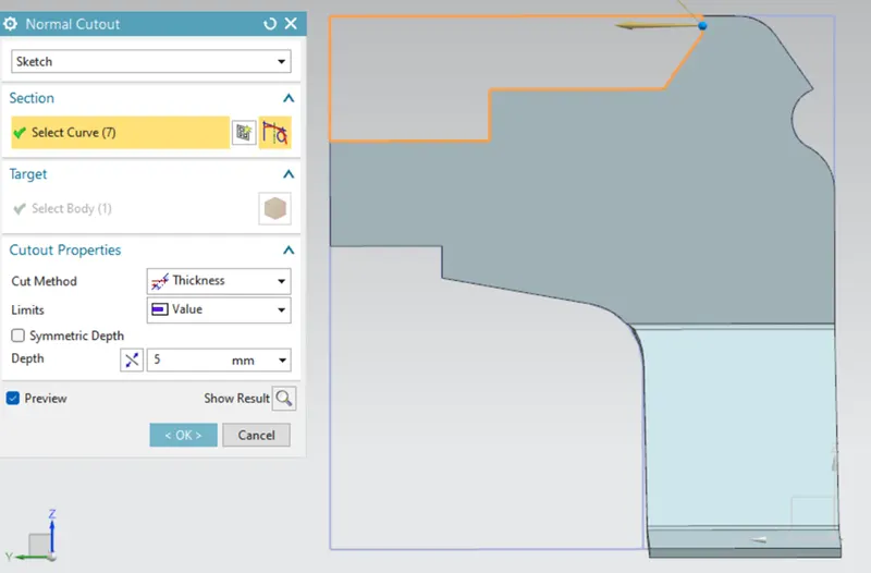
Normal Cut-out -3.
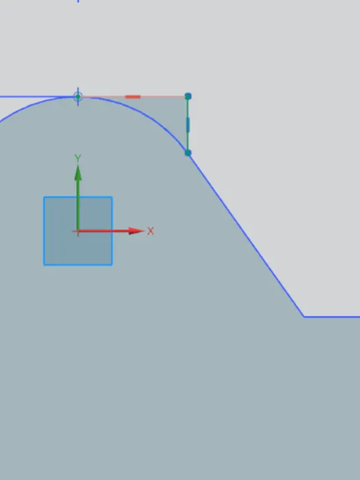
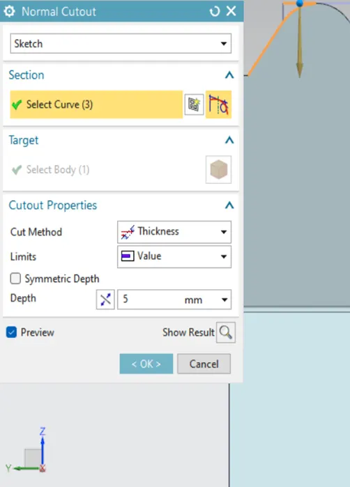
Sketch and Normal cut-out.
Step 3: To create holes and rectangular slots → sketch the curves on the surface of the sheet → apply the normal cut-out feature.
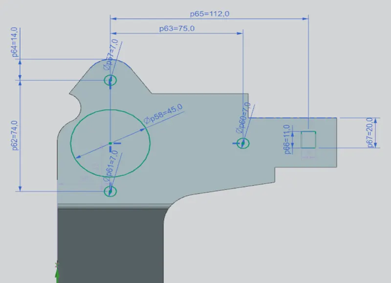
Sketch to create holes.
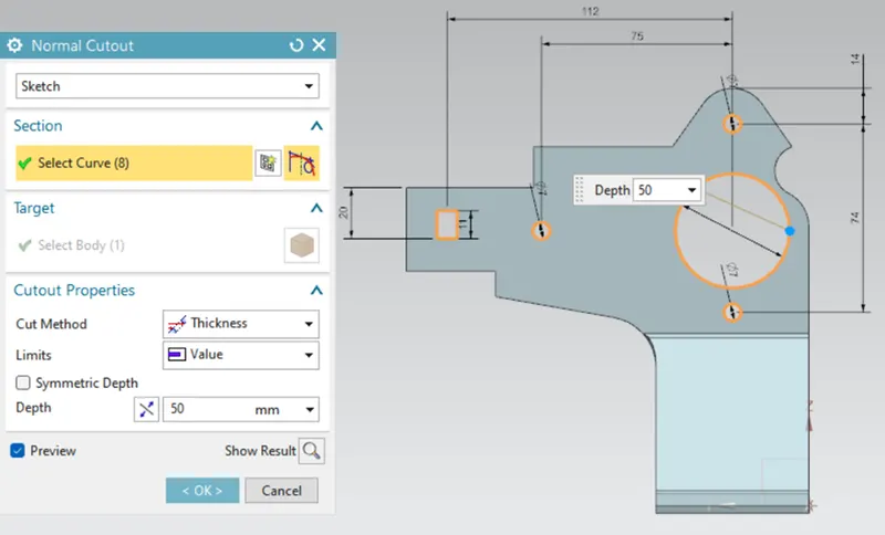
Normal cut-out.
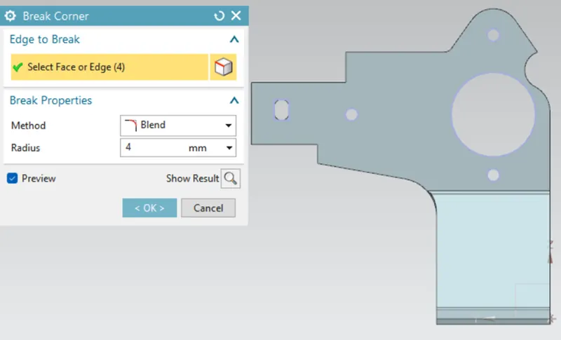
Break corner.
Step 4: To add furthermore features to the sheet → Apply the unbend → sketch a hole on the bend as shown in the figure → apply Rebend → apply the break corner to round the sharp corners.
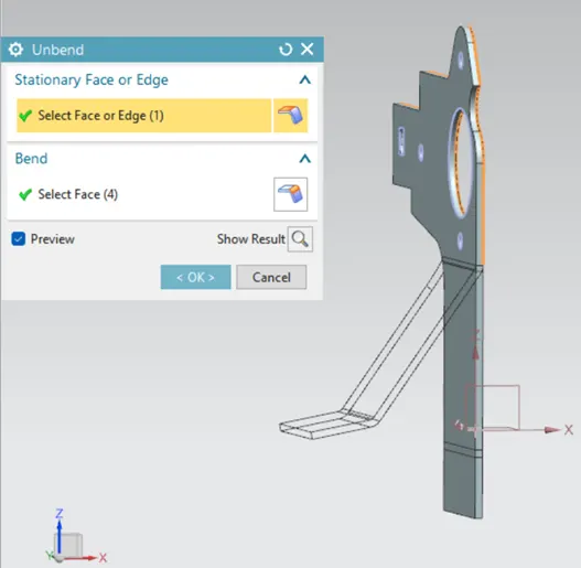
Un-bend.
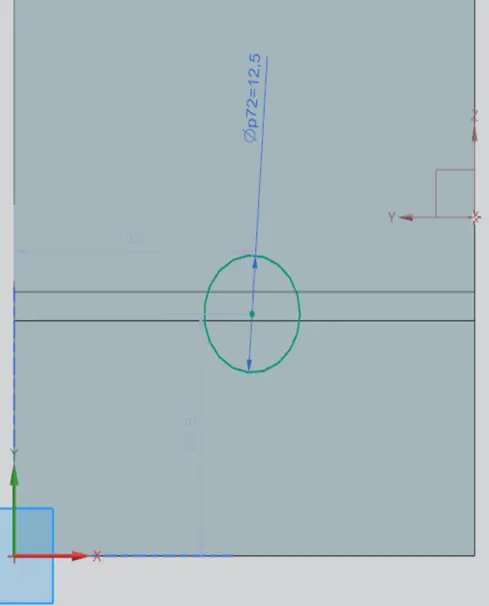
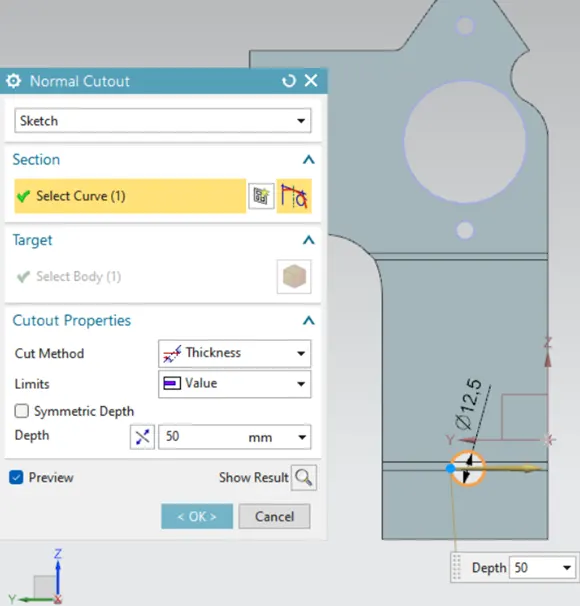
Sketch and Normal Cut-out.
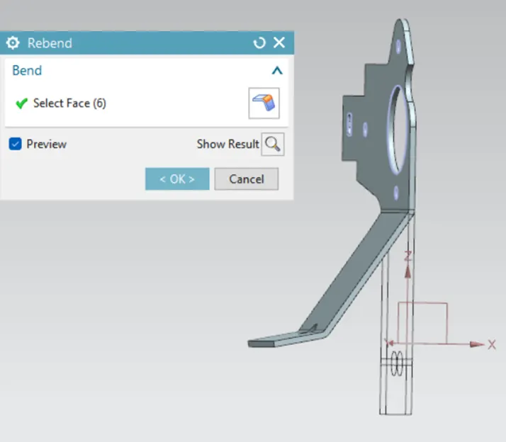
Rebend.
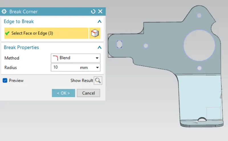
Break corner.
Step 5: The advanced flange feature is used to create the flanging around the round corners and edges. To select the advance flange feature → bend tools → more feature → advance flange. Select the edges → determine the value of the length of the flange and respective parameters and Apply.
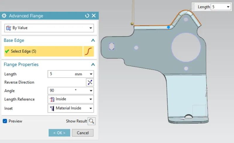
Advance flange.
Step 6: To add a few more designing elements to the sheet, perform the unbend feature and add features likes holes and normal cut-out as per the design requirements. After completion of the adding following features, apply Rebend.
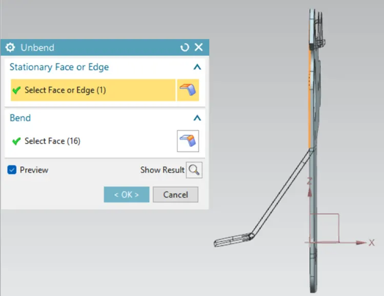
Unbend.
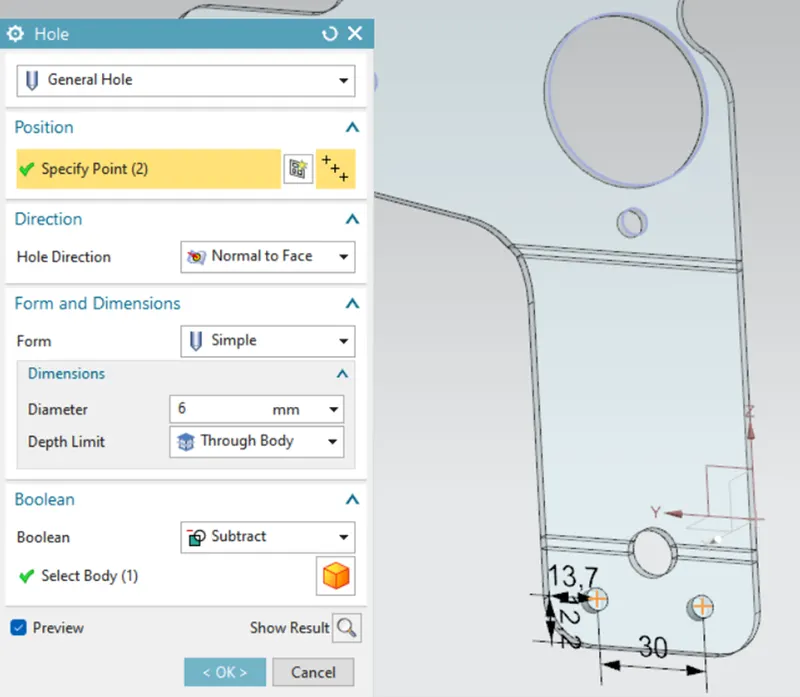
Sketch for the location of holes and simple hole feature.
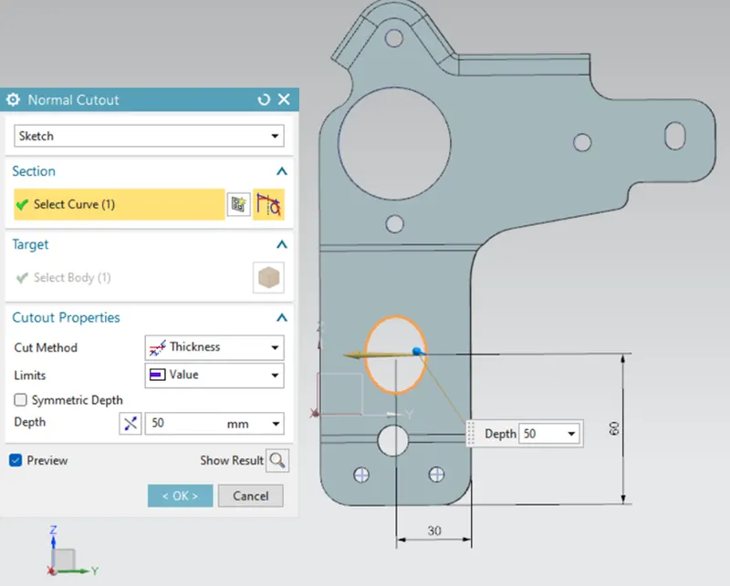
Normal cutout.
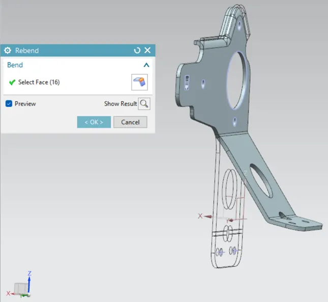
Rebend.
Step 7: Apply the advance flange to the above-created normal cut-out. To add stiffness to the design, add the Gusset feature.
Gusset Feature: Gussets are stiffening features created across a bend to reinforce the sheet metal part. Activate the Gusset command (click Home > Punch > Gusset on the ribbon) and click on a bend face. A gusset feature appears along with a Distance box attached to it. select the location of requirement.
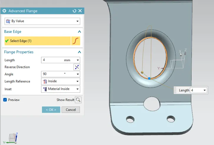
Advance Flange.
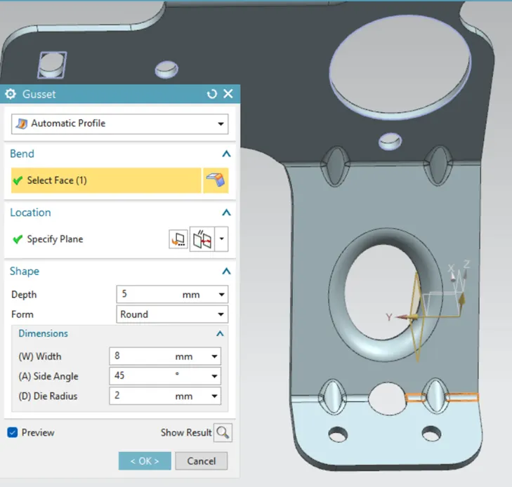
Gusset.
Views:
Isometric view:
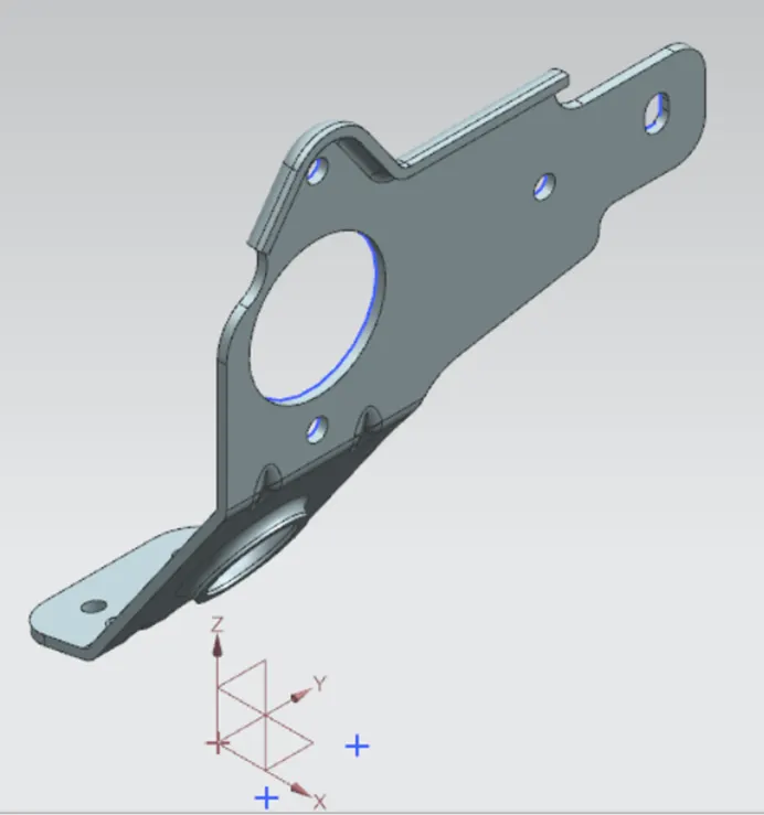
Isometric view.
Front View:
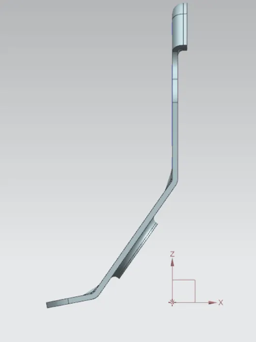
Front View.
Side View:
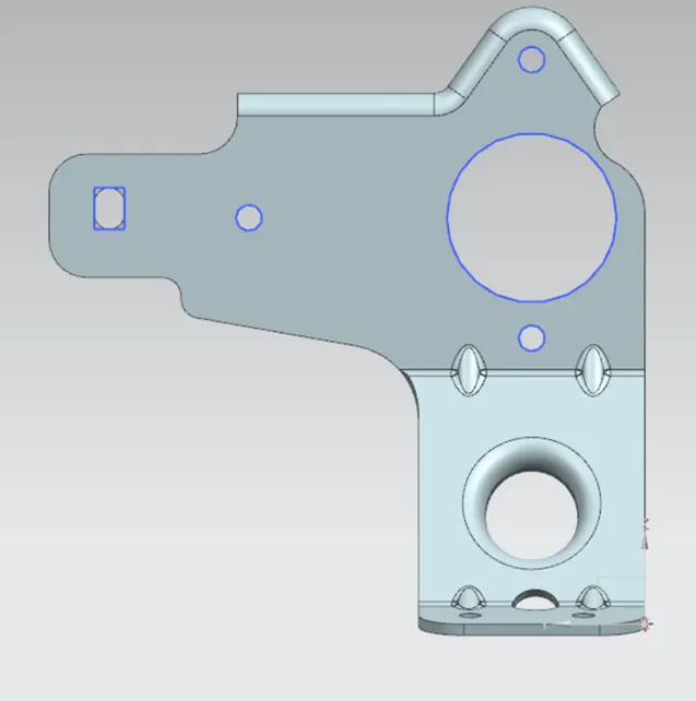
Side View.
Top View:
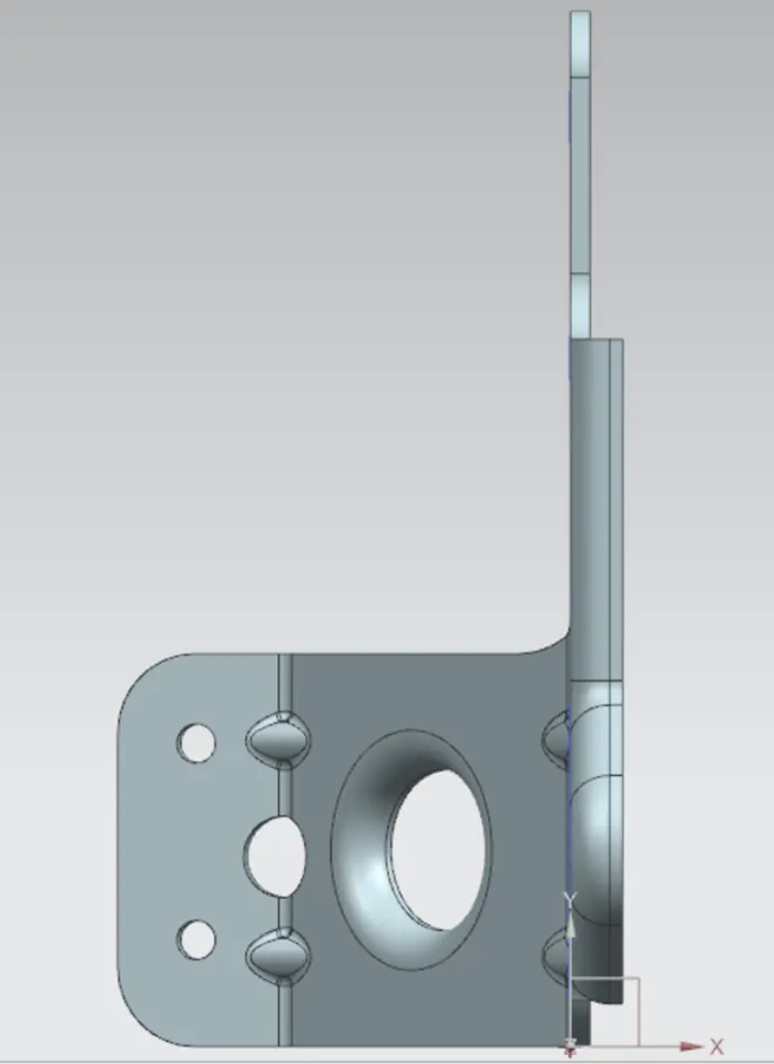
Top view.
Conclusion: The metal bracket is designed as per the design sheet requirements by using the features in the NX cad.