Photo Realistic Rendering
Modelling and Rendering of the American Chopper using Solidworks 2020.
1.Introduction:
Solidworks is the one of the leading 2D and 3D modelling software, and All in One platform developed by the Dassault Systems in the market. This CAD software helps to create models without any complexity, faster and in the cost-effective way. The Solidworks is also included with the ADD-INS like PhotoView 360, Solid modelling, Simulation, Assembly, CAM, e-drawing are the few options in it. We mainly used the assembly and the render tool in this model development. The assembly in the Solidworks will help the designers and the manufacturers to have the overview on the mating and overlapping of the different individual parts to make final model. The PhotoView 360 will bring the modelled part into the realistic appearances with the help of the material and data library, and help the designers make required changes, to make it more eye catching or more blend into the surroundings.
In this project, we mainly focused on the detailed design of American chopper parts, assembling, and rendering on the final assembly.
2. Objectives:
The main objectives of this project are:
- Designing of a chopper using various feature available in the Solidworks.
- To assembly all the individual parts to create complete American chopper.
- Rending final assembly with decals, lights, camera etc.
- To create photorealistic model and renders, using photoview 360 and Solidworks Visualize.
3. Software:
The software version used for creating Chopper:
- DASSAULT SYSTEMS SOLIDWORKS 2020.
- SOLIDWORKS Visualize professional 2020
4. Workflow Chart:
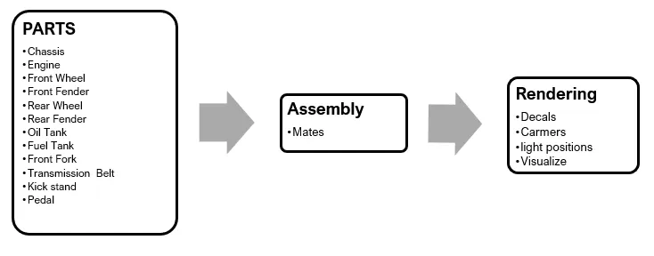
5. List of Features in Solidworks:
2D Sketch:
The Sketch is a 2D representation of the model. These are known as entities in Solidworks. e.g.: line, rectangle, spline, circle, elliptic, arc etc.
Loft:
The Loft feature allows you to generate complex geometry. It does this by interpolating surfaces between various cross section of the model. These cross sections can be sketches, faces or edges. In the Loft interface the cross sections are considered as Loft profiles.
Dome:
This feature is majorly applied to faces to give the semi-spherical shape. Select one or more planar or non-planar faces. You can apply dome to faces whose centroid lies outside the face. This allows you to apply domes to irregularly shaped contours.
Extrude Boss/Base:
This feature is used to convert a 2D sketch into 3D model.
Extrude Cut:
This feature is used to remove materials from the 3D mode. It is just opposite to extrude boss because it cuts a sketch profile while extruding. You can cut in both directions and mainly used for creating holes, channels slots etc.
Fillet:
This feature creates a rounded internal or external face on the part. You can Fillet all the edges of a face, edges, loops etc.
Split:
This tool is used to project an entity onto other surface or curved or planar faces. You can also split faces on multiple bodies with one command.
Offset:
Offset one or more sketch entities, selected model edges or model faces by specified distance. For e.g. You can offset sketch entities such as splines or arcs, set of model edges, loops and so on. You can offset finite lines, arcs, and splines.
Revolve:
Create a 2D sketch that contains one or more profiles and a Centre line or an edge to use as the axis around which the feature revolves tools.
Dynamic Mirror:
Dynamic mirror, it is used as you sketch the entities, they are mirrored about the pre-sketched sketch entity.
Shell:
The shell feature is used to define the thickness of thin and thick shell elements.
Combine:
Combine feature is used to manually combine two bodies like add, Subtract etc....
Trim entities:
You can make, save, edit, and insert blocks for drawing items and sketch entities that you use often, such as standard notes, title blocks, labels positions and so on. You can attach blocks to geometry or to drawing views and you can insert them into sheet formats.
Patterns:
The curve driven pattern tool allows you to create Patterns along a Planar or 3D curve. You can base your pattern on an open curve or on a closed curve such as circle. In the chain part curve driven pattern is used.
Chamfer:
An Angular cut on the edge or corner in either 2D sketch or 3D model to make slope slightly rather being perfectly right angle to each other.
Linear pattern:
The linear pattern, to create multiple instances of one or more features that you can space uniformly along the linear path.
Revolve cut:
Revolve
Circular Pattern:
Circular pattern is used to create multiple instances of web shaped Spokes around the Axial of the wheel. It is also used to create holes on the brake disc and thread design all around upper surface of the tire. This feature is more helpful in create multiple instances around the axis than mirror feature, saves time and is it has more flexibility.
Move/Copy Body:
This feature is used to move/copy the body from one place to another place.
Mirror:
By Using mirror faces with a midplane selected only the chosen faces within the revolve will be mirrored. Mirroring bodies can be used whether in a single or multibody part and allows you to select solid geometry instead of the features and faces in a body. In the fork part the one part is created, and the other part is mirrored. Then the parts are manually combined.
Projected curve:
Projected curve is a kind of 3D curve which is created from the two different 2D sketches to form a single complex curve, which can be used as a reference curve to create 3D model. 3D curves can also created by the intersection of two extruded surfaces generated by creating sketches on two intersecting planes.
Sweep:
Sweep creates a base, boss, cut or surface by moving a profile (section) along a path. A sweep can be simple or complex. Sweep geometry are created by a series of intermediate sections made by replicating profile at various position along the path.
Additional parameters can be included in the sweep feature such as guide curves, profile orientation options, and twist to create a wide variety of shapes.
Split:
Split is used to divide a part into multiple bodies. You can keep the bodies within the part or save them into separate part files. You can save them during the creation of the split feature, or use Save Bodies to save them after the spilt is complete.
Combine Manager:
Combine is used to specify multibody part to add, subtract, or overlap. The main difference between the assembly and combine is, in combine bodies contained within one multibody part file and cannot combine two separate parts. The combine has three operation types:
- ADD: - Combines solids of all selected bodies to create a single body.
- Subtract: - Remove overlapping material from a selected main body.
- Combine: - Remove all material except that which overlaps.
Composite Curve:
Features like sweep require that the path must be a single entity. It can be an edge, sketch, or a curve feature. When you have multiple entities, it can be combined using composite Curve feature.
Loft surfaces:
Loft surface feature is an important tool for surface modelling. This feature creates a shape by making transitions between multiple curves and the guide curves. This tool is very valuable for modelling complex surfaces.
Sweep Surfaces:
Sweep surface is a surface generating feature by moving 2D profile along a 2D or 3D sketch path.
Cut-Sweep:
Cut sweep come under the specifying modify parameters for boss. It is used to create the complex twisted or orientation cuts on the solid bodies.
Boundary Surface:
Boundary surface feature allows the user to create surfaces that are tangents or curvature continuous in both directions (all sides of the surface). This feature gives higher quality result than the loft tool.
Surface Trim:
Primarily used to cut away material from a surface and provides two modes: standard and mutual.
Surface Knit:
Surface knit tool combines two or more faces and surfaces into one. It creates a solid body when the knit surfaces form a closed volume or leave as a surface body.
6. Modelling of Individual Parts:
6.1. Kickstand:
The kickstand is used to support the chopper while resting in still. So, need to be properly based on the ground.
Features used to create Kickstand:
- 2D Sketch
- Loft
- Dome
- Extrude Boss
- Extrude Cut
- Fillet
- Split
- Appearances
Procedure to create a 3D model of Kickstand:
- open a new Solidworks part.
- Changed the default planes as follows:
- Front Plane - Front Plane.
- Top Plane - Top Plane.
- Right Plane – Mid Plane.
- Then 2D sketch is created in the front plane and fully defined with dimension, while sketching we use spline and trim commands.
- There are two new planes created and ellipse is drawn in the new plane as per the requirement.
- Then the loft command is used to create loft for the kickstand.
- The extrude cut is used to cut parts which are not required for the stand.
- Dome feature is applied to the bottom face of the kickstand to make the face round and smooth.
- Fillets are applied to edges and applied appearance.
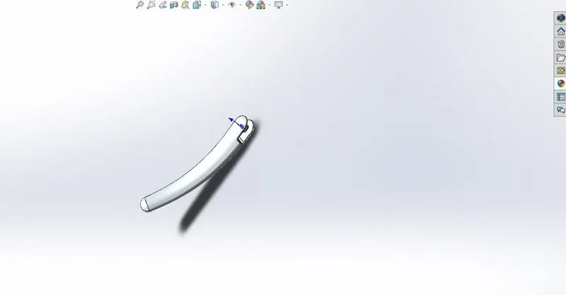
Fig: 1.1 Kick Stand
6.2. TRANSMISSION BELT:
Transmission belt transmits power from engine to gear box.
Feature to create Transmission Belt:
- Basic 2D Sketch
- Offset
- Extrude
- Fillet
- Appearances
Procedure to create a model of transmission belt:
- open a new Solidworks Part.
- The 2D sketch is created on the front plane and dimensions and relations are given to make the sketch fully defined. While sketching offset command is used to make a duplicate sketch to some distance.
- After this process, the sketch is closed. Then the extrude command is used to convert 2D sketch to 3D model.
- Then Fillet is given to the belt as per the given dimensions.
- Add the Appearances.
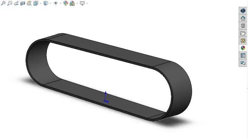
Fig: 1.2 Transmission Belt
6.3. FRONT FENDER:
The front fender is the mounted on the front fork above the wheel to protect the rider and the chopper other parts from the mud, stones, and foreign particles.
Features used to create Front fender:
- 2D Sketch
- Offset Entities
- Trim Entities
- Revolve
- Dynamic Mirror
- Split
- Fillets
- Appearances
Procedure to create a model of Front Fender:
- Create a reference Axis 1 inside of the revolving.
- Create a profile in the shape of the front fender cross-section and fully defined with dimensions.
- Use the revolve feature, select the profile and reference axis.
- To adjust arc length of the revolve part, used the direction1 and direction 2 to the desired values.
- Create a profile using spline and fully defined the profiles, and the feature split to remove the material from the revolve part to give nice pointing look at both ends of the front fender.
- Fillet is used create nice curvature all around the edges of the front fenders.
- Select the display manager to apply appearances.
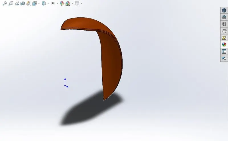
Fig: 1.3. Front Fender.
6.4. Rear Fender:
The use of rear fender is the same as front fender. The rear fender is mounted on the Chassis of the rear part above the Rear Wheel.
Features used to model Rear Fender:
- Sketch
- Offset Entities
- Trim Entities
- Revolve
- Split
- Shell
- Fillet
- Appearances
Procedure to create a model of Rear Fender:
- Created a reference line that through the origin inside of the revolving.
- Created a profile in the shape of the rear fender cross-section and fully defined with dimensions.
- Used the revolve feature, select the profile and reference axis.
- To adjust arc length of the revolve part, used the direction1 and direction 2 to the desired values.
- Created a profile using spline and fully defined the profiles, and the feature split to remove the material from the revolve part to give nice pointing look at both ends of the rear fender.
- Fillet is used create nice curvature all around the edges of the rear fender.
- Used the shell feature to created stepping of face on inner side of the rear fender.
- Select the display manager to apply appearances.
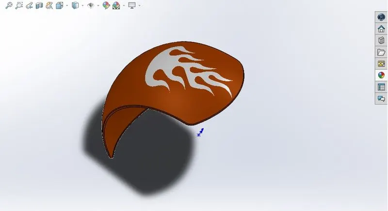
Fig: 1.4. Rear Fender.
6.5. Chain:
The chain is connecting link between the sprocket wheel on the rear and the sprocket that comes from the gear box in the power transmission system of the engine. The shape of teeth of the sprocket wheels, distance between the centre of the sprocket wheel determines the size of the chain (width, dia of the roller, pitch of the chain links), number of chain links, the overall length of the chain.
Features used to create Chain:
- 2D Sketch
- Trim
- Fillet
- Blocks
- Extrude
- Patterns
- Appearances
Procedure to create a model of Chain:
- Draw the path sketch of the chain on the Mid Plane chain and fully defined the sketch. This curve path is used as reference in the Pattern feature.
- Draw the 2D sketch of basic chain links on the mid plane, that are duplicated nth times along the chain path.
- Used the boss extrude feature and offset feature in the boss extrude to convert 2D into links plates and pins. The fillet is applied to outer edges of the pins.
- Used curve driven pattern feature to duplicate the above creates boss extrude links and pins, till one link distance before ending of the 1st segment of the curve.
- Repeated the above steps 2, 3, and 4 for each segment of the curve.
- The final link is created between 1st and last pins of the chain to make close.
- Mirror feature is used to complete the chain and Select the display manager to apply appearances.
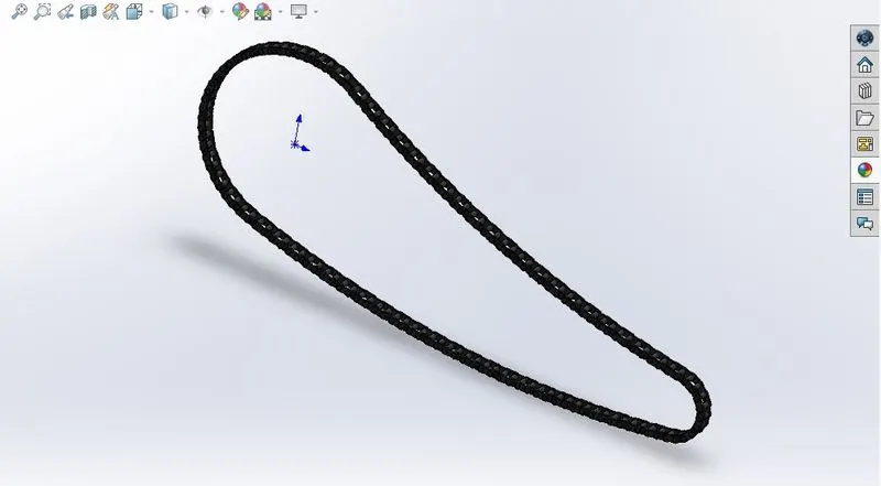
Fig: 1.5. Chain.
6.6. OIL TANK:
The oil tank is used to store the lubricant oil required to run the Engine smoothly. It is a hollow one inside to store the oil. The thickness of the oil tank is given by 3 mm in our chopper model.
Features used to create oil tank:
- 2D Sketch
- Boss Extrude
- Combine
- Fillet
- Shell
Procedure to create a model of Oil tank:
- Created the 2D sketch on the top plane using the lines and arcs based on the given dimensions.
- Boss-Extruded the sketch.
- Created the other 2D sketch on the Mid-plane of oil tank and boss-extruded the sketch.
- In Combine feature, the common feature is used to create the final shape of the oil tank.
- The shell feature is used to create the hallow space inside the tank to store and the fillet are applied to give round and smooth edges.
- Select the display manager to apply appearances.
- The decal is applied on the front face of the oil tank in later phases of the design work to give modern look.
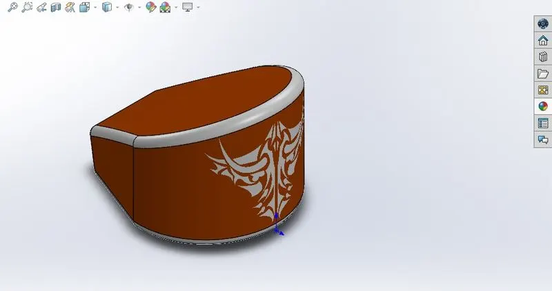
Fig: 1.6. Oil Tank.
6.7. PEDAL:
Pedal is the external part attached to the chassis. The pedal is used to rest the leg on top of that to give comfort to the rider and its robust appearance in chrome plate gives the super look the chopper.
Features used to create Pedal:
- 2D Sketch
- Extrude
- Fillet
- Linear Pattern
- Dome
- Chamfer
Procedure to create a model of Pedal:
- Created 2D sketch on the front plane using lines, arcs, circle and spline of a given dimensions.
- Applied boss extrudes few times on the profiles.
- Applied fillet, Chamfer and dome to create good look.
- To provide grip to the foot, rings are created by using linear pattern.
- All the individual created parts are added into one single part by using Combine feature.
- Select the display manager to apply chrome metal appearance.

Fig: 1.7. Pedal.
6.8. FRONT WHEEL:
A wheel is combination of various parts modelled all together into one model. It has different parts like Rim, Tire, Brake Disc, and Caliper. These parts are having different materials and appearances for different functionalities e.g., the tire surface is modelled along with special thread design to increase tractions.
Features used to create Front Wheel:
- 2D Sketch
- Revolve
- Trim
- Fillet Sketch
- Boss Extrude
- Revolve Cut
- Linear Pattern
- Chamfer
- Cut Extrude
- Circular Pattern
Procedure to create a model of Front wheel:
- Created the profile of the front wheel rim and centre hub on the front plane.
- Used revolve feature to create the rim and centre axial hub.
- To create support spokes between rim and hub, a profile is created on the right plane and boss extruded.
- To have fashionable look the web shaped design is selected. Boss extrude, cut extrude, cut revolve, and trim feature are used in the designing of it.
- Circular pattern is used to create two more spokes.
- To create brake disc and caliper, sketch is created on right plane » boss extruded » cut extruded the holes on the disc » curve pattern the holes on the disc plate » cut extruded the slots on to disc.
- To create tire, sketched the tire profile » revolved around the rim » created the threading on the surface » cut extruded threads on to the surface of the tire » circular pattern the threads.
- Add respective appearance to respective parts.
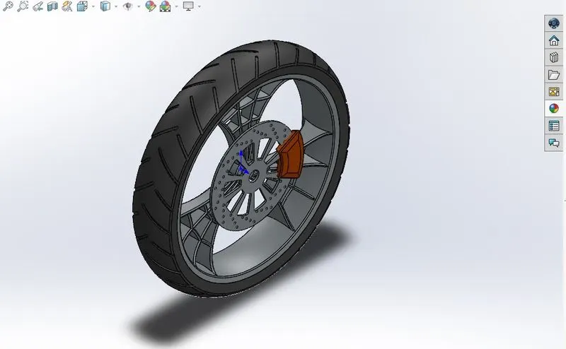
Fig: 1.8. Front Wheel.
6.9. REAR WHEEL:
A Rear wheel drives the chopper with the configuration of Engine power, Transmission belt, chain, and Rear wheel deliveries the power from the chopper to the ground, which drives the chopper froward.
The Rear Wheel model consider of rim, tire with special traction thread design, caliper, brake disc and Socket wheel.
Features used to create Rear Wheel:
- Sketch
- Revolve
- Trim
- Sketch Fillet
- Extrude Boss
- Planes
- Revolve cut.
- Linear Pattern
- Chamfer
- Fillet feature
- Extrude Cut
- Circular Pattern
Procedure to create a model of Rear wheel:
- Created the profile of the rear wheel rim and centre hub on the front plane.
- Used revolve feature to create the rim and centre axial hub.
- To create support spokes between rim and hub, a profile is created on the right plane and boss extruded.
- To have fashionable look the web shaped design is selected. Boss extrude, cut extrude, cut revolve, and trim feature are used in the designing of it.
- Circular pattern is used to create two more spokes.
- To create brake disc and caliper, sketch is created on right plane » boss extruded » cut extruded the holes on the disc » curve pattern the holes on the disc plate » cut extruded the slots on to disc.
- To create sprocket plate, sketch is created on the out face of the central axial hub » boss extruded » chamfer » cut extrude the teeth on to the plate » circular pattern teeth all around the plate » sketch and cut extruded the slot on the plate » circular feature is applied to slots » fillet feature wherever required.
- To create tire, sketched the tire profile » revolved around the rim » created the threading on the surface » cut extruded threads on to the surface of the tire » circular pattern the threads.
- Add respective appearance to respective parts.
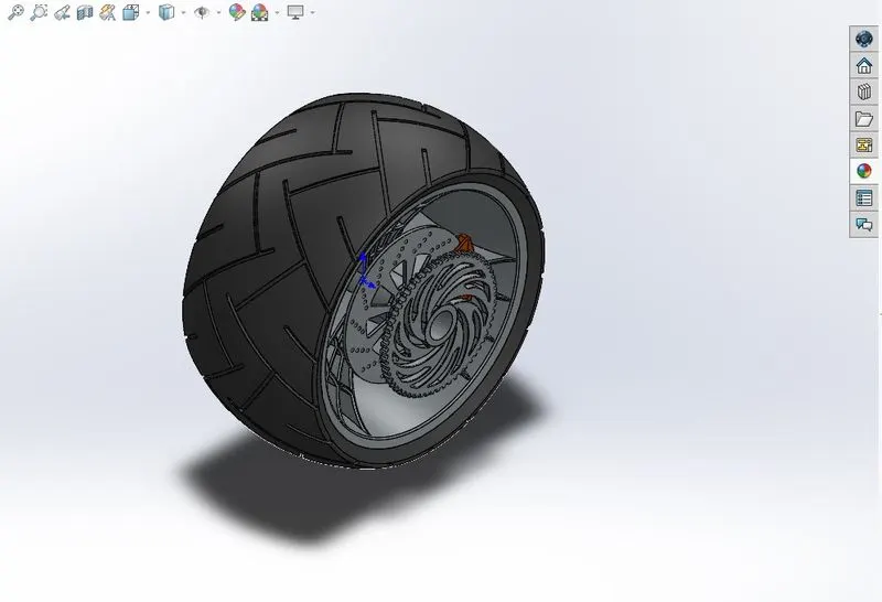
Fig: 1.9. Rear Wheel
6.10. FRONT FORK:
Most motorcycles today use telescopic forks for the front suspension. The forks can be most easily understood as simply large hydraulic shock absorbers with internal coil springs. They allow the front wheel to react to imperfections in the road while isolating the rest of the motorcycle from that motion.
Features used to create Front Fork:
- 2D Sketch
- Extrude
- Trim
- Revolve
- Split
- Move/Copy bodies
- Dome
- Mirror
- Combine
- Projected curve
- Sweep
Procedure to create a model of Front fork:
- Created the profile of the side leg of the fork and used revolve feature.
- Created the base for the triple tree design on the top face of the fork leg and boss extruded by using offset option in the feature » linear pattern for other one.
- Axial is created by boss extrude.
- Head lights are created by using revolving feature » moved to its position » cut extruded the glass face » applied dome feature » fillet.
- Handlebar is created by, sweep the circular profile through the curve path » a plane 1 is created inline to the sweep » the handle grip is created by revolving » a plane 2 is created with an angle to plane 1 » clutch bar profile is created, and boss extruded.
- To create clutch cable, projected curve feature is curved to develop 3D curve from 2D curves » sweep through the length of the projected curve » combine feature » mirroring feature.
- Added appearances to the parts.
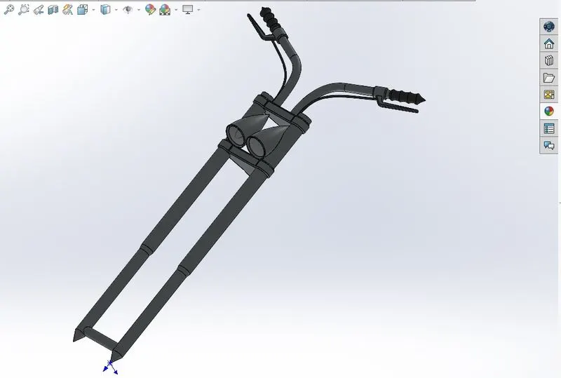
Fig: 1.10. Front Fork.
6.11. CHASSIS:
A chassis is the main structural frame of the chopper, it provides platform for all other components such as Engine, gas tank, wheels, suspension etc to assembled. The design of the chassis will influence the final outlook and handle ability of the motorcycle. The chassis is major developed from the composite curves.
Features used to create Chassis:
- 2D Sketch
- Offset
- Convert Entities
- Project Curve
- Trim
- Sweep
- Split
- Revolve
- Cut Extrude
- Fillet
- Combine
Procedure to create a model of Chassis:
- To have the reference to create the composite curve the blueprint of the chopper is imported.
- The curves are created on mid, bottom and right planes » projected curves are used » respective circular profiles are created at the end of the created projected curves and sweep is used to create hollow pipes structures.
- Support plates and rear axial shaft are created by boss extruded and revolve respectively to mount the engine and fix rear wheel on to the Chassis.
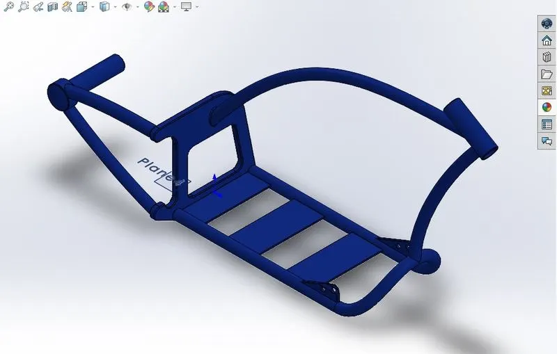
Fig: 1.11 Chassis.
6.12. ENGINE:
Engine is the powerhouse for the bike. The engine, that is designed is a twin V-shape petrol model along with other major components such as gear box, start motor, air filter, exhaust system. The Belt pulleys on the right side of the engine along with the transmission belt, transmit the power from crack shaft to gear box, and from the gear box to rear wheel with help of chain.
Features used to create Engine:
- 2D Sketch
- Trim
- Revolve
- Boss Extrude
- Extrude Cut
- Offset
- Dome
- Fillet
- Projected Curve
- Composite Curve
- Sweep
- Mirror
- Circular pattern
- Split
Procedure to create a model of Engine:
- Created the crank case of the engine by drawing profile on the front plane » boss extrude in both directions.
- Boss extruded the gear box » revolve feature for creation of pullies for the transmission belt. The teeth on the pullies are created by boss extrude and circular pattern on both.
- The starter motor is created by boss extrude.
- Cylindrical blocks by using following sequence of steps: Plane creation » boss extrude » chamfer » fillet » cut extrude » linear pattern » boss extrude » dome.
- Mirror and combine the created cylindrical block to form V-shape twin engine.
- Created composite curves and used sweep feature to design exhaust system.
- The air filter is created by revolve feature » cut extrude » fillet.
- Combine feature to add all the designed part into a single part.
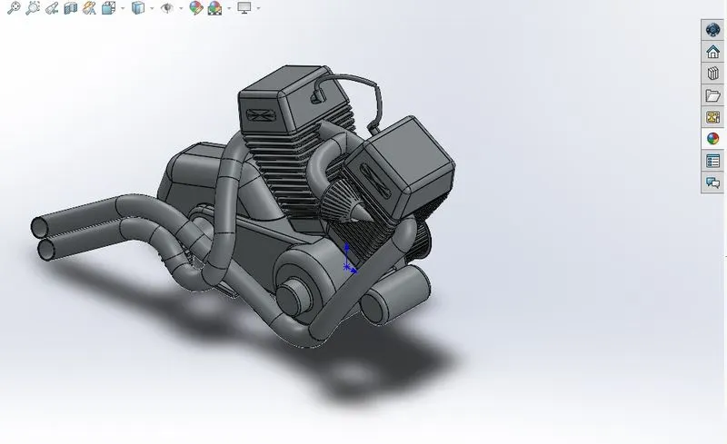
Fig: 1.12. Engine.
6.13. GAS TANK:
Gas tanks are used to store gasoline for the chopper. Gas tank is mostly created by using surface property manager like surface sweep, surface trim, surface trim etc.
Features used to create Gas tank:
- Trim
- Projected curve
- Surface Sweep
- Surface Loft
- Boundary surface
- Mirror
- Surface Trim
- Knit Surface
- Cut Sweep
- Fillet
Procedure to create a model of Gas tank:
- Created a new plane parallel to the front plane at the starting point of the tank. Curves are created on the plane1 and mid plane, surface sweep feature is used create the surface.
- To trim unnecessary surfaces, a curve is created on the bottom plane and surface trim feature is used.
- The surface loft is used to create surface on the side of the tank by using the profile and guide curve.
- The boundary surface is used to create the curvature surface from the curves.
- Mirror feature is used to form other half of the gas tank.
- All the surface are merged into one using Knit surface.
- The bottom side surface of the tank is created by following sequence of steps: boundary surface » surface loft » surface knit to close the tank and formed solid body.
- Boundary surface is used to create the seat.
- Cut sweep is performed on the bottom side of the tank to create fitting space for the chassis during assembling process.
- Fillet the edges and Shell feature to create hollow space to store gasoline.
- Appearances are applied to individual parts.
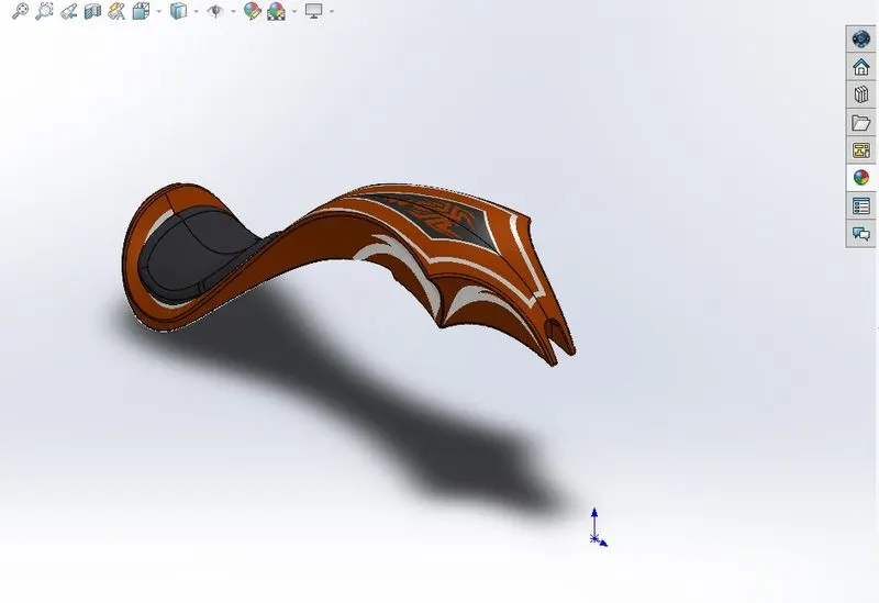
Fig: 1.13. Gas Tank.
- ASSEMBLY OF THE CHOPPER:
Assembly helps us make a complex model from models previously created in the part.
Features used to assemble chopper:
- Inserting Parts
- Mates
Mates:
Mates create geometric relationship between two or more individual components, which fully defines and limits the degree of freedom. As we add mates, we define the position, orientation and rotational motion of the components.
List of mates used in the Assembly are:
Standard Mates:
- Concentric
- Coincident
- Distance
- Angle
- Perpendicular
- Parallel
- Tangents
Advanced Mates:
- Limit angle
- Width
- Profile Centre
- Symmetric
Mate Alignment:
- Aligned
- Anti-Aligned
Procedure to create an Assembly:
- Open the new assembly file » select the insert components to import the part into the assembly platform.
- As chassis is the main frame to which all the parts are positioned and fixed.
- A chassis is imported and fixed with the coordinates of X, Y and Z, and engine, kick stand, Pedal, oil tank, rear wheel, rear fender, front wheel, front fender, front fork, transmission belt and chain are imported and are all the fully fixed on the chassis with the mates.
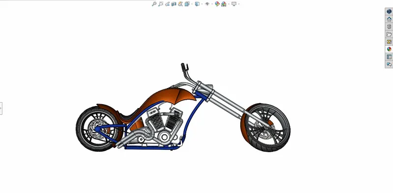
Fig: 1.14. front view of Assembly
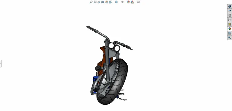
Fig: 1.15. side view of Assembly.
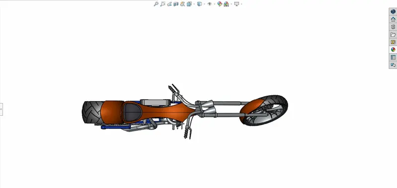
Fig: 1.16. top view of assembly.
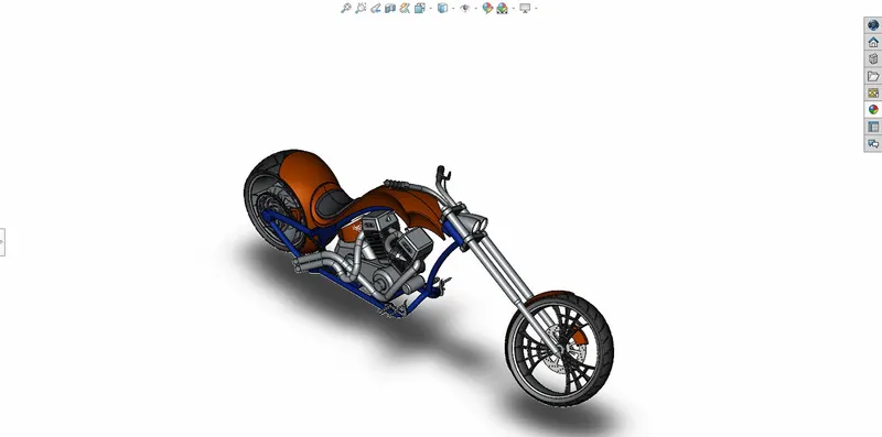
Fig: 1.17. isometric view of Assembly.
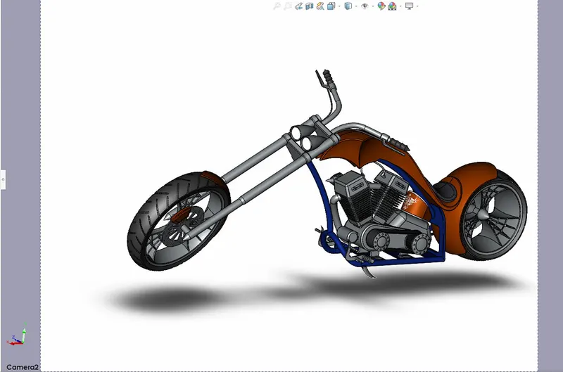
Fig: 1.18. Camera view of assembly.
8.Rendering:
- Rendering is a process of creating graphics, decals and logos on the model, and adding the environment effects to make model more realistic to the real-one.
- The rendering has been done in two ways in Solidworks:
- Photoview 360
- Solidworks Visualize
In the photorealistic model some of the mate conditions and positions are changed to render realistic models. Then, the photorealistic model is rendered into realistic images with different views.
8.1. Photoview 360:
Photoview 360 is a rendering tool with the features of appearance, scene, decal and options of adding cameras, spotlights, directional lights and ambient environments to the background. These features provide an interactive environment for viewing and create realistic images.
Fig: 1.19. Chopper rendering
8.2. Solidworks Visualize:
Solidworks Visualize provides a suite of stand-alone software tools that combine industry leading rendering capabilities with visual design-oriented features and workflows, allowing easy and fast creation of visual content that communicates a designs vision, passion, and emotion.
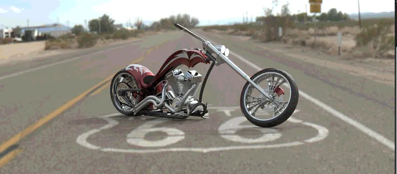
Fig; 1.19. Rendering of chopper on route 66.
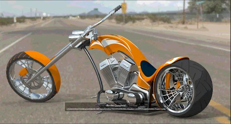
Fig: 1.20. Rendering of chopper
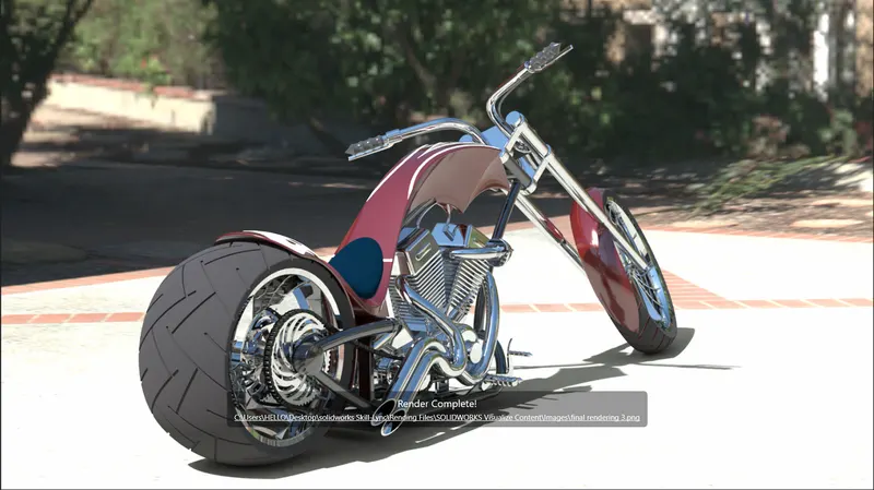
Fig: 1.21. chopper in Sunny Driveway.
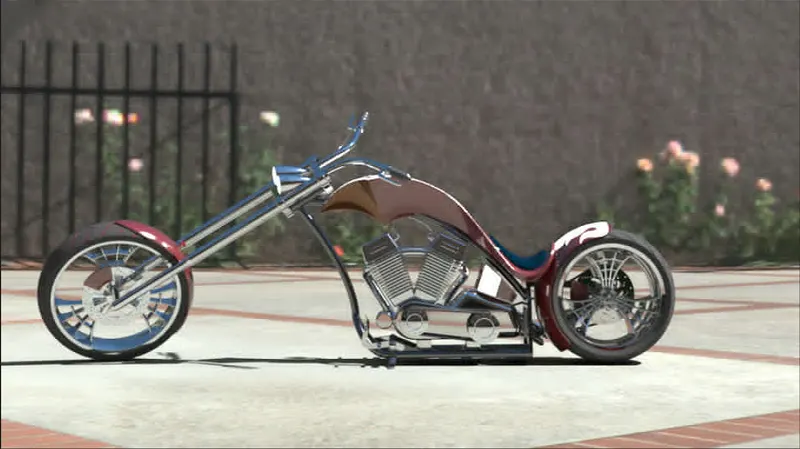
Fig: 1.22. chopper side view.
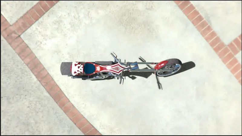
Fig: 1.23. chopper top view.
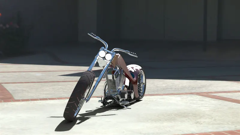
Fig: 1.24. Chopper rendering.
9. CONCLUSION:
- The individual parts of the chopper are modelled.
- The parts are inserted into the assembly and chopper is assembled.
- The decals are added to the surfaces and lights are rendered with the use of the photoview 360 and Solidworks Visualize.