Advanced Sheet Metal Design Using NX Cad Challenge_1_Casing Design
Application of Siemens NX Sheet metal tool and basic features in Design of a Sheet Metal parts
- Objective:
Designing a sheet metal part using some features of siemens sheet metal such as ‘Tab’, ‘Flange’, ‘Contour Flange’, ‘Break corner’, ‘Dimple’, ‘Hole’, ‘Unbend’, ‘Rebend’ etc.
- Introduction:
Sheet Metal Fabrication is the process of forming parts from a metal sheet by punching, cutting, stamping, and bending etc. sheet metal parts are known for their durability, which makes them great in the application of making chassis, PC cases. Other advantage of the sheet metal fabrication is more cost-effective for both low volume prototypes, and high-volume production runs.
2.1 Sheet metal design (CAD model): Sheet metal design is the process of designing and engineering sheet Metal into equipment, parts, Assemblies, and products from a uniform thickness metal sheet. This 3D CAD model is used for the preview of sequence of the fabrication steps.
2.2 Sheet metal design Guidelines:
The following are the terminology of the critical dimensions.
2.2.1. Bend line: - The straight line on the surface of the sheet, on either side of the bend, that defines the end of the level flange and the start of the bend.
2.2.2. Bend radius: - The distance from the bend axis to the inside surface of the material, between the bend lines.
2.2.3. Bend angle: - The angle of the bend, measured between the bent flange and its original position, or as the included angle between perpendicular lines drawn from the bend lines. Sometimes specified as the inside bend radius. The outside bend radius is equal to the inside bend radius plus the sheet thickness.
2.2.4. Neutral Axis: - The location in the sheet that is neither stretched nor compressed, and therefore remains at a constant length.
2.2.5. K-factor: - The location of the neutral axis in the material, calculated as the ratio of the distance of the neutral axis T, to the material thickness t. The K-factor is dependent upon several factors (material, bending operation, bend angle, etc.) and is greater than 0.25, but cannot exceed 0.50. The theoretical calculation approach is K-factor = T/t. The more accurate practical approach is state below:
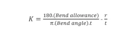
2.2.6. Minimum bend, r: - The minimum bend radii depends on the material, field of application (such as aerospace, PC frames, Space, etc.). In general, the recommended inside bend radius for soft material parts should be equal to material thickness and for hard material, inside bend radius equal to 0.65 times of sheet thickness.
If the minimum bend radius is less than the required values of the material, it may result in material flow problems in soft materials and fracturing in hard material.
2.2.7. Minimum flange Length, b: - The minimum recommended sheet metal flange bend length to avoid cracks in the bending area.
Minimum sheet metal flange bend length = 3* sheet metal thickness + Bend radius.
2.2.8. Bend Relief: - A bend relief is an incision cut along the sides of a planned bend. The main goal of the bend relief is to prevent tearing and part deformation during the bending process. In the below figure shows three different bend relief in figure ‘A’ shows a torn part, figure ‘B’ shows a part with the edge a sufficient distance from the form, figure ‘C’ shows a bend relief cut into the part. The recommended depth of the relief should be greater than the radius of the bend, and the width of the relief should be equal to sheet thickness or greater.
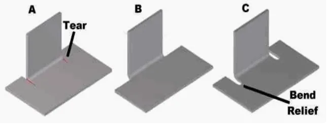
Bend relief
2.2.9. Sheet metal hole diameter guidelines: -
Minimum Hole Diameter: - The minimum hole diameter is recommended to remove, the practical difficult during fabrication by piercing process. In general, the diameter of the hole should be equal or more than the thickness of the sheet metal.
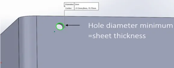
Minimum Hole Diameter
Forming Near Holes: - When a bend is made too close to a hole, the hole may become deformed. In the below, figure A, show a hole is deformed near the bend. So, a minimum distance should maintain from the bend to prevent deform of the hole. The following formulas are used to calculate the minimum distance for the hole and slot:
- For a hole < 25 mm, diameter, the minimum distance “D” = 2T + R.
- For a slot or hole > 25 mm, diameter, then the minimum distance “D” = 2.5T + R.
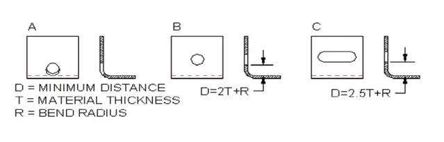
Guideline for the holes and Slots
Minimum distance from extruded hole to part edge: - Extruding metal to create holes is an operation which generates a lot of friction and heat due to application of extreme pressure in the process. If the extruded holes are too close to the part edge, it will result in the deformation or sometimes tearing of the metal. So, to avoid the deformation, the minimum distance of three times the sheet metal thickness (3*t).
- Design methodology:
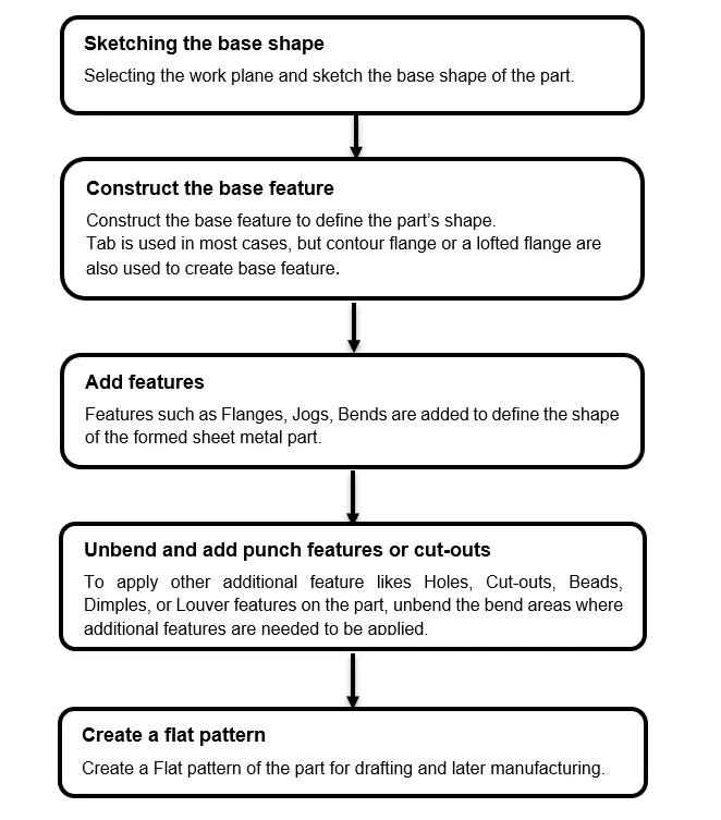
- Description of feature in sheet metal design:
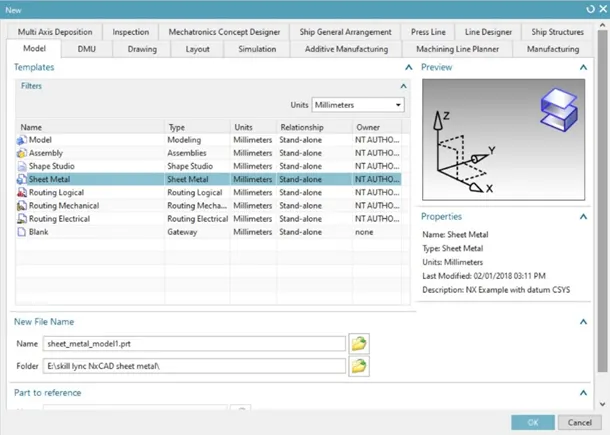
Step 1: Open the siemens NX → select the file from the menu → select the new file or use shortcut CTRL + N → select the sheet metal as file type → save the file with project name and in desired folder → Select the menu, preferences, sheet metal and set user requirements as default → select the datum CSYS → Select the sketch icon in the menu, Orient the plane → Draw the sketch according to the given dimensions.
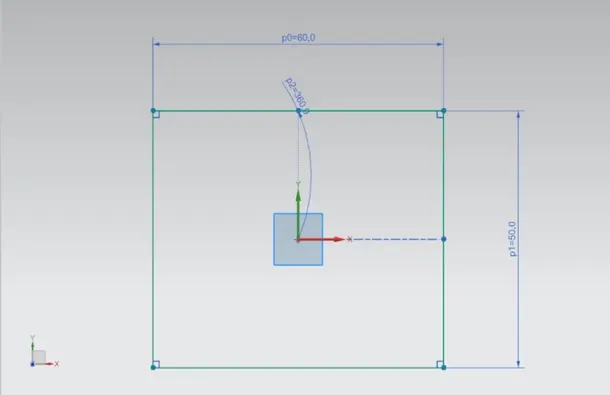
Tab: Tab feature is used to create a base feature by extruding a sketch along a vector by a thickness value, or adds material to a planar face.
Step 2: select the tab in menu → select the base, select the curve, and enter the material thickness value.
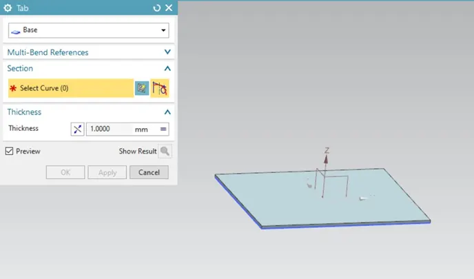
Tab
Normal Cutout: Normal cutout, cut material by projecting a sketch onto the model and then cutting perpendicular to the faces intersected by the projection.
Step 4: select the top face of the sheet metal for a rectangular sketch as per the given dimensions → Select the Normal cutout, select the curve, body and required depth in respective direction.
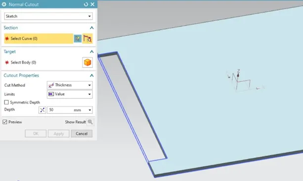
Normal Cutout
Bend: This feature is used to modify the model by bending the metal sheet on one side of a sketch, such as line, adding a bend between the two sides is also possible.
Step 5: Draw a line on the surface of the sheet → select the bend feature from the home tab: bend gallery → bend.
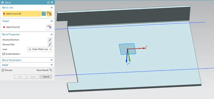
Bend
Flange: The flange is a feature that adds a flat flange at a required angle to a planar face and adds a bend between the two.
Contour Flange: The contour flange is used to create a flat flange by extruding a sketch along a vector or sweeping a sketch along an edge or chain of edges.
Step 6: Select the flange feature → select the edges → enter the dimensions of the flange such as length, angle, length reference, Inset, and bend parameters.
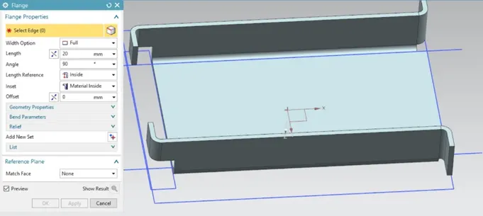
Contour flange
Break Corner: Break corner feature is used to round or chamfer a sharp corner of a tab or flange.
Step 7: Break corner feature is select to blend the sharp corners of the model with radius of 10 mm.
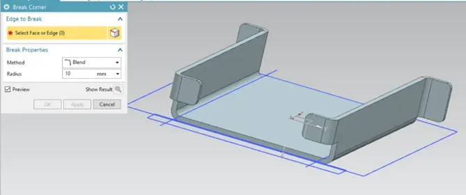
Break corner
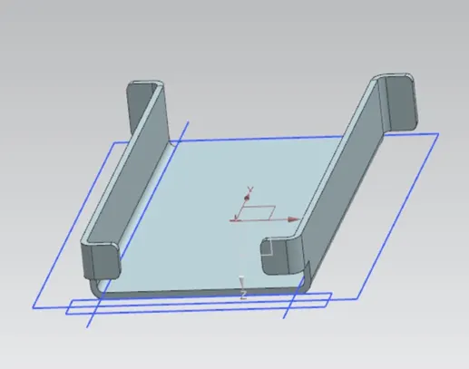
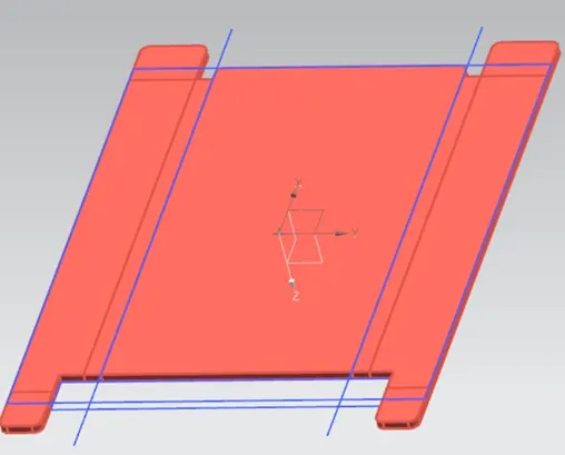
Step 8: Before adding a punching feature or the stiffness feature to the model. We should first use unbend feature to a flat plate. Select the bend faces to unbend.
Unbend: The unbend feature is used to flatten a bend and the material adjacent to the bend.
Unbend
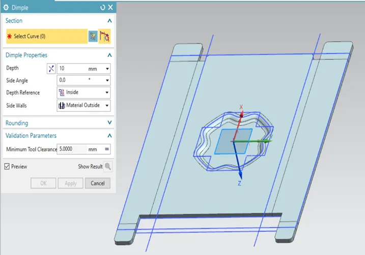
Dimple: The dimple feature punches material from a model based on the profile of a sketch to a specified Depth. This feature provides more strength and rigidity to the flat structure of the component.
Step 9: Draw the sketch as per given dimensions → select the dimple → select the profile, enter the depth and other parameters as per requirements.
Dimple
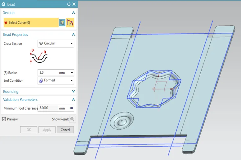
Bead: The bead feature is used to lift material along the contour of a sketch that simulates a stamping tool.
Step 10: Select the bead feature under punch feature on home tab → Create the sketch → select the Cross-section type required and radius. Use the mirror feature to replicate the bead to the four corners of the sheet.
Bead
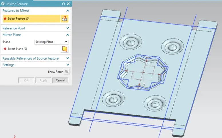
Mirror
To apply the holes to the metal sheet, unbend the part. While selecting the location and the diameter of the hole, should follow the general guidelines of the holes.
Step 11: Select the hole from the menu tab → Select type of the hole, need for the purpose → Select the sketch, direction to the hole → entering the diameter and depth of the hole → Apply the feature.
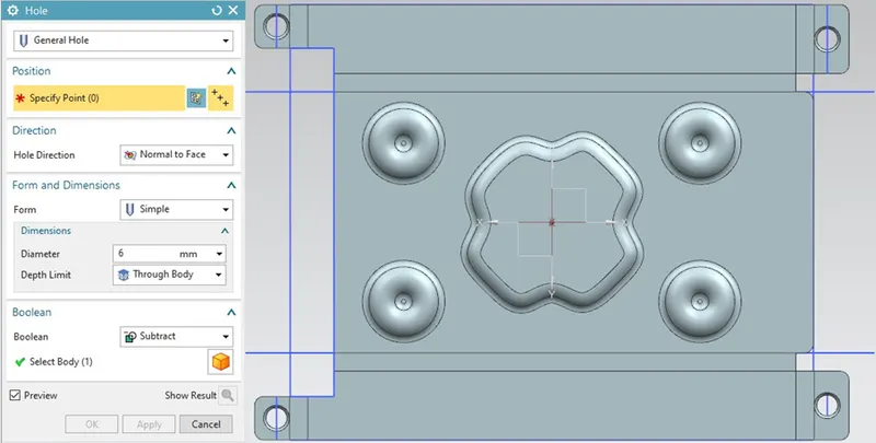
Hole
Rebend: This feature is used to restores an unbend feature to its previous bent state, along with any features added after the unbend feature.
Step 12: After applying for the all the features required for the design of the product. To review final design shape of the product, looks like after manufacture.
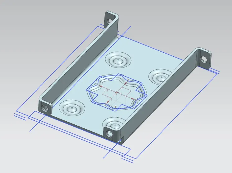
Rebend
Flat Pattern: Creates a flat pattern feature from the formed sheet metal part. It gives a detail information about the bend radius, bend angle, bend direction and bend sequence steps which help in the manufacturing process.
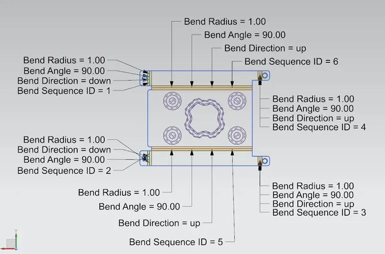
Flat Pattern
- Different Views of the Sheet model:
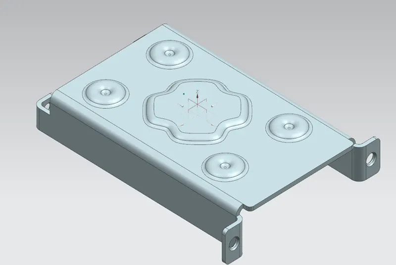
Isometric view.
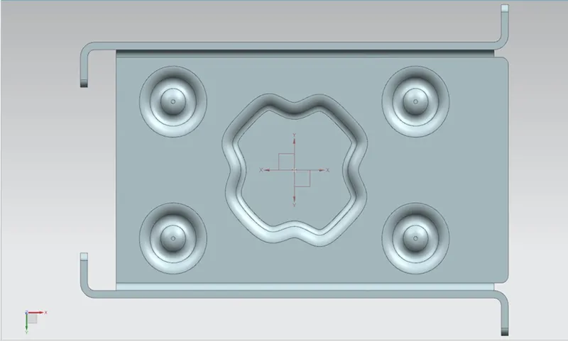
Bottom view
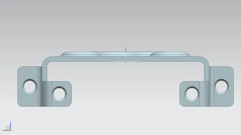
Front view
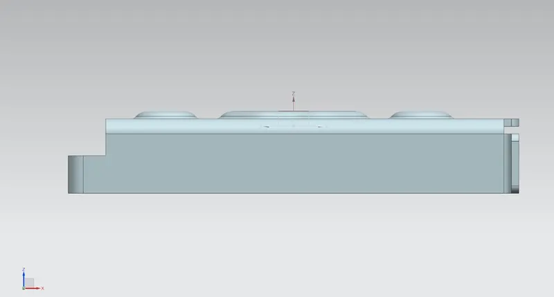
Side View
- Drawing of a Sheet Metal:
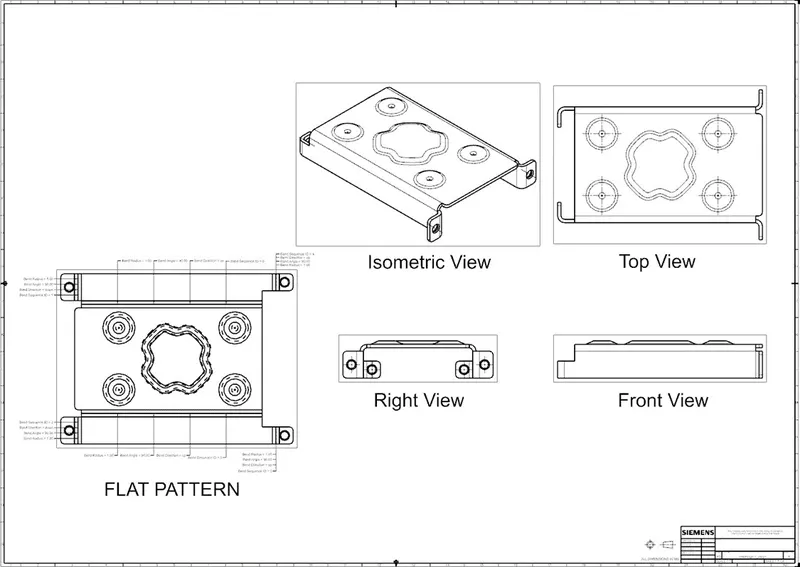
Drawing Sheet.
- Conclusion:
The sheet metal design was created as per the given dimensions and features such as bend, flange dimple mirror etc. are used in the process of design the sheet metal.