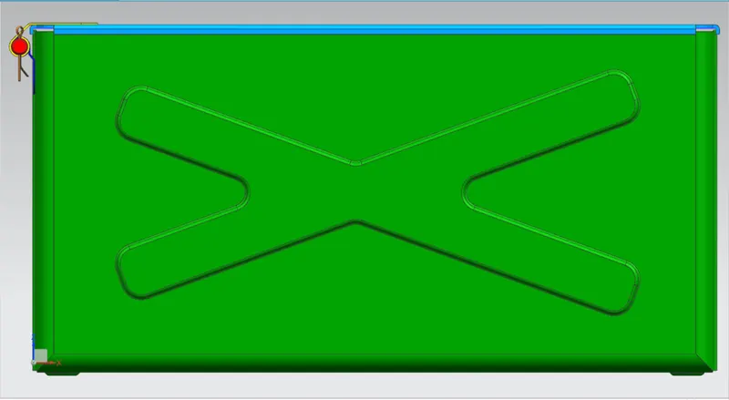
Advanced Sheet Metal Design Using NX Cad Challenge_2_Box Assembly
Designing an Enclosure Box Assembly Using Advanced Sheet Metal NX CAD.
- Objective:
Designing a sheet metal box with a lid in Siemen NX CAD by using advanced features such as ‘Hem flange’, ‘Closed corner’, ‘Dimple’, ‘unbend’, ‘Bead’, ‘Normal cut-out’ etc.
2. Introduction:
Sheet Metal Fabrication is the process of forming parts from a metal sheet by punching, cutting, stamping, bending, etc. sheet metal parts are known for their durability, which makes them great in the application of making chassis, PC cases, enclosure boxes. Another advantage of sheet metal fabrication is more cost-effective for both low volume prototypes, and high-volume production runs. Because of all the above advantages of sheet metal, it is used in industrial fields such as Machinery, Automotive, Aerospace, Packing, etc.
3.Design methodology:
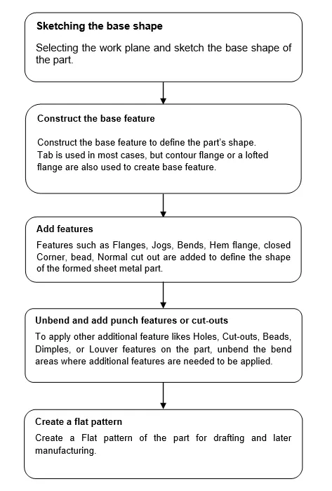
4. Description of Features and procedure of designing enclosure Box:
Step 1: Open the Siemens NX → select the file from the menu → to select the new file or use the shortcut CTRL + N → select the sheet metal as file type → save the file with the project name and in the desired folder → Select the menu, preferences, sheet metal, and set user requirements as default
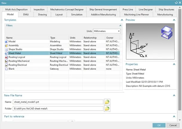
Opening New File.
Step 2: Select the datum CSYS → Select the sketch icon in the menu, Orient the plane → Draw the sketch according to the given dimensions.
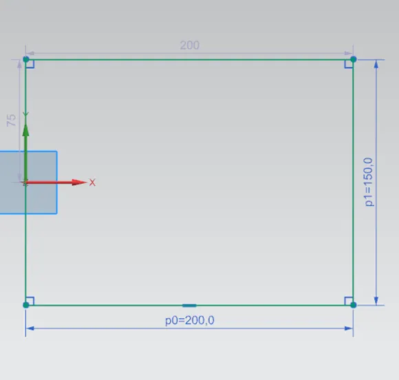
Base sketch
Step 3: Select the tab in the menu → select the base, select the curve, and enter the material thickness value (1mm).
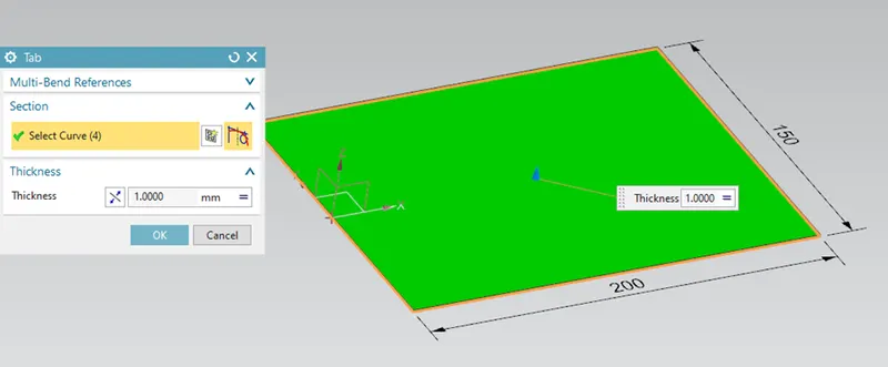 Tab.
Tab.
Step 4: Select the flange feature in the menu → Select the respective edges → enter the dimensions of the flange such as length, angle, Length reference, offset, and bend parameter.
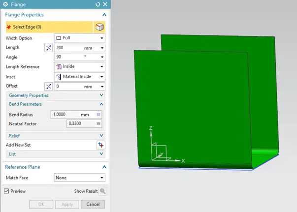
Flange 1
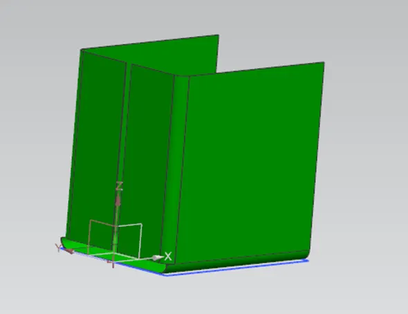
Flange 2
Step 5: Select the closed corner feature to extend and close the gaps formed by flanges → select the adjacent edges of the flange → Select the corner properties such as treatment, overlap, Gap → Select the ‘Apply’.
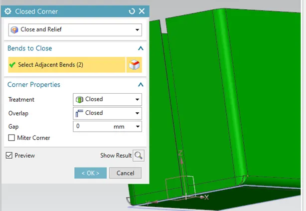
Closed Corner.
Step 6: To close the open gap on the sidewall of the box by using a grooved seam joint.
Grooved seam joint: It is one of the sheet metal fabrication techniques used for self-locking joints of cylindrical or conical shape objects.
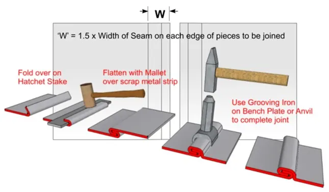 Steps involved in Making the Grooved seam joint.
Select the flange feature → select the adjacent edge → enter flange properties and repeat it to create the below feature.
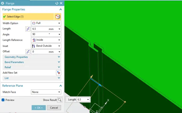
Grooved seam joint.
Select the Hem feature to finish the Grooved seam joint, Select the open type of flange → Select the edge → select the inset options (bend outside) → select the bend parameters.
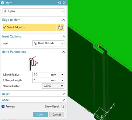
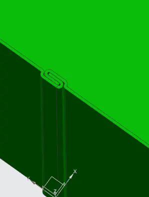
Step 1 and step 2 to finish the grooved seam joint.
Step 7: select the mirror feature and create the other half of the box, to form a complete container shape. Select the untie feature, to create a single sheet body.
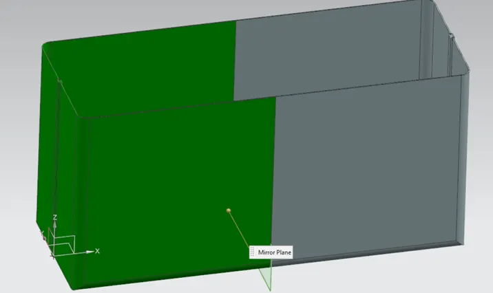
Mirror feature.
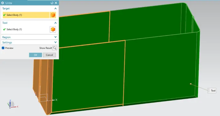
Unite Feature.
Step 8: Select the sketch → select the outer surface large side of the box and draw the desired shape of the dimple → select the Dimple feature → to select the curve → to enter all respective values according to requirements and select the ‘side wall’ to ‘material Outside’.
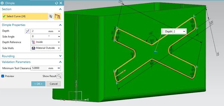
Dimple feature.
Select the above dimple feature and mirror it to the opposite sidewall of the box.
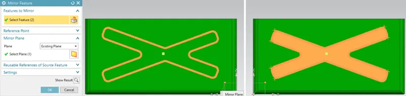
The first image is the mirrored feature and the second image is the selected dimple feature.
Select the sketch to create the shape of the dimple on the outer side of the base of the box → Select the dimple feature and enter all the required parameters (note: select the direction of depth into the box).
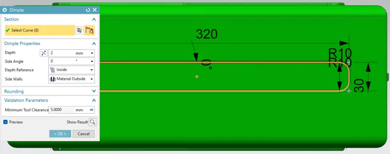
Dimple on the base of the box.
Step 9: Before moving to the process of creating a lid of the box, to check the production compatibility of the open container, Use the feature of unbend and Rebend.
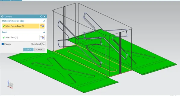
Unbend.
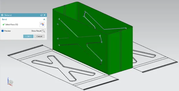
Rebend.
Step 10: create of bead, select the outer side of the base → create the sketch of the circle → select the bead feature → to select the curve, depth (outwards), radius and end condition → Select the mirror feature to duplicate the bead to all four corners of the base.
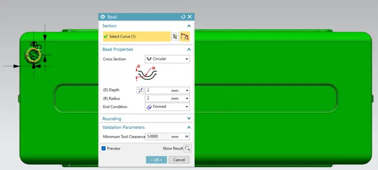
Bead.
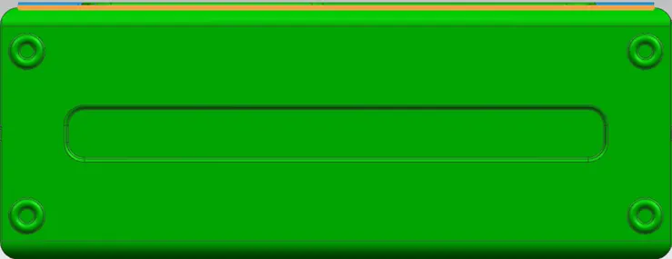
Bead to the four corners using the Mirror feature.
Step 11: select the hem flange feature → select the top edges of all four sides of the container to provide a smooth edge and stiffness.
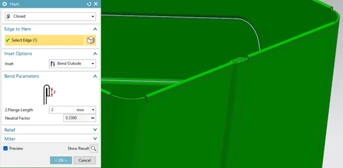
Hem flange.
Design of the Lid and Hinge support:
Step 12: Select the Tab feature → to create the lid from the sketch → select the flange feature → select the edges of the newly created lid and created it as shown in the below figure.
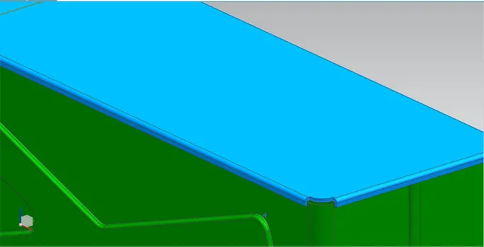
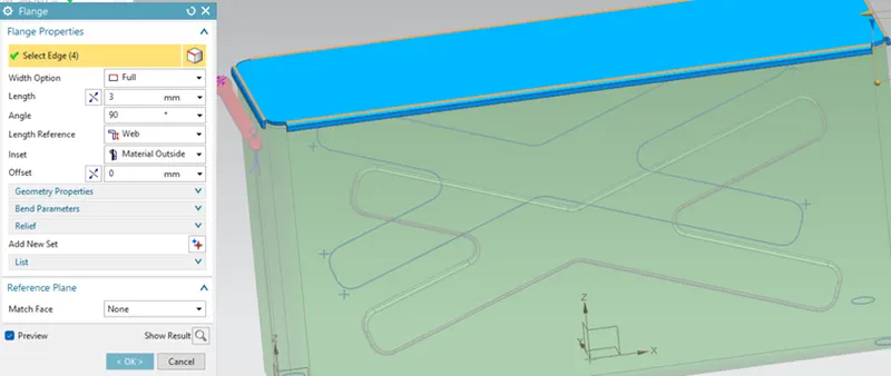
Box lid with flange.
Step 13: Creation of the hinge joint → create a tab on the side face of the container, as shown in the below figure using the tab feature. To create, draw the sketch as per the given dimensions.
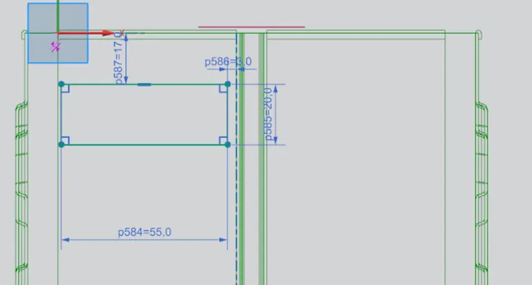
Hinge joint sketch.
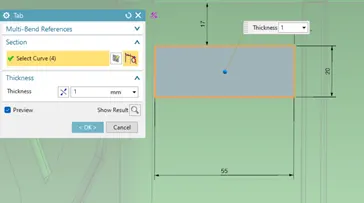
Step 14: Select the tab feature → select the curve and enter the thickness of the sheet as 1mm → apply the break corner feature, select the corner shown in the below figure and bend radius of 10mm.
- a)
 b)
b)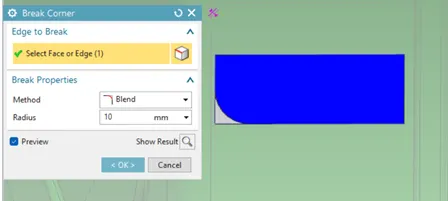
- a) Tab feature and b) Break corner.
Step 15: To create the hinge shape, create a flange as shown in the below figure and given dimensions. Select the hem flange feature to design the open loop as per the given dimensions.
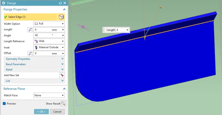
Flange feature 1.
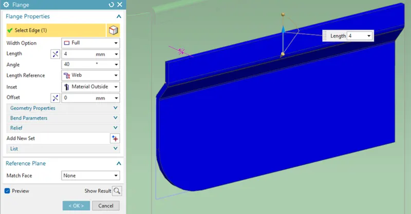
Flange feature 2.
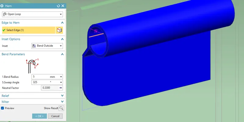
Hem flange with open loop.
Step 16: To create cut out through the loop, first unbend the loop → create the sketch on the surface of the flatten loop → apply the normal cutout feature, select the sketch, and cut depth of 5mm → apply the Rebend feature.
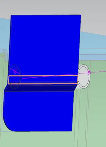
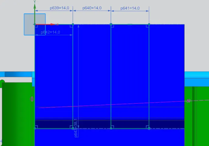
Unbend, sketching of cutting slots
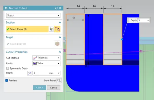
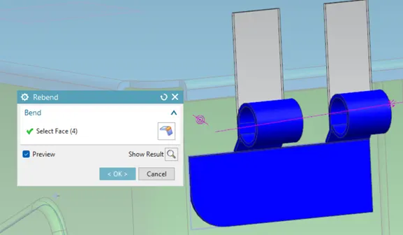
Normal Cut out; Rebend
Step 17: Create the mirror of the open loop of the hinge joint.
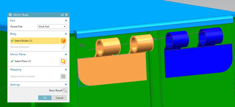
Mirroring
Step 18: To create another side of the hinge joint, repeat the above steps according to the given requirements on the top side of the lid as shown in the below figure.
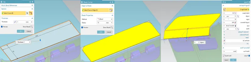
The sequence of features used in order are Tab → Break corner → Flange
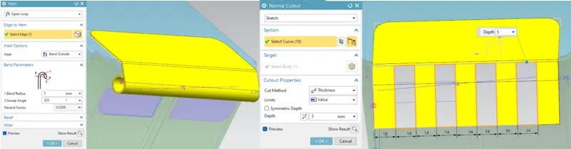
Hem → Unbend → Normal cutout
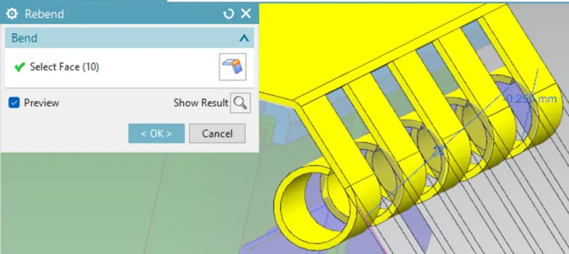
Rebend.
To complete the assembly of the box a cotter pin bolt and cotter pin are designed and assembled.
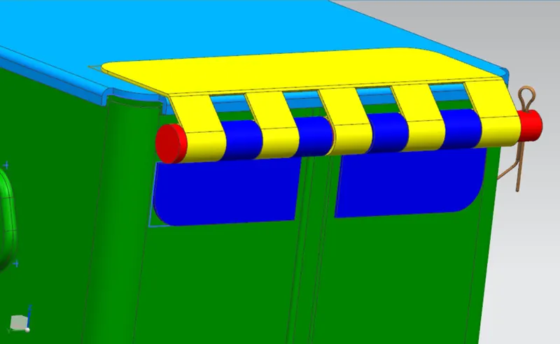
Cotter bolt and pin
Conclusion: The objective of designing a Box assembly has been achieved by using different features and tools, that are available in the Siemen NX sheet metal.
Views:
Isometric view:
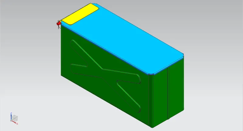
Left Side view:
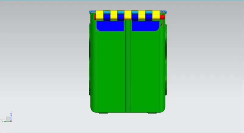
Top view:
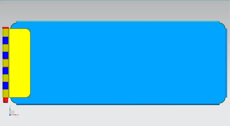
Front View: