Advanced Sheet Metal Design Using NX Cad Challenge_5_Odd Shaped Enclosure
Designing of an Odd Shaped Enclosure Using NX Cad
- Objective: The Designing of an odd Shaped sheet metal parts using Siemens NX Sheet Metal. The main objectives of this project are conversation a solid body into a sheet metal part, and add odd shapes to the part by using features and tools available in the NX Sheet metal application to achieve desired shape and size of the enclosure.
- Introduction:
Sheet Metal Fabrication is the process of forming parts from a metal sheet by punching, cutting, stamping, bending, etc. sheet metal parts are known for their durability, which makes them great in the application of making chassis, PC cases, enclosure boxes. Another advantage of sheet metal fabrication is more cost-effective for both low volume prototypes, and high-volume production runs. Because of all the above advantages, sheet metal is used in industrial fields such as Machinery, Automotive, Aerospace, Packing, etc.
- Design methodology:
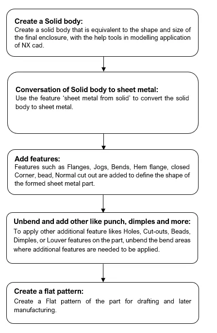
- Description of Features and procedure for designing odd shape enclosure:
Step 1: Select the Modeling → select the work plane → create a sketch and apply to extrude feature to create a solid body.
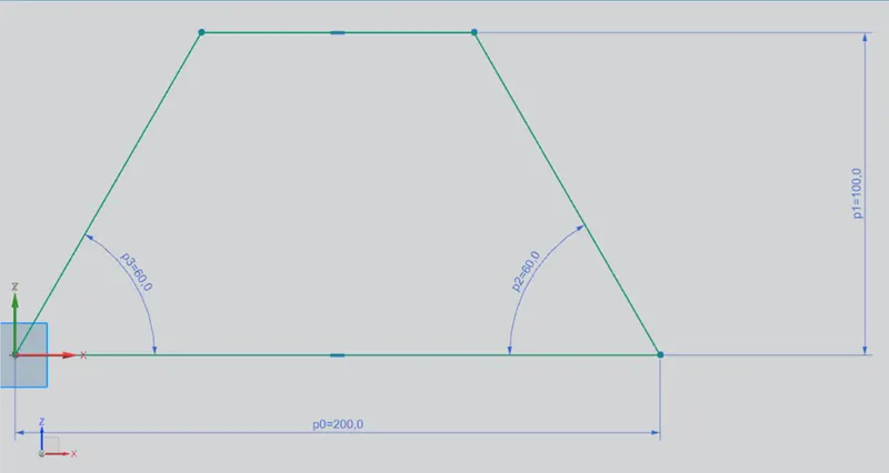
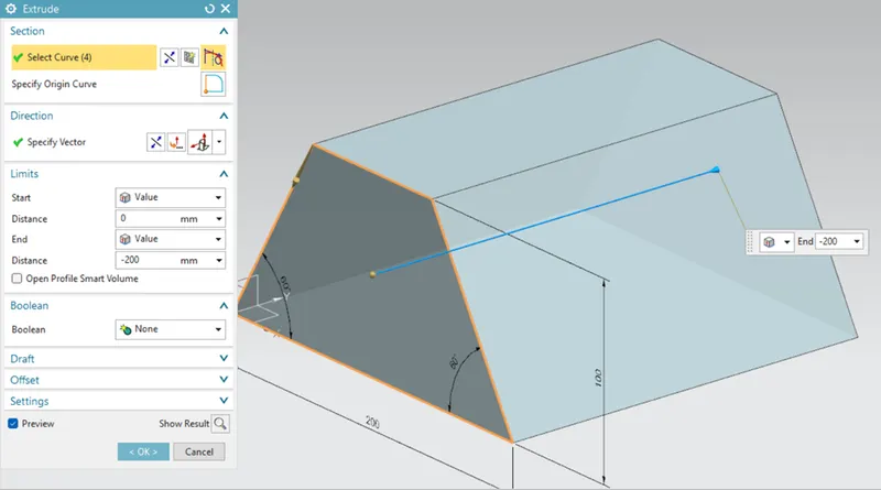
Extrude.
Step 2: Select the feature ‘Sheet metal from solid’ → Select the face and Thickness of 3mm → Select the edge and Bend radius of 3mm.
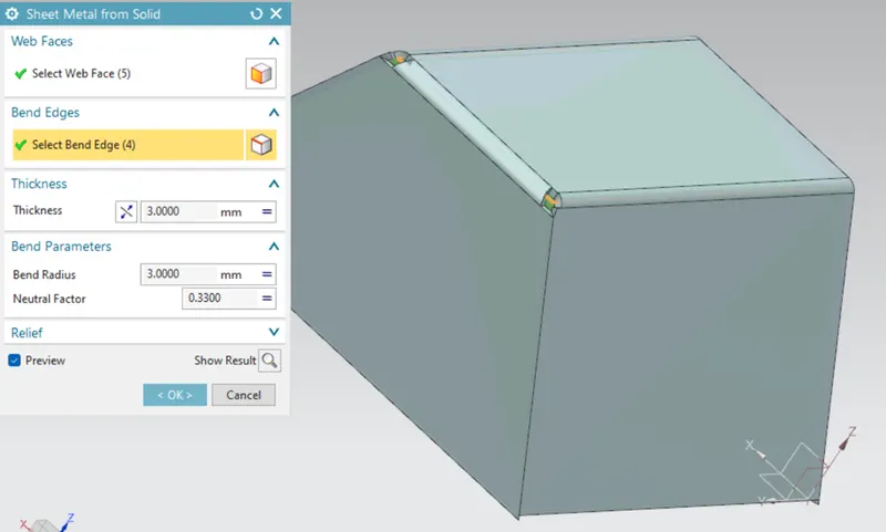
Sheet metal from solid.
Step 3: Select the flange feature → Select the edge as shown in the below figure, length 20mm, and angle 90.
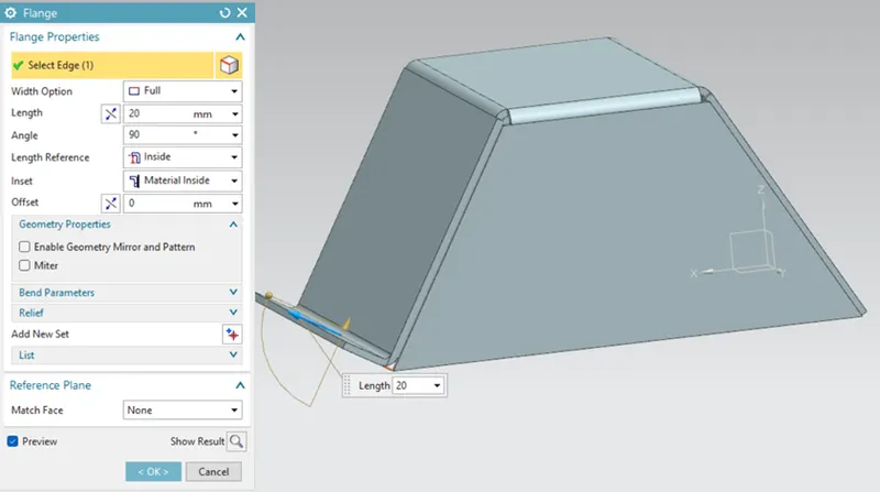
Flange.
Step 4: To apply the jog feature → sketch a line on the left side of the enclosure → Apply the jog and given dimensions.
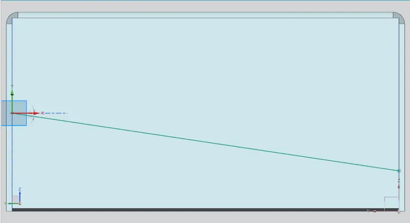
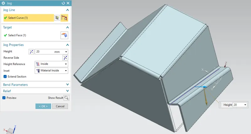 Jog.
Jog.
Step 5: To add more features, unbend the enclosure → Select the Stationary face and edges → Select the bend faces to unbend.
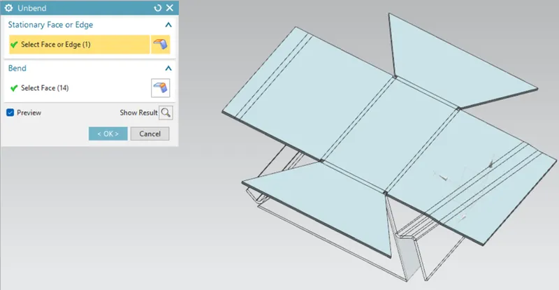
Unbend.
Step 6: To add the bead → Sketch the lines on the bottom face of the enclosure → apply the bead to the sketch as per the given dimensions.
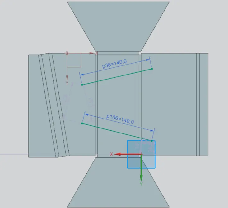
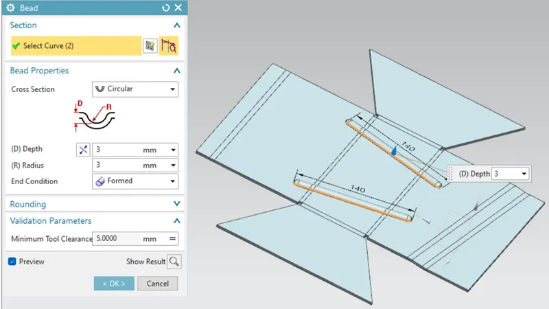
Bead.
Step 10: To create holes → select the hole tool → to select the typed of hole required to → select the specified point on the surface of the unbend sheet → specify the required dimensions.
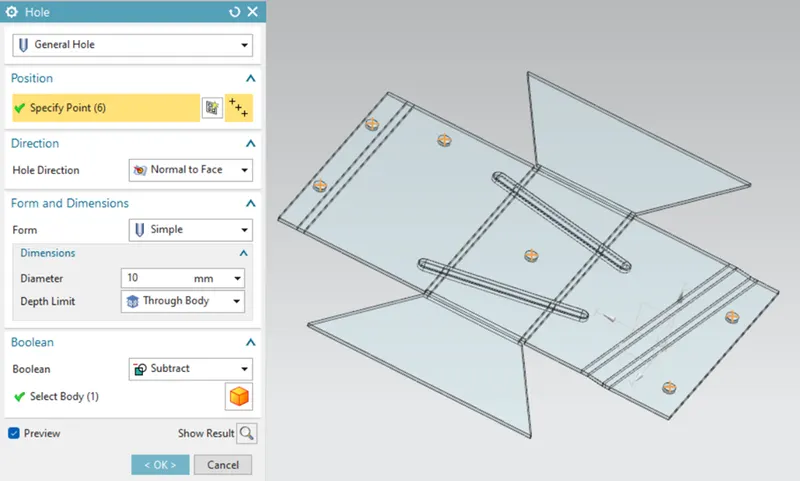
Holes.
Step 11: Apply Rebend feature to finish and to have an overlook the final design of the product. Select all the faces required to be bend in an order.
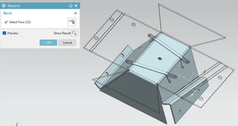 Rebend.
Step 12: Flat pattern: The shape of the sheet metal part before it is formed, to create drawings for manufacturing. Flat patterns show bend lines, bend zones, punch locations, and the shape of the entire part with all bends flattened and bend factors considered.
Select the flat pattern tool → Select the face and edge.
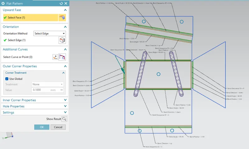 Flat Pattern.
Step 13: To create the drawing sheet → open the file → Create New drafting → Select the size A0 and select ‘Base View’ → Select the Flat Pattern and scale 2:1.
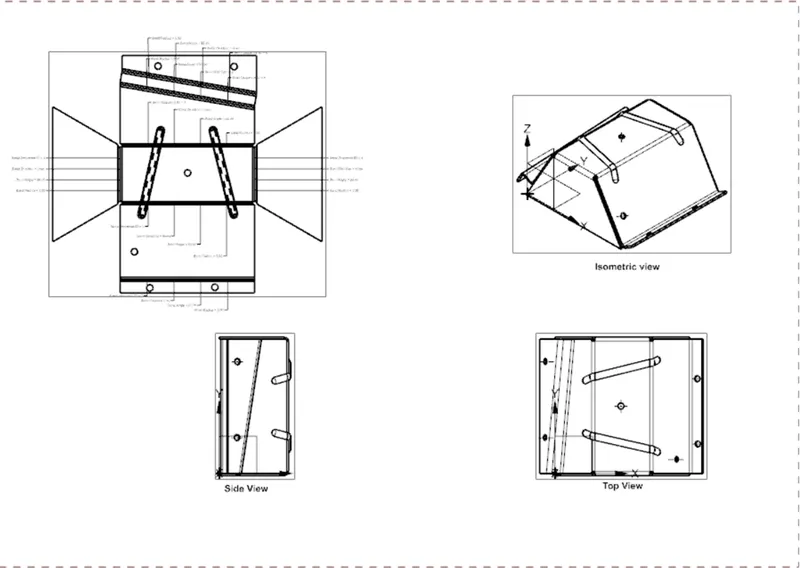
Drawing.
Conclusion: The design of odd shape enclosure along with the Flat pattern was achieved by using the above sequences of steps from the solid body to sheet metal.
View:
Isometric View:
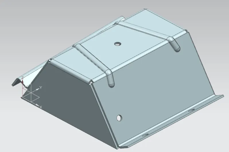
Isometric View.
Side View:
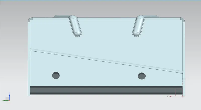
Side View.
Front View:
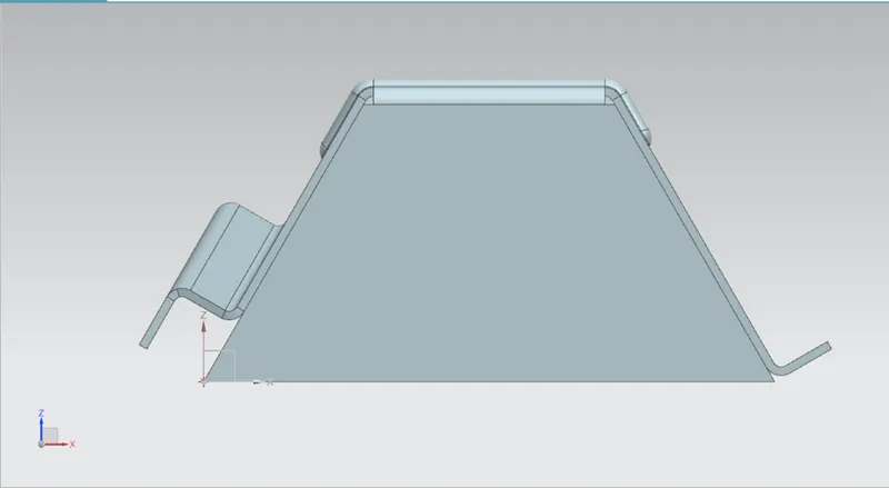
Front View.
Top View:
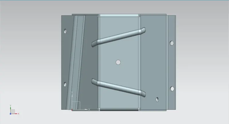
Top View.