Radar Mast & Final Assembly of Yacht
Designing of a Luxury Yacht.
Objective: Designing of a Yacht as per the given dimensions and the blueprint by using Solid Works 2020. Rendering the yacht in photo view 360 tool.
1. Introduction: Yacht is a luxury sailing or power vessel used for the recreation, cruising, and various vacation activities. Typical yachts are designed to provide comfort, aesthetic quality looks. The good streamline design properties to optimizes between speed and comfort.
The designing and construction of the super yachts and huge cruises are done Block construction method.
Block construction is a modern shipbuilding method which involves the assembly of prefabricated modular sections. Cross-section of the yacht is dividing into individual sections and assembling them to form the final design. In this designing practices, the yacht is divided into following individual parts.
- Propeller.
- Radar.
- Hull.
- Front Seat.
- Middle Seat.
- Rear Seat.
- Superstructure.
- Radar mast.
Design Methodology: -
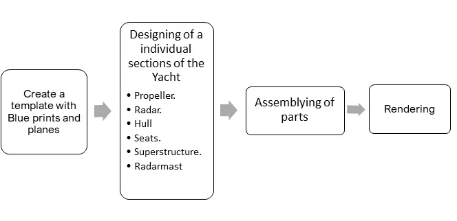
Workflow Flow Chart.
1.1. Design of Propeller:
A propeller is a device with a rotating hub and radiating blades that are set at a pitch to form a helical spiral, that, when rotated, exerts linear thrust required by the yacht to move through water. The helical spiral shape of the propeller creates a pressure difference between the two surfaces of the blades. The following feature are used to create the propeller.
- Revolver.
- Loft.
- Circular patten.
- Cut-Extrude.
- Fillet.
Revolve: The revolve is a feature used to add or remove material by revolving one or more profiles around a centreline. The revolve feature can be used to create a solid, a thin feature, or a surface.
To create a revolve feature following sequence of steps need to be followed:
- Create sketch profile of cross-section of the hub of a given dimensions.
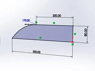
- Select the centreline or axis of which the part revolves to create boss solid or cut extrude.
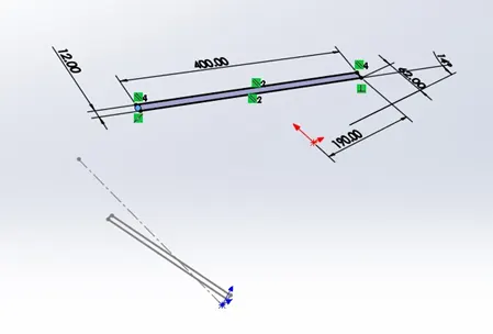
Loft: loft is the feature used to create the transitions between two or more profiles. A loft can create a boss, cut, or surface. All sketch entities, including guide curves and profiles, can be contained in a single 3D sketch.
- Insert > Boss/Base > Loft > select the profiles > select the guide curve.
- Loft feature is used to create the blades of the propeller.
- Create a rectangle profile on the top plane and create other rectangle profile on the plane parallel to top plane.
- Select the two profiles and the guide curve to form a solid and merge result with the hub.
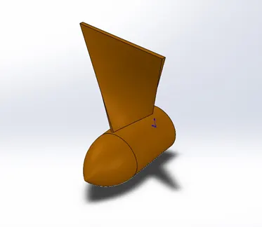
Fillet: Fillet feature is used to create a rounded internal or external face on the part. There are different types of fillets for etc., constant size fillet, multiple radius fillet, setback fillet, variable size fillet, face fillet, full round fillet, and Asymmetric fillet.
The steps to apply fillet:
- Insert > Features > Fillet/Round > select the edges > select the fillet parameter to symmetric > apply fillet radius.
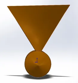
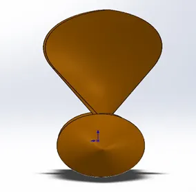
Cut-Extrude: It is a sub- feature of the extrude. The extrude is used to convert the closed profile into boss, surface and cut. This feature is used to remove or cut material from a part or an assembly.
- Insert > Cut > Extrude > selected the profile > enter the required depth.
- Draw a circular profile on the flat surface of the hub and apply cut-extrude feature.
- Select the profile and cut-extrude in the direction of hub.
- This hole is used to mount the propeller on to the end of the driving shaft of the Yacht.
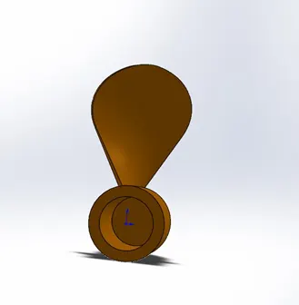
Pattern: Pattern repeats the selected features in an array based on a seed feature. The pattern is sub-divided into 1) linear pattern, 2) circular pattern, 3) curve driven pattern, and sketch driven pattern or table-driven pattern.
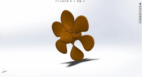
CirPattern: Here circular pattern is used to create multiple instances of one or more features, space uniformly around an axis or circular profile.
The steps to apply circular pattern:
- Insert > Pattern/Mirror > Circular Pattern > Select the features to be duplicate > Select the edge (equal spacing) > number of instances.
1.2. Design of Radar:
The radar is the eyes of the yacht, and it is also used navigate the position in the real time. The marine radars are using X band or S band frequencies, used to detect other ships and land obstacles, to provide bearing and distance for collision avoidance and navigation at sea. The radar is on the highest position on the yacht to scan far objects and sits on the rotating platform to cover 360-degree view. The feature and steps are used to create the radar:
- Boss-Extrude.
- Fillet.
- Cut-extrude.
- Sketch-pattern.
- Combine.
- Mirror.
- Split line.
Combine: Combine is used to add, subtract and common the multiple solid bodies to create a single-bodied part or another multibody part. Combine bodies feature can only apply to the multibody part file.
Insert > Features > Combine.
The following are the sub-feature in the combine.
ADD: The add is used to combines solids of all selected bodies to create single body.
Subtract: The subtract is used to removes overlapping material from a selected main body.
Common: The common is used to removes all material except that which is overlaps between the selected multibody.
Split lines: The split line tool projects an entity (sketch, solid, surface, face, plane, or surface spline) to surfaces, or curved or planar faces. It divides a selected face into multiple separate faces.
Insert > Curve > Split Line.
- Projection: projects a sketch on a surface. Split lines and sketched text used to create decals on the surfaces.
- Silhouette: This option in spilt line is used to create a split line on a cylindrical part.
- Intersection: Split faces with an intersecting solid, surface, face, plane, or surface spline.
The following are the step involved in create the radar:
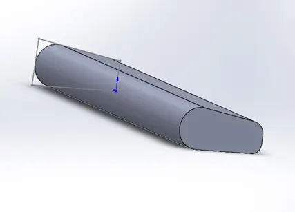
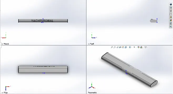
1) By taking advantage of the symmetric of radar about middle plane. The basic profile of the radar is draw on the midplane and the extrude feature is used.
2) The fillet applied to the edges of the extruded solid as show in the figure below.
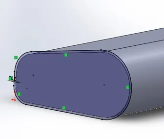
3) To create fixing plate at the end of the radar, select the outer surface of the extrude to sketch, offset the edge and boss extrude the profile.
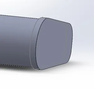
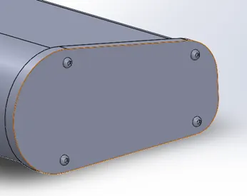
4) The four rivets are created around the four corners by using boss extrude, cut-extrude, fillet and Sketch-pattern.
5) The combine feature(add) is used to make into single body from the above created multibody and mirror the body about the reference plane(mid-plane).
6) A slot is created on the bottom face of the radar and to mount the radar onto the radar mast.
7) The split line feature and text option in the sketch are used to create name of the yacht (decals), and projected lines to the front face of the radar.
1.3. Hull:
The hull is the watertight body of a yacht or a ship. It provides a base platform on which other block sections of the yacht such as superstructure, seats, radar mast etc, to assembly. The line where the hull meets the water surface is called waterline. The design of hull needs good knowledge and skills over various surface feature and curves.
The following set of feature and steps are used:
- Surface Loft.
- Surface Trim.
- Surface Extrude.
- Surface Knit.
- Surface Fill.
- Shell.
- Surface Extend.
- Fillet/ chamfer.
- Sweep.
- Revolve.
- Dome.
- Helix/spiral.
- Linear-Pattern.
- Split
- Delete Face.
- Combine.
- Mirror.
Feature:
Surface Loft: Loft surfaces are surfaces generated by multiple 3D Curves or existing edges creating a smooth tangency between the selected curves.
Insert > Surface > Loft.
Surface Trim: Surface trim tool is used to trim the intersecting surfaces and can also use remove the conjunction surface with additional surfaces.
Insert > Surface > Trim.
The types of the trim:
- Standard: Trims surfaces using surfaces, sketch entities, curves, planes, and so on.
- Mutual: Trims multiples surfaces using the surfaces themselves.
Extruded-Surface: The extrude-surface feature is used to create a 3D faces from the plane, edge, 2D face or sketch line and define the direction of extrusion.
Insert > Surface > Extrude.
Knit surface: The knit surface tool is used to join or combine two or more faces and surfaces into single surface. The closing volume of knit surfaces can form solid from the surfaces or leave as a surface body.
Insert > Surface > Knit.
Extend Surface: The extend surface tool is used extend tangent surface by selecting an edge, multiple edges, propagate or a face.
Insert > Surface > Extend.
The following are the extension types:
- Same surface: Extends the surface along the geometry of the surface.
- Linear: Extends the surface tangent to the original surface along the edges.
Surface Fill: surface fill feature is used to constructs a surface patch with any number of sides, within a boundary defined by existing model edges, sketches, or curves, including composite curves.
Insert > Surface > Fill.
Shell: The shell tool hollows out a solid part. By using this tool, it can create both hollow solid with open face and a closed hollow model. Multiple thickness is also possible in shell.
Insert > Features > Shell.
Sweeps: Sweep creates a base, boss, cut, or surface by moving a profile (section) along a path.
The following are steps involved in the design of the hull.
Import the blueprint of the yacht in different views into the part file and create two new planes i.e., back plane, top plane parallel to front plane, bottom plane respectively.
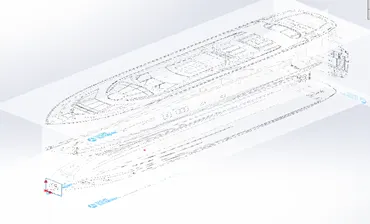
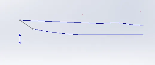
- Create a two individual sketches, one on middle plane and other on bottom plane with the reference of blueprints. Use projected curve feature to create 3D curves (curve1) and repeat the same procedure to create other 3D curves (curve 2).
- We are using various surface feature in throughout the design of the hull because of more complex shape of the hull. Surface-loft feature is used to create the surface loft 1 between the curve 1 and curve 2, and the guidelines.
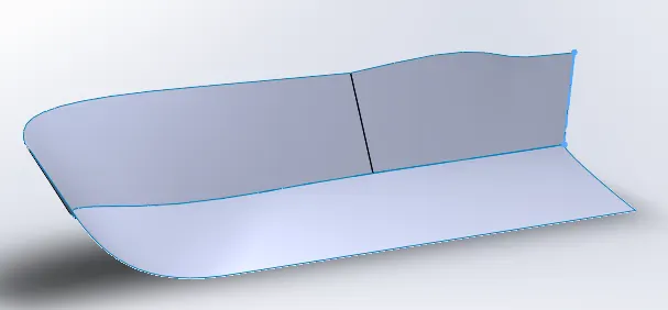
- Trim the extra surface by trimming tool and following the sequence of operation to create basic solid shape of the hull.
Sketch the curves > apply Surface Loft/ trim/ extrude/ Knit/ Fill > Create solid.
5. Apply shell feature as show in the below figure.
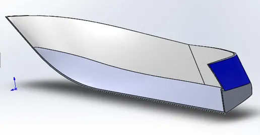
6. A solid base is created in the shell hull by drawing a sketch on mid-plane by convert entities of the edge of the shell and trim tools as show in the below figure.
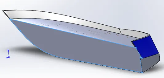
- The following sequence of features are used to create below.
- Cut extrude the wall on the back side of the yacht, create the sketch on the mid-plane and enter the required depth.
- Boss-extrude the support platform on the back side of the yacht, create the sketch on the mid-plane and extrude to required depth, and select merge results. The fillet and chamfer are applied to the required edges.
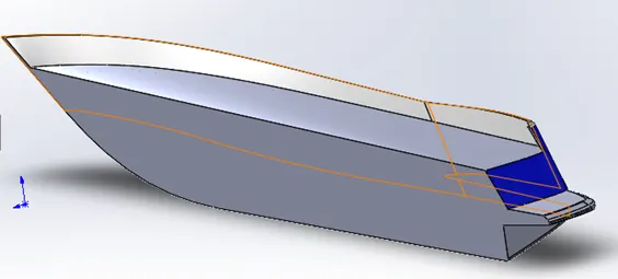
- The windows for the lower deck on the yacht are designed by the below sequence of steps.
- Additional plane is created parallel to the mid plane and required sketches are created on the new plane1 and cut-extrude feature is used to create cut on the outside of the hull.
- Cut-extrude > select the sketch > direction 1 (offset from surface) > select the face of offset.
- The above sequence of steps is repeated to create other slots.
- The fillets are applied to the corners.
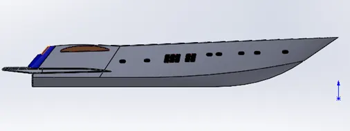
- Watertight gaskets are created around window by using sweeping feature.
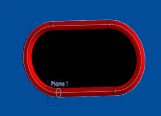
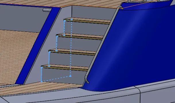
- Creation of steps on the back of the hull, at first sketch is created on the top plane and cut extrude up to the surface. The step sketch is draw on the side plane of the steps and boss extrude the profile up to next surface.
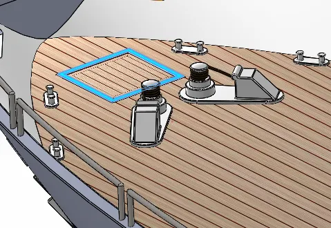
- Creation of Hatch door, create a square profile on the top surface of the deck and boss extrude the profile. Apply fillets to the edges of the extrude.
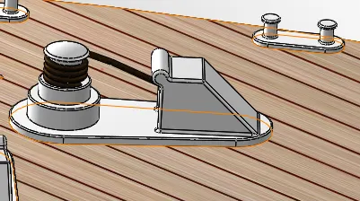
- Creation of Yacht Anchoring system, the anchoring system consist of cable lifter, Anchor lashing, rope, and Anchor. To create the cable lifter and anchor lashing, the following sequence of steps are followed.
- Sketch the profile > boss extrude the platform > create a plane 12 > draw a step profile on the plane 12 > revolve feature is used > chamfer and dome feature are used for finishing > A new Plane 13 is created in the mid of the boss extrude > the hawse pipe profile is draw on the plane 13 > boss extrude (direction 1 mid-plane and distance 200 mm) > create the profile on the front face of the hawse pipe > cut-extrude ( direction1 blind and depth 180mm) > Create a rope around the cable lifter to hold the anchor > Helix/spiral around the top step of the cable lifter > a plane 14 is created at starting of the helix curve and a circle is drawn on the plane > apply the sweep feature.
- The Designing of an Anchor, it is symmetry about centre line. So, we are creating half section and using mirror option to finish the design.
- Draw a profile on the mid plane and boss extrude (offset from surface), select the face.
- Create a plane 26 and plane 27 and, draw a sketch on the plane 27 and boss extrude the profile.
- Drawing different sections of the anchor as per given dimensions and boss extrude all the profile respectively.
- Chamfer and fillet are applied to the edges and mirroring all the feature of the anchor about the centre line and check the box of the merge result in green.
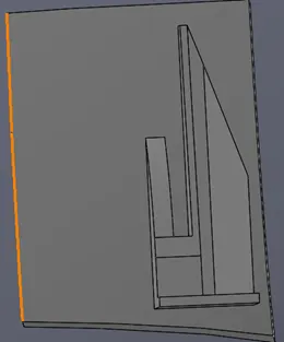
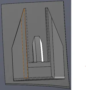
16. Designing of garage,
- Draw a sketch on the mid plane and cut-extrude and apply thin feature into the direction hull.
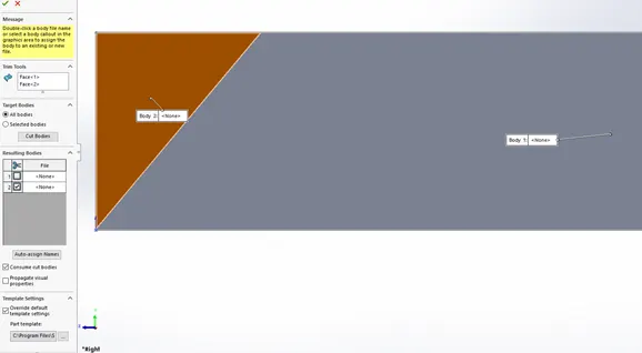
- Use split tool to save the cut-extrude part for the design of the garage door.
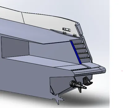
The pins to hold the garage door are boss extruded in the location as shown in the figure below.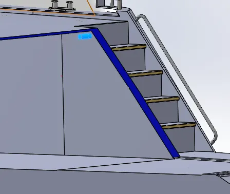
17. Creating of DECK Surface, apply offset surface feature select the top surface of the deck and save the surface as DECK SURFACE for further use as a base to design the superstructure.
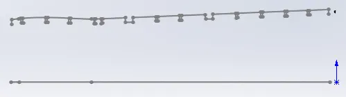
18. Design of Side rails, To create 3D curve the below steps are followed:
- Offset entities of the outer edge of the side wall on to the bottom plane.
- Offset entities of the outer edge of the side wall on to the mid-plane and repeat it again with 300mm offset distance
- Use the sideview of the blueprint as a reference and join the two parallel offsets with line segments.
- Add the given dimensions.
- Trim the extra curve segments and final sketch as shown in below.
- The projected curve feature is used to create 3D curve11 by selecting sketch 131 and sketch 130.
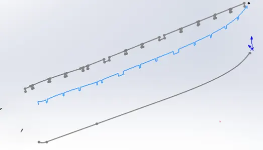
- Create a plane at the starting of curve11 and a circle is drawn on the plane.
- The circle sketch is sweep along the curve11 to create the side rails and fillets are applied to the corners.
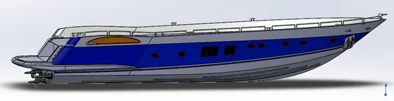
19. Designing of transmission system,
- Draw a sketch on the mid-plane as per given dimensions is shown below.
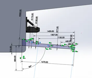
- Revolve the profile around the centre line and, chamfer and fillet are applied.
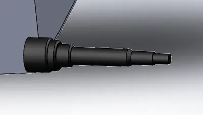
- Rudder shape is drawn on the mid-plane and boss extrude, fillet.
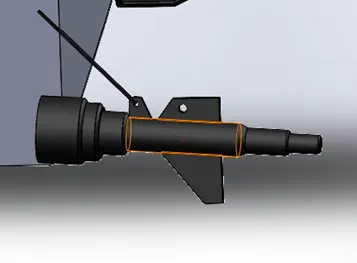
- Draw the pattern direction on the back side of the hull for linear pattern and, all the above features of the transmission are selected and select the pattern direction, number of instances to two, spacing between the two instances to 1600mm.
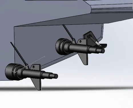
- Create a connecting mechanism to steer all the rudders at once a connect rod is designed. A 3D curve is draw between two centres of the rudder holes and boss extrude is used to create connecting rod.
- Cut-extrude for removing half-section and to use for mirror feature later.
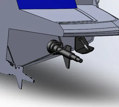
20. To complete the designing of hull, mirror all the feature created above the mid-plane and click on the merge result to create final design of the hull.
21. Add the respective appearances, materials and rendering features in the required areas of the hull to bring the design to more realistic look.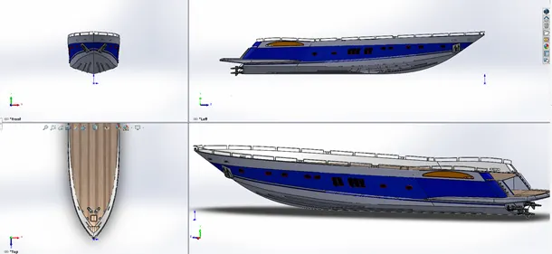
1.4. Garage Door: We designed a solid metal door for the garage of the yacht to protect things that stored in the garage from the ocean waters.
The following sequence of steps and feature are used in creating the garage door:
- The sketch1 with dimension of 6000x1250 mm is drawn on the mid-plane, and boss extrude the profile to a thickness of 1800mm.
- Draw a triangular shape profile on the right face of the above block, and cut extrude thin feature is applied with the sketch (in direction1 Through all and in thin feature with 5mm) as shown in the below figure.
-
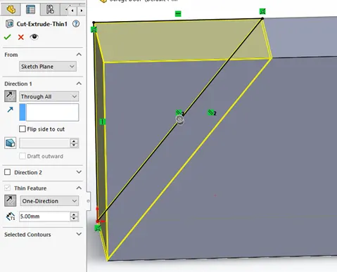
- Split is used to remove cut-extrude part from the design.
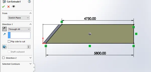
- A quadrilateral shape profile on the right face with given dimensions and cut-extrude (through-all).
- Apply the shell, select the face that need to shell and shell thickness is 100mm and result is shown in below.
- The fillets are applied to all the required edges.
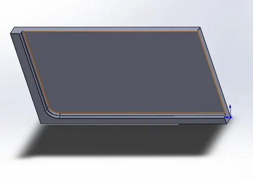
- Cut-extrude the holes to assembly the garage door onto the back of the yacht, fillets applied to required edges and mirror the features and select the reference plane (right plane).
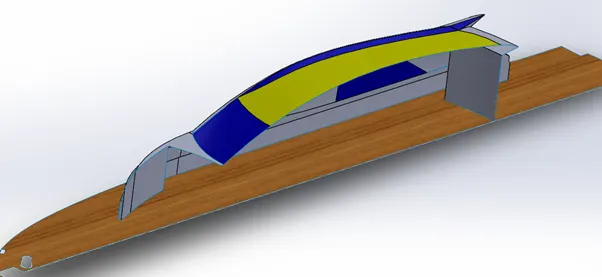
1.5. Superstructure: It is defined as those erections above the freeboard deck which are well within the line of the ship’s side. The main function of the superstructure is to provide protection for the open seas and provide luxury space for relaxing. The design of the superstructure is having more complex surfaces that are hard create by using solid features. The surface design method is used and then convert it into solid.
- The following steps and features are used in creating superstructures:Import the hull into the superstructure part file by selecting insert on the tool bar > select insert part > open document (hull) > select only surface bodies (remove all other transfer).
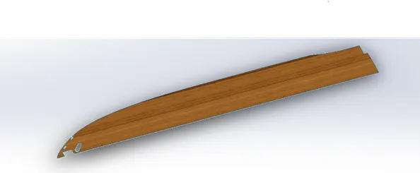
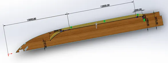
- Draw the sketch using lines and splines on the deck-surface and surface extrude feature and extrude height of 600mm is used as per given dimensions.
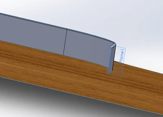
- Create a plane1 at the edge of the extrude surface > draw a line and convert entities of the edge of the surface-extrude > surface sweep > surface-knit > Fillet.
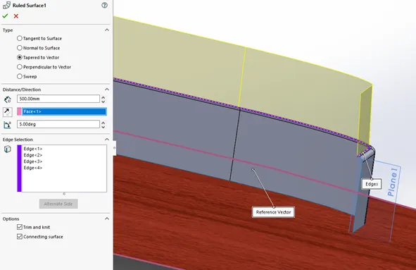
- The ruled surface feature is used, select the tapered to vector type > distance 500mm > select the face > trapper angle 5.00 degrees > select the edges > select trim and knit and connecting surface in options.
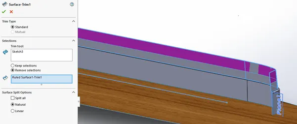
- Sketch the curve on the mid-plane > select the surface trim tool > select the sketch3 as trim tool > select the ruled surface > select the required remove section > select natural.
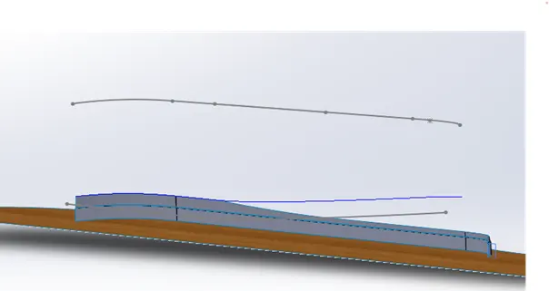
- To create the 3D curves, sketch the curve on the top plane by using convert entities and sketch other curve on the mid-plane by using entities and spline > Select the projected curves > select the created above sketches.
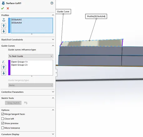
- Repeat the above sequence of steps to create other 3D curve > surface loft by selecting 3D sketch4 and 5 as profile and guide curves (open group1 and open group 2).
- Repeated the above steps and create another surface - loft (surface-loft 2).
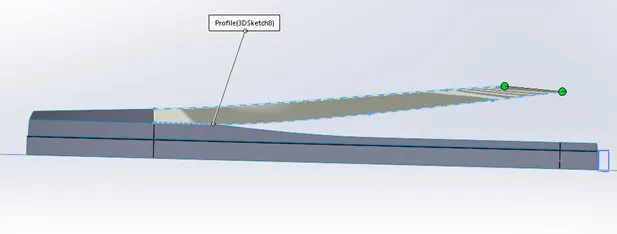
- Create a plane2 > draw a line on the plane 2 > surface sweep (select sketch9 as profile and 3D sketch10 as path) > surface-knit > create a plane4 > draw a sketch13 on the plane 4 > surface sweep (select sketch13 as profile and 3Dsketch12 as path) > Draw the sketch 14 on the mid plane > surface trim.
- Surface trim (shown in the below figure) > draw the curve on the mid-plane > surface-extrude (select the edge and length 3000mm) > surface trim (trim tool (select surface loft2), select surface-extrude2-trim0, select the remove selections) > surface knit.
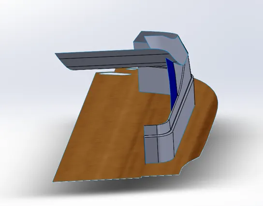
- Draw the 3D curve and convert entities > apply the surface-fill > apply surface-knit (select new fill-surface and remaining surface) > create a sketch20 on the surface-fill1 > apply surface trim > create a 3D sketch15 > select the surface loft (in profile select edges and sketch 25, and guide curves select 3D sketch14 and 3D sketch27) > surface knit.
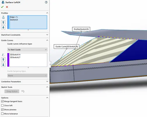
- Create a sketch27 on top plane by using convert entities > create another sketch 26 on the mid-plane by using spline line > apply the projected curve > select the sketch 26 and sketch 27 > created 3D curve4.
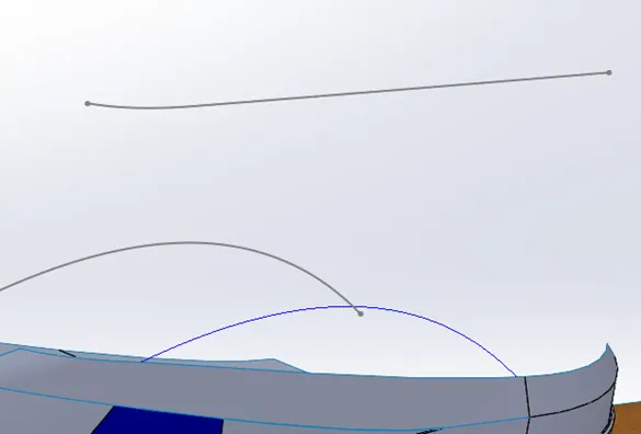
- Repeated above step and create sketch29 and sketch30 > apply projected curve and create 3D curve curve5 > select the surface-loft (select the curve4 and curve5 as profile and open group1 and opengroup2 as guide curves).
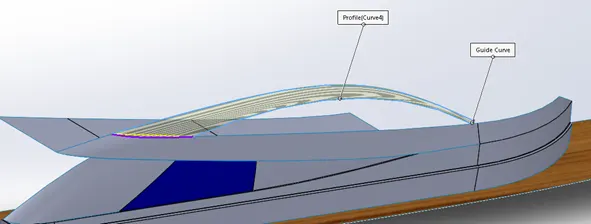
- Draw a sketch31 on the top plane and draw sketch32 on the mid-plane > apply the projected curve feature to create curve6 > surface-loft is selected from tool bar and lofted surface is formed by selecting 3D sketch17 and 3D sketch18 > second loft surface is formed from the 3D sketch20, 3D sketch21, 3D sketch19 and sketch33 (sketch 33 is created by offset entities).
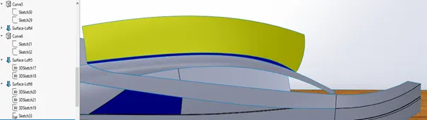
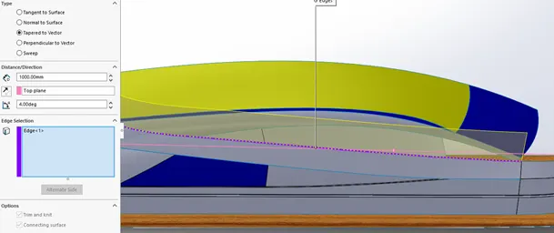
- Select the 3D sketch > create a 3D sketch22 by using spline curve > create a 2D sketch33 by using spline curve and given dimensions > select the surface-loft feature and select the above to sketches and result create surface as shown below > select the 3D sketch > select the edge and apply convert entities (3D sketch23) > applied ruled-surface (check the tapered to vector, select the top plane as face, tapered angle 4degree) > select the 3D sketch23.
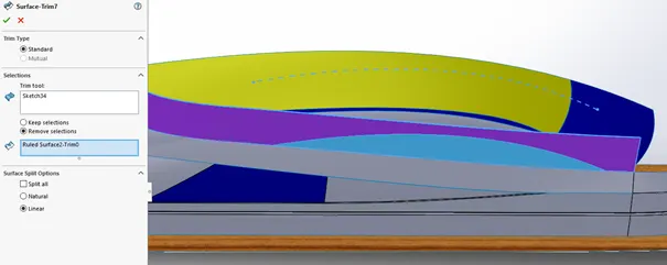
- Create a sketch34 on mid-plane > select the surface trim tool > select the sketch34 as trim tool > check remove selections.
- Create a surface loft8 to fill the gap between the surfaces created before > surface knit all the surfaces > apply the surface-extend and other following sequence such as surface-extend1 > surface-extend2 > surface-trim8 > surface-trim9 of steps are used to create > the feature of surface-loft, ruled-surface, surface-knit, and surface trim are repeated few times as per requirement and given dimensions.
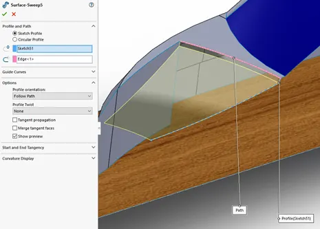
- To create front seating area on the superstructure, surface sweep feature is used. Created the required profile sketch51 and select the path.
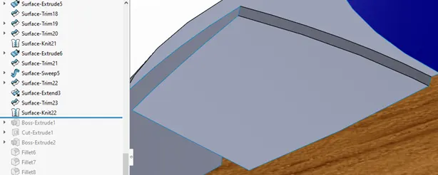
- The following sequence of steps and features are used to create the front area of the superstructure: surface-trim22 > surface-extend3 > surface-trim23 > surface-knit22.
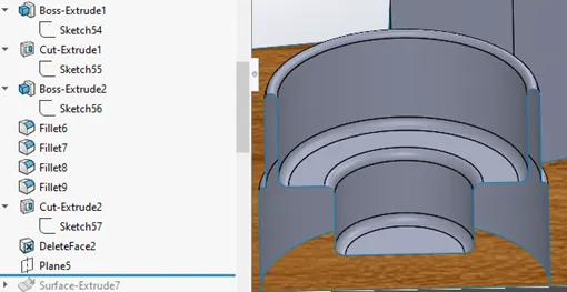
- The small water pool section is created by the following steps: boss-extrude1 (sketch54 a circular shape on the deck surface) > cut-extrude1 (sketch55) > boss-extrude2 (sketch56) > fillet6, 7, 8, and 9 > cut-extrude 2 (sketch57) > deleteface2 (by deleting the face, the solid feature is converted into surface feature).
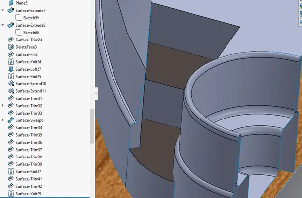
- Creation of steps relaxation area, create a plane5 > sketch59 is drawn on the plane5 and surface-extrude the sketch59 to create surface-extrude7 > draw the sketch60 on the surface7 > apply the surface-extrude > surface-trim > surface-fill2 > surface-knit24 > surface-loft27 > surface-extend10 > surface-extend11 > surface trim31 > surface-trim32 > surface-trim33 > surface-sweep 6 > surface-trim34 > surface-trim35 to surface-trim39 > surface-knit27 > surface-trim41 > surface-trim42 > surface-knit29 > surface-trim43 > surface-knit30.
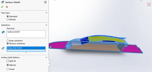
- Creating a solid form of superstructure of the yacht, apply the Surface-trim > select trim tool as surface-knit31 > select the deck surface > natural > knit the trimmed surface by using surface-knit.
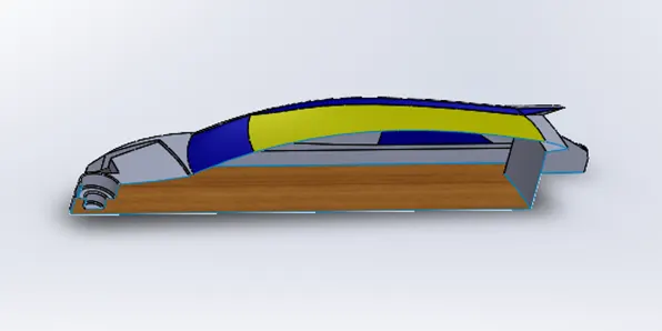
- Close the open side of the superstructure by surface-extrude the sketch69 and trim the excess surface by using surface-trim. Surface-knit all the surface together and check on the create solid option.
- Note: if the knitting operation fails, check for any open spaces between the surfaces created above.
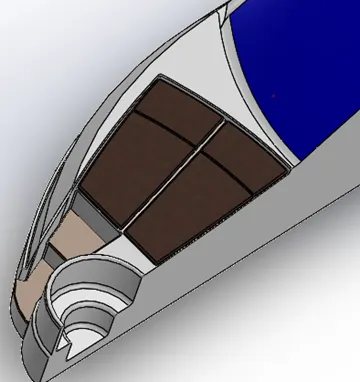
- Design of relaxation area in the front, create a surface-offset of the surface as shown in the figure > surface-trim the offset area to required shape and size > surface thicken > cut-extrude > apply dome and fillets to the solids > add attribute to the solids.
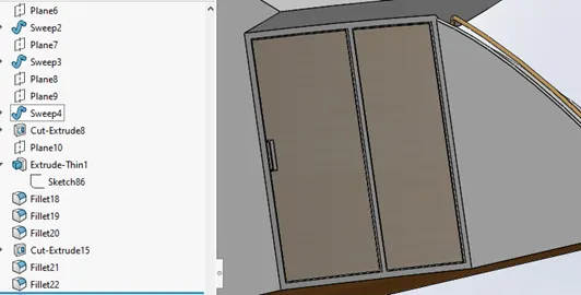
- Using sweep feature to create the handlebars at required places > create the doors to superstructure> cut-extrude > extrude-thin (select the thin feature of 12mm) > fillet.
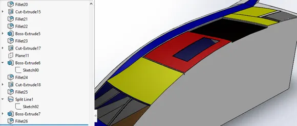
- Creating a window shield and sunroof on the top, Cut-extrude 17 > boss-extrude 6 > Cut-extrude18 > surface is divided into two surfaces using split Line 1 > Boss-extrude 7 > fillets > add attribute as colours and materials wherever required.
- Creation of side glass panels: create a plane parallel to the mid-plane (plane 12) > offset entities the edges on the plane 12 and cut-extrude (offset from surface) > fillet > repeat the above process and create another glass panel > split line 2 > boss-extrude the frame supports.
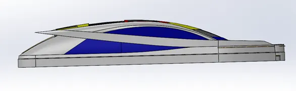
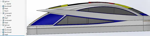
- Changes in the design after applying above sequence of features.
- Mirror all the created features about the mid-plane in following steps of Mirror1, Mirror2, Mirror3 and Mirror4.
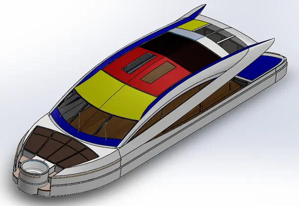
- The final design of the superstructure of the yacht.
- The top surface on the roof is offset to provide base to the design to the Radar Mast. This method will help us to assembly individual parts to create final product.
1.6. Radar Mast: Radar Mast is the eyes and ears of the yacht.
The following are sequence of the steps involved in the design of the Radar Mast.
- Create a new part file name “Radar_Mast” and import the base surface on which the radar mast will be erected from superstructure.
- To create a plane1 draw a reference sketch1 on the mid-plane.
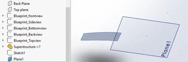
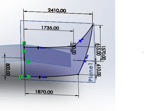
- Mirror the surface > draw the sketch2 as shown below with given dimensions > boss-extrude the sketch > apply fillets to the edges.
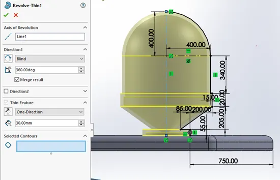
- Create a plane2 parallel to front-plane > create a sketch on the plane2 (as shown in the figure) > apply revolve feature (thin-feature 30mm > apply fillets to the edges.
- Creation of Antenna receiver by on the surface of boss-Extrude2 > boss-Extrude 3 > boss-Extrude 4 > apply fillets to the edges.
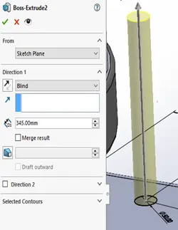
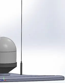
- Create a plane3 parallel to plane2 > create a plane4 on the mid-plane > to create sweep feature, draw a path (sketch8) on the plane3 and profile (sketch9) on the plane4 > Mirror the sweep1 about the palne2.
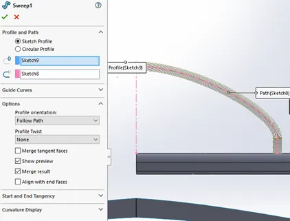
- Create a boss-extrude between to sweeps as shown in figure > create a 3D curve (curve1) for sketch11 and sketch12 > create a sweep2 by using sketch 13 (profile) and the curve1 (path).
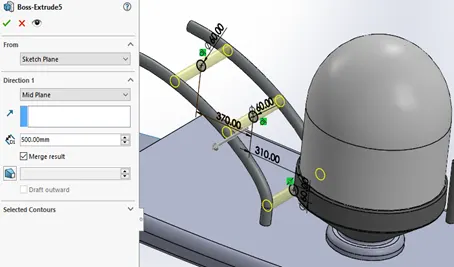
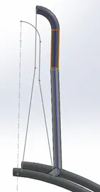
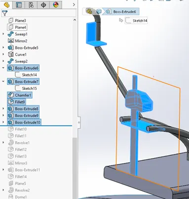
- The following sequence of feature to create as shown below, sketch14 > Boss-Extrude6 > sketch15 > Boss-extrude7 > chamfer1 > fillet9 > Boss-Extrude8 > Boss-Extrude9 > fillet 10 > fillet 11.
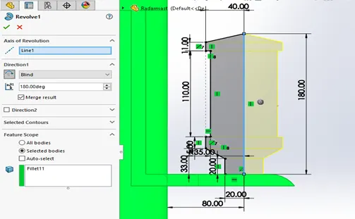
- Create a revolve1 of the following sketch below in the figure > mirror the revolve feature > Boss-extrude the support pillars and to mount radar mast on to the yacht > fillet > create a plane5 parallel to mid-plane > to create horn, create a sketch21 on the plane5 and revolve it > apply dome1 > fillet > shell.
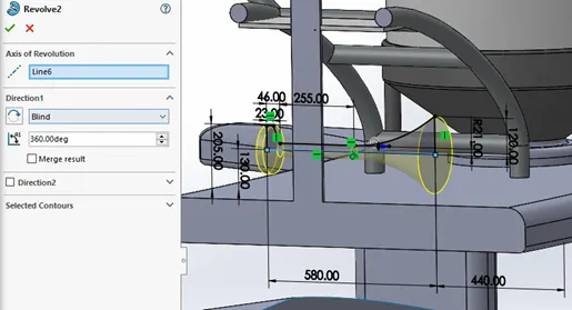
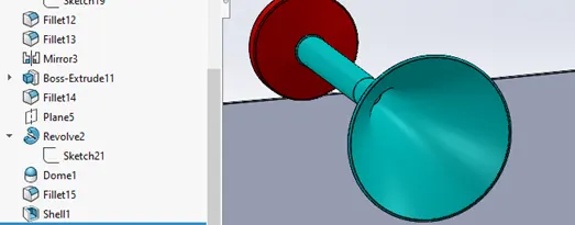
- To complete the radar mast, Mirror all the features created above, about the mid-plane.
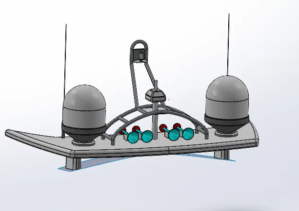
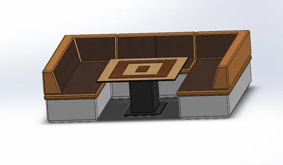
1.7. Designing of Middle Seat: These seats are design with a view of providing a comfort and luxury look adding to Yacht.
Procedure of creating the seat:
- Open the blueprint part file and save as with the new name.
- Import the hull only surfaces into the file.
- Create a sketch on the imported surface and add dimensions to the sketch and apply boss-extrude.
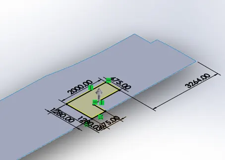
- Apply offset entities to the edges of the previous boss-extrude and any apply the boss-extrude feature.
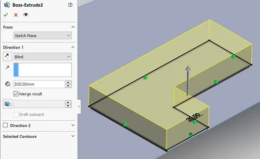
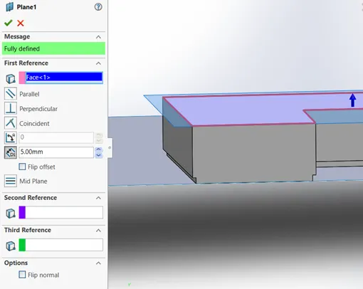
- Create a plane1, 5mm offset to the top side face of the boss-extrude.
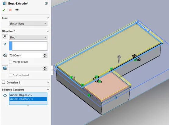
- Create a sketch3 on the plane1 and use trim tool to create two close regions. Apply extrude feature to the regions.
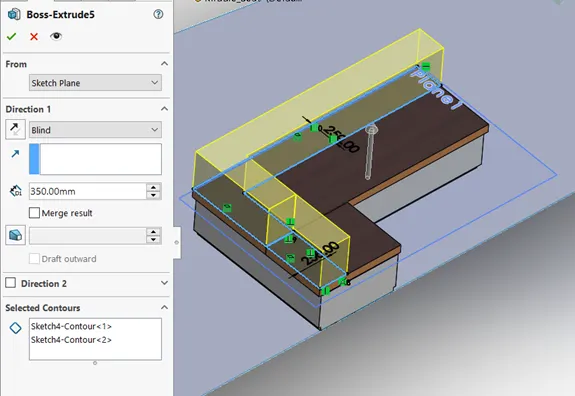
- Creating plane2, draw a sketch on the palne2 and boss-extrude it.
- Apply chamfer and fillet features to required edges as per as given dimensions.
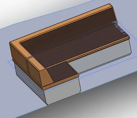
- Apply the mirroring feature.
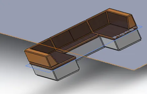
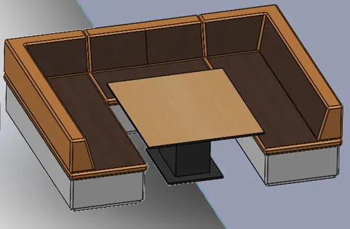
- To create table, draw a series of sketch on the deck-surface and boss-extrude to form table.
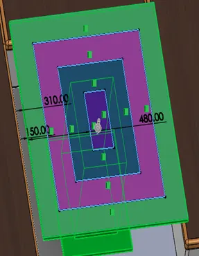
- Draw the sketch on the top surface of the table as show in the figure below and cut-extrude.
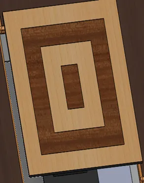
- Add material properties to the respective surface and bodies.
Designing of Rear side:
- Open the blueprint file > save as the file > import the deck surface from the hull.
- Create a plane1 parallel to the deck surface > create a sketch1 on the midplane > draw a sketch2 on the plane1 > surface-sweep1 (select sketch1 as profile and sketch2 as path).
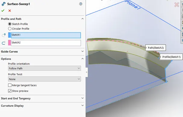
- Surface-sweep feature.
- Offset the surface > draw a line on the plane1 > apply surface trim > Ruled surface > Surface knit > again apply surface trim.
a)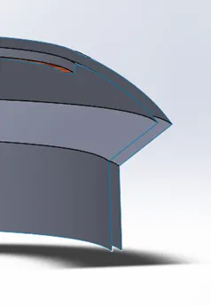
b)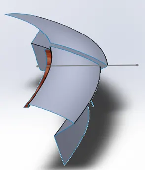
c)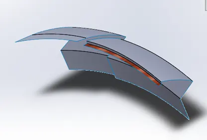
a) Surface-offset feature b) surface-trim1 and c) surface-trim.
4. Create a plane2 and plane 3 as shown in the below figure.
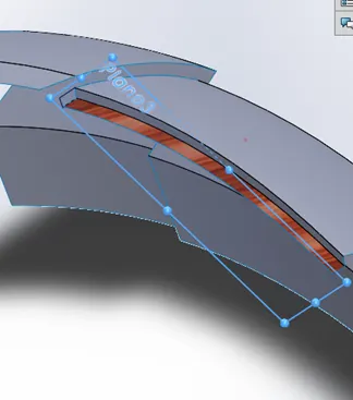
- Convert entities the edges on to plane2 > surface Sweep2 > surface extend > surface trim > surface knit.
a)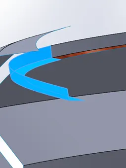
b)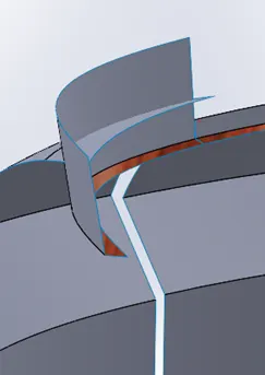
c)
a) surface-sweep, b) surface-extend and c) surface-trim.
- To close the left side end and to fill the gap in the middle of the surfaces, a curve is drawn on the deck surface and extrude > surface trim > surface loft > surface knit.
a)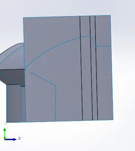
b)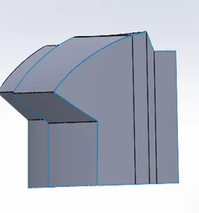
a) surface-extrude and b) after surface-trimming.
c)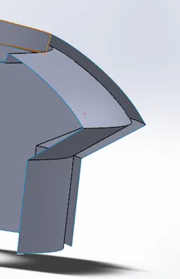
d)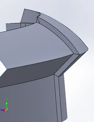
c) between the surface-loft and d) after surface-loft.
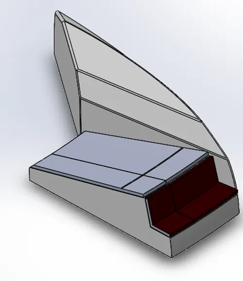
- To close the front face, surface-extrude the edge till the deck surface > surface knit > surface-loft (closing the right side) > surface-loft (closing the lower side of the rear seat) > surface knit (click the create solid).
a)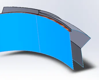
b)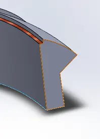
a) surface-extrude and b) surface-loft.
c)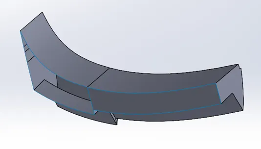
d)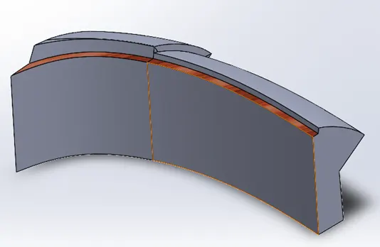
c) surface-loft to fill the gap and d) surface knit, create solid.
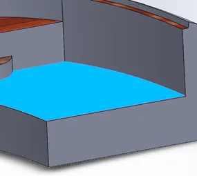
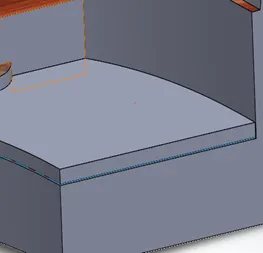
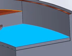
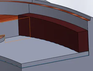
- Draw a sketch on the deck-surface > boss-extrude1 > draw a sketch on the extruded surface > boss-extrude > draw a sketch16 on the front plane > cut-extrude > boss-extrude and cut-extrude for arm rest and cup holder.
a)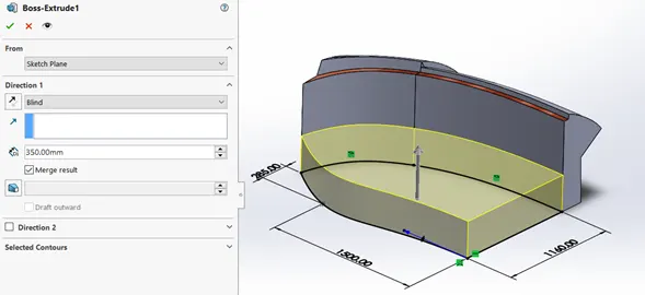
a) boss-extrude1 to create seating area.
b)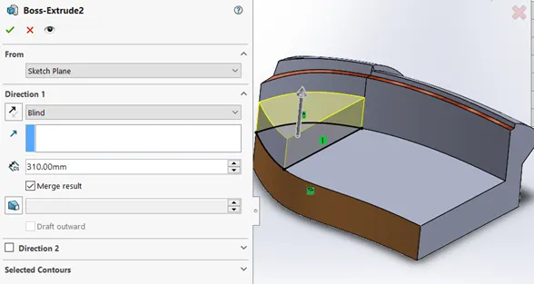
b) boss-extrude2 to create storage space.
c)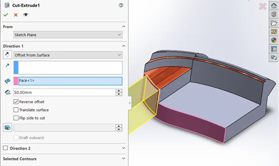
c) cut-extrude (thin-feature).
d)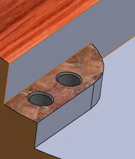
d) cup-holder.
- Designing of cushion, apply surface-offset to top surface > offset the edges > apply surface-trim > boss-extrude > surface-offset > surface-trim > boss-extrude > chamfer and fillet.
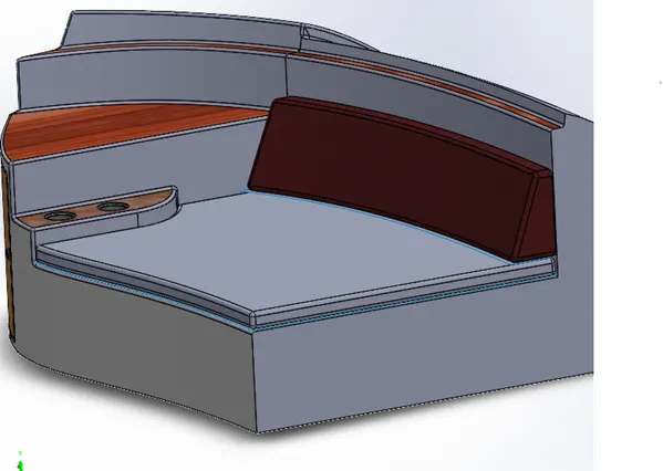
- Mirror all the created feature to finish rear seat and attribute and material properties.
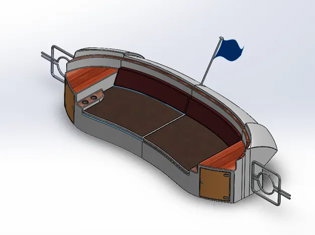
Rear seat
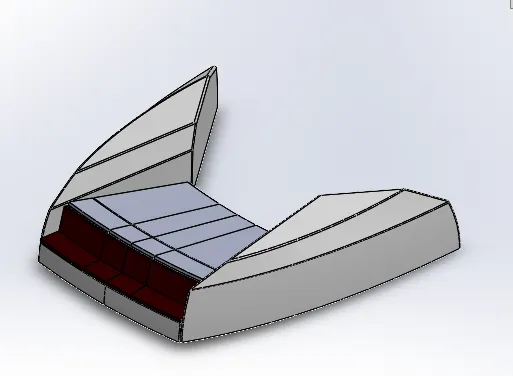
1.8. Front Seat:
- Open the blueprint and save as the file with a name ‘front Seat’.
- Import the Hull file and select the surface only.
- Create a plan1 > draw sketch1 and sketch2 > apply surface-sweep1 > draw a sketch3 on the deck-surface > apply the surface-extrude to sketch3 > surface trim > surface-fill the gaps between the created surface.
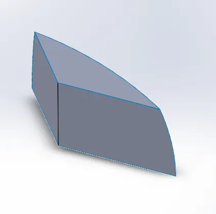
- Apply surface-trim on the top surface and side-surface > surface-loft the gap > surface-trim > knit all the surfaces > chamfer.
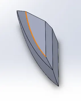
- Apply revolve feature as shown in the below figure.
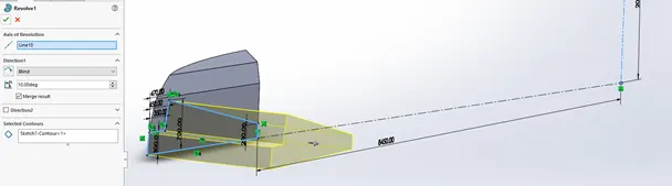
- Apply cut-extrude feature as per given dimensions and it’s shown in the below figure.
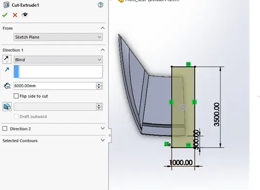
- Apply revolve2 to create cushion and cut-extrude.
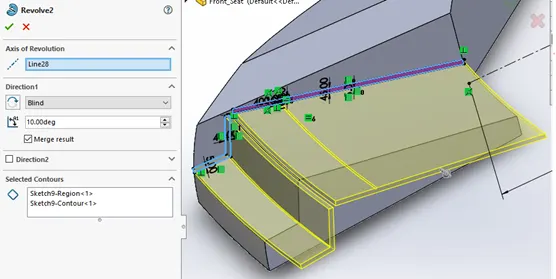
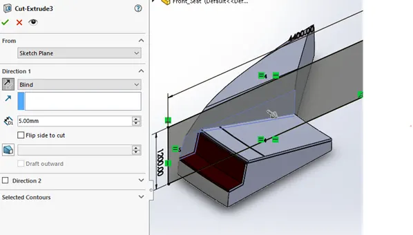
- Apply chamfer and fillet to all the required edges.
1.9. Yacht Assembly:
- Open the new assembly file and save file with the name ‘YACHT’.
- Select the insert components > open documents > select hull part and fix the location.
- As we design all the parts on the reference of the deck surface of the hull. The assembly of the part are very simple and individual parts have been fixed in the respective location.
- Select the insert components > open documents > select the individual parts of the yacht such as superstructure, radar mast, front seat, Middle seat, Rear seat.
- To fixture of garage door, Select insert components > open documents > apply the mates feature concentric and coincident.
- To fixture of propeller, select insert components > open documents > apply the mates features of concentric and coincident.
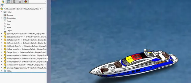
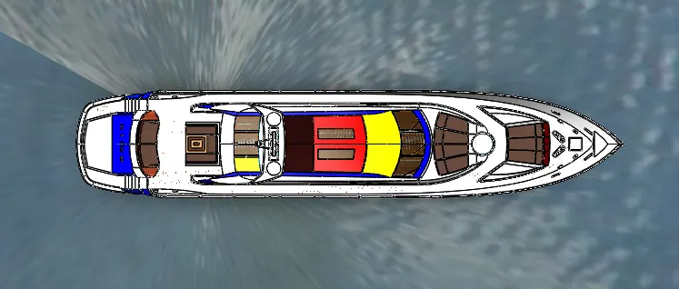
- Top view.
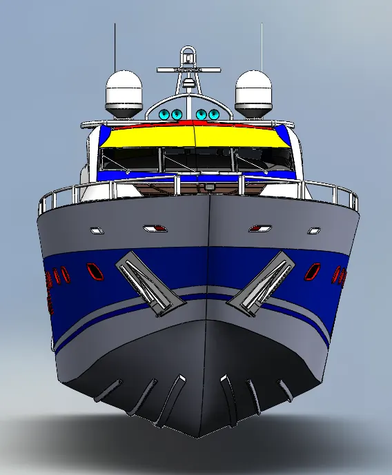
- Front view.
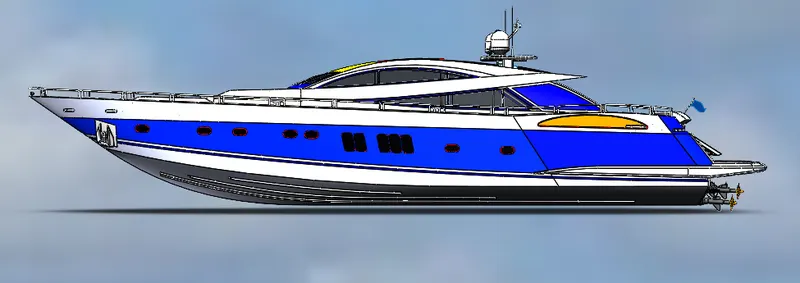
- Side View.
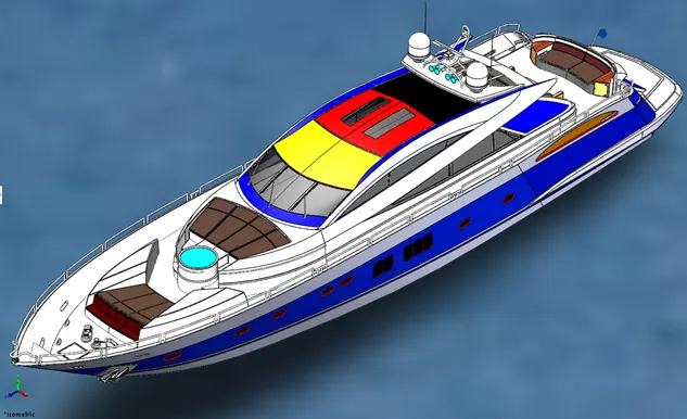
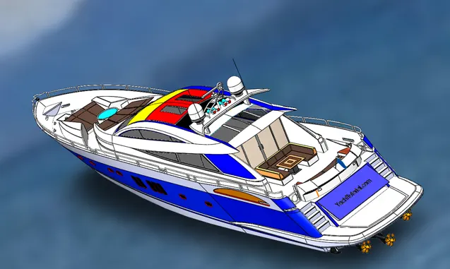
Conclusion:
- The individual parts of the yacht are modelled.
- The parts are inserted into the assembly and Yacht is assembled.
- The decals are added to the surfaces and lights are rendered with the use of the photo view 360 and Solid works Visualize.