Advanced Sheet Metal Design Using NX Cad Challenge_7_ Metal bracket-II
Title:- To modelling Metal Bracket-II and Drafting Using Sheet Metal Application Using NX CAD.
Objective:-
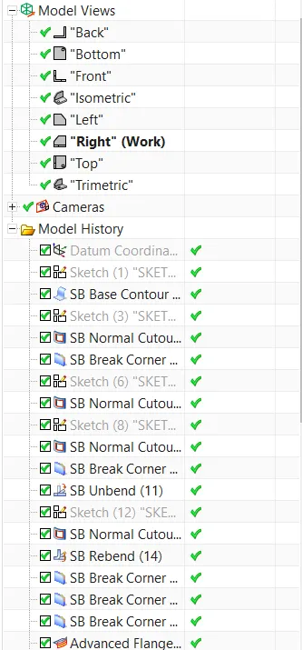
- In this project we have create the Metal bracket-II and using various feature tool like Countour Flange, Normal Cutout,Corner Break, Unbend and Rebend, Hole, Advanced Flange and Gusset.
- To create 2D Drawing Sheet and Detailed Drawing Sheet.
Introduction:-
In mechanical engineering a bracket is any intermediate component for fixing one part to another, usually larger, part. What makes a bracket a bracket is that it is intermediate between the two and fixes the one to the other.Within companies, different modeling techniques are used, often different solutions apply and data is exported for subsequent further design. Siemens NX CAD bundles these various techniques in one solution. For example, you can perform parametric modeling, quickly adapt designs with Synchronous modeling. The benifits of NX CAD is Deliver more innovation,Reduce product design costs,Improve quality.
Design methodology:-
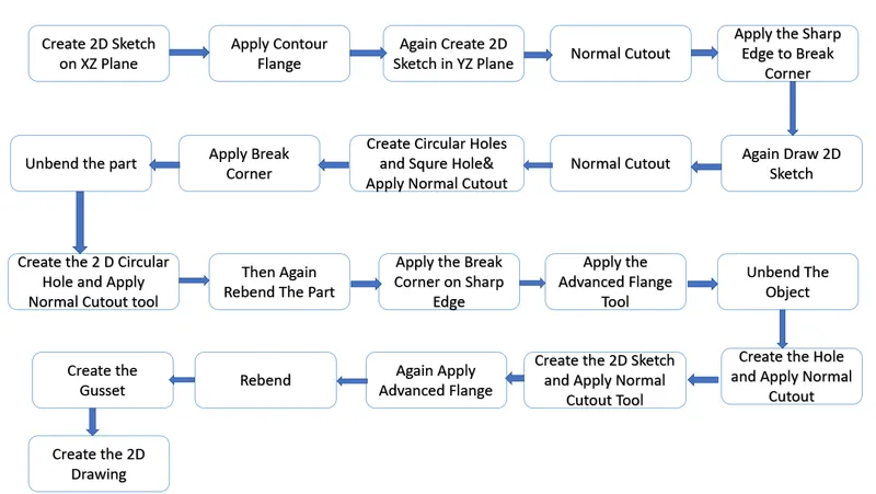
Description to tools/ Features used designing for Bracket-II:-
Create The 2D Sketch:-
Created a 2D sketches the for sheet metal parts and Used the direct sketch tool to add curve,dimensions and constraints.
Contour Flange:-
This command used for Creates main base flange or second flange by extruding sketch in sheet metal application.
Normal Cutout:-
The Extracts volumes from sheet metal by using sheet metal production principles. Cutting faces will be perpendicular to the sheet metal surface. Look figure for the difference between the normal cutout and extrude subtract.
Break Corner:-
This feature breaks the sharp edges in the corners and makes it round or adds chamfer. It is like the fillet feature in some other cad software.
Unbend:-
This command is used for Flattens sheet model through selected bends.
For Using “Unbend” command:
- Activate the “Unbend” command.
- Select the stationary face of the sheet metal.
- Select edges to bend.
- Click middle mouse button or “Ok” to finish.
Rebend:-
Rebends, unbended feature of the sheet metal model. It uses after the “Unbend” command If needed.
Hole:-
Hole a command that users could create or drill standard sized holes with it. This command is called Hole and you can activate this command by clicking on it. You can create various kinds of holes that generally used in mechanical structures according to accepted standards.
Advanced Flange:-
Advanced Flange adds flange along the edge using the reference face or bend angle. · Flange Properties namely Length, angle, length reference.
Gusset:-
Gussets are used to strengthen a flange without the need for secondary processes such as welding. A general guideline suggests that the width and depth of gusset at an angle of 45 degrees is directly proportional to the radius and material thickness.
2D Drawing Sheet:-
To create a 2D drawing from a 3D model using the NX Drafting application.
Final look Model:-
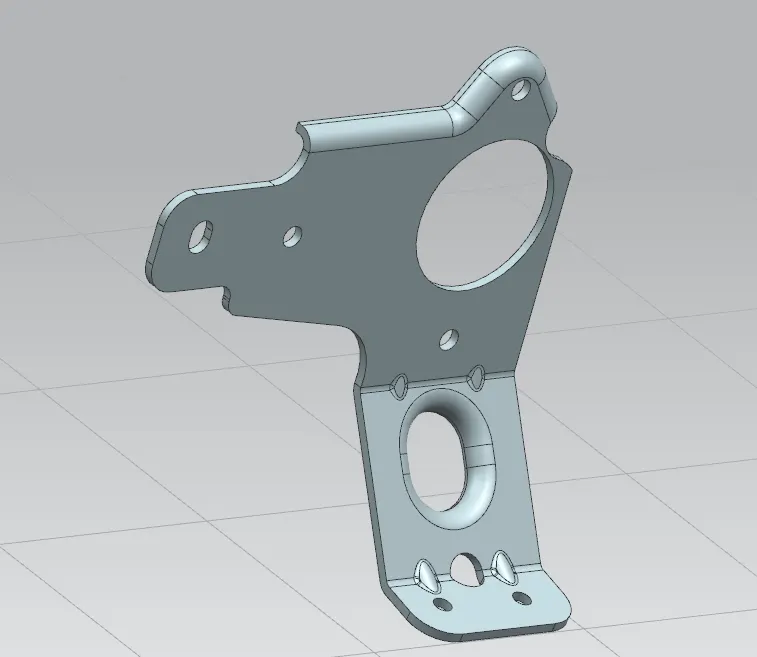
Metal Bracket-II 3D Part:-
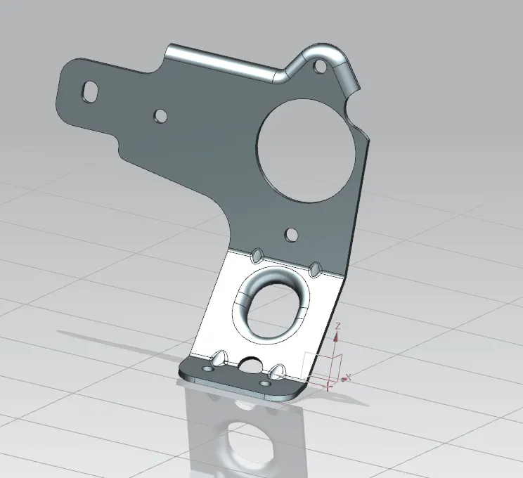
Model View (Front View, Side View, Isometric View and the Top View):-
Front View:-
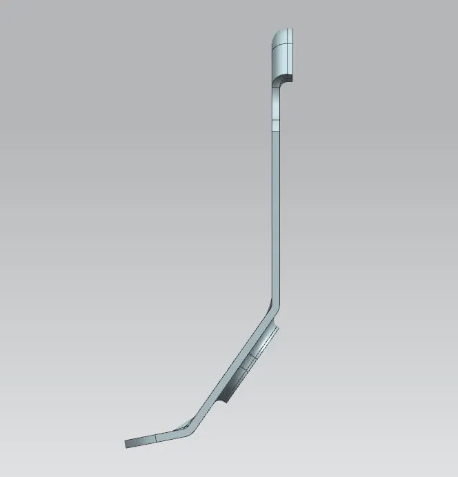
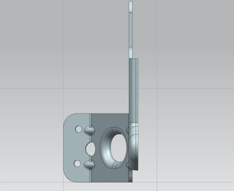
Side View:-
i] Left View:-
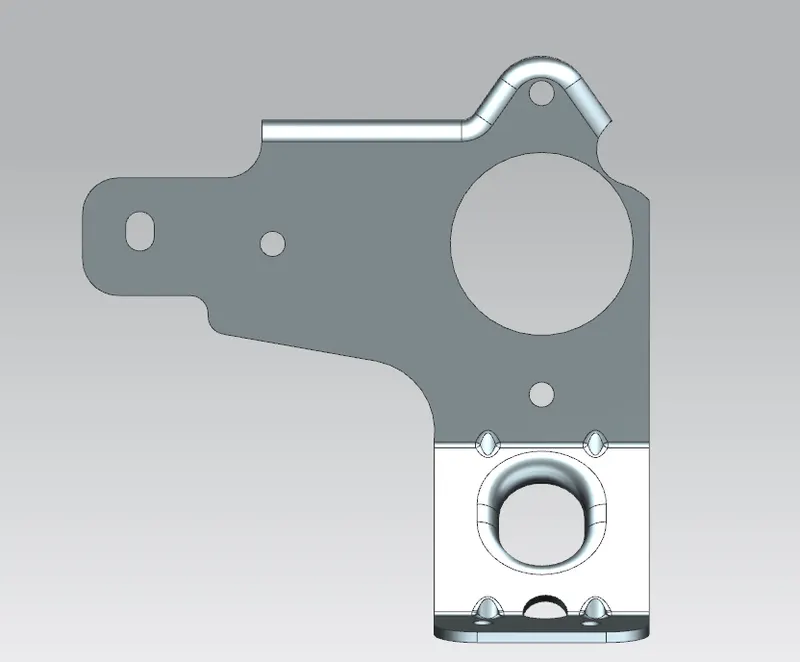
ii] Right View:-
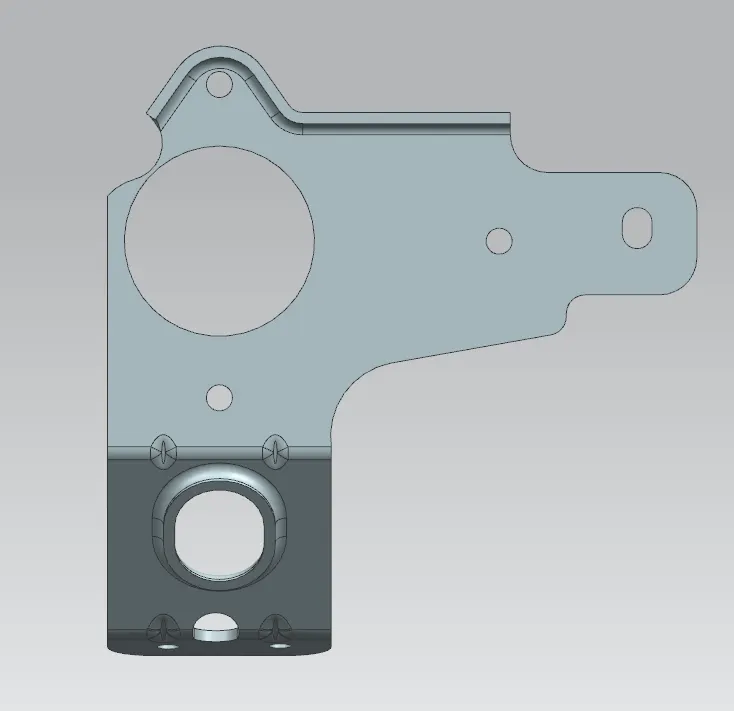
Top View:-
Isometric View:-
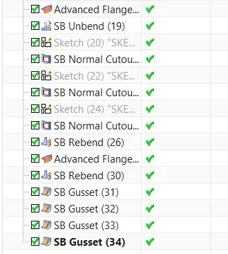
Tree Feature:-
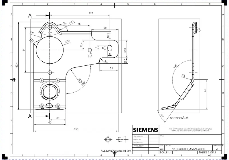
Metal Bracket-II 2D Drawing Sheet:-
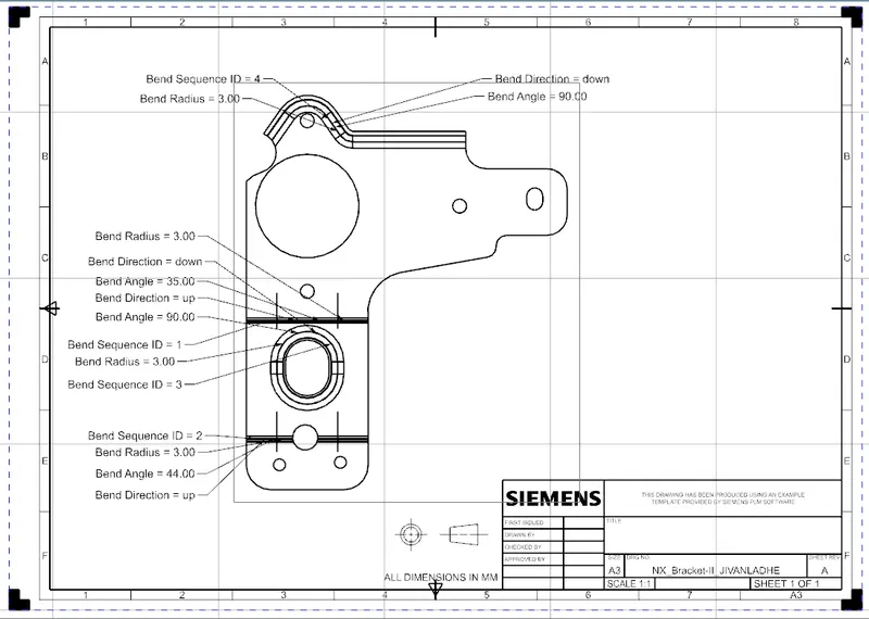
Detailed Drawing Sheet:-
Conclusion:-
Thus a Created Metal Bracket-II is Completely Design and Drafting by Using NX CAD Sheet Metal.