Advanced Sheet Metal Design Using NX Cad Challenge_7_ Metal bracket-II
DESIGN OF SHEET METAL BRACKET-II USING NX CAD
OBJECTIVE:-
• To understand the 2d drawing in the right way and design a metal bracket from a complex 2-dimensional diagram.
INTRODUCTION:-
• we have created a sheet metal bracket in the previous session. here we are going to create a bit complex geometry bracket from a given give 2-dimensional drawing. as we know these brackets are used in so many applications like tv mount.
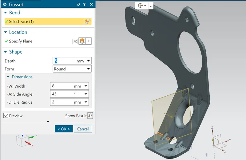
• To increase the strength and stiffness of the sheet metal part here we are going to use gusset and flanges. it will hekp to prevent from frature failiure.
• most importantly here we are going to learn about converting 2-dimensional sketches into sheet metal parts.
DESIGN METHODOLOGY:

DESCRIPTION:
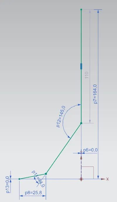
SKETCH:- It's a basic command to draw 2D models. draw a sketch on the YZ axis here I used counter flange commend.
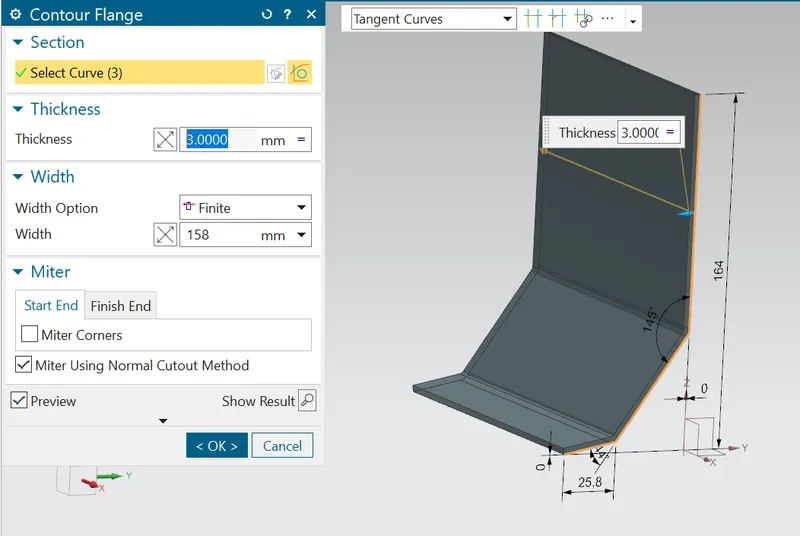
Contour Flange: -
You can create secondary contour flanges around bend edges. If you do not want to create the contour flange on the bend region, select only the tab edges and not the bend edges.
SKETCH:- Draw a sketch on the XZ axis to make a normal cutout.
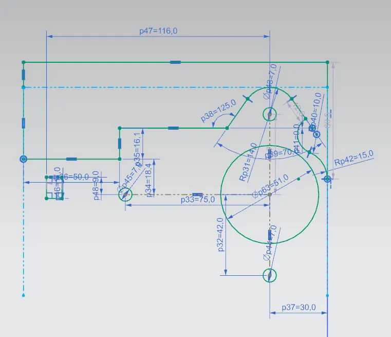
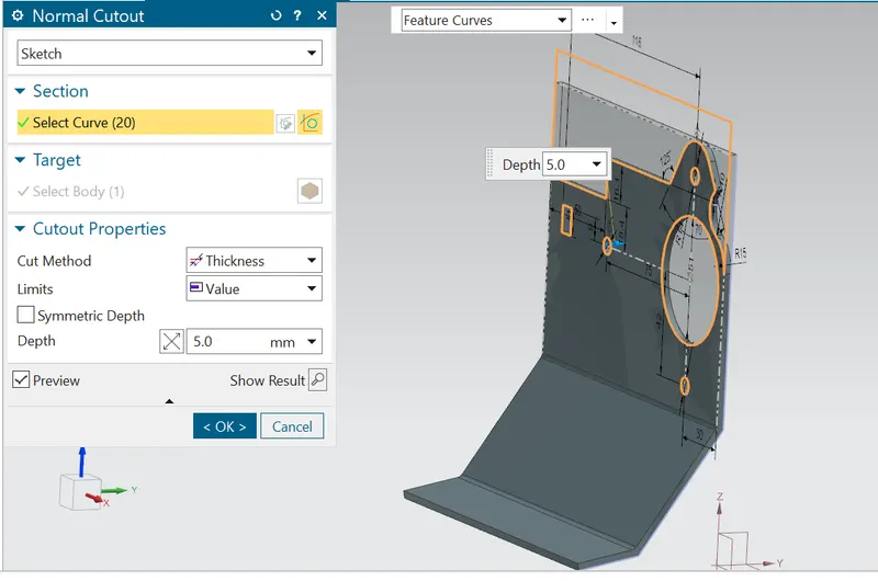
Normal cutout:
Normal Cutout command extracts volumes from sheet metal by using sheet metal production principles. Cutting faces will be perpendicular to the sheet metal surface.
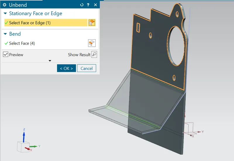
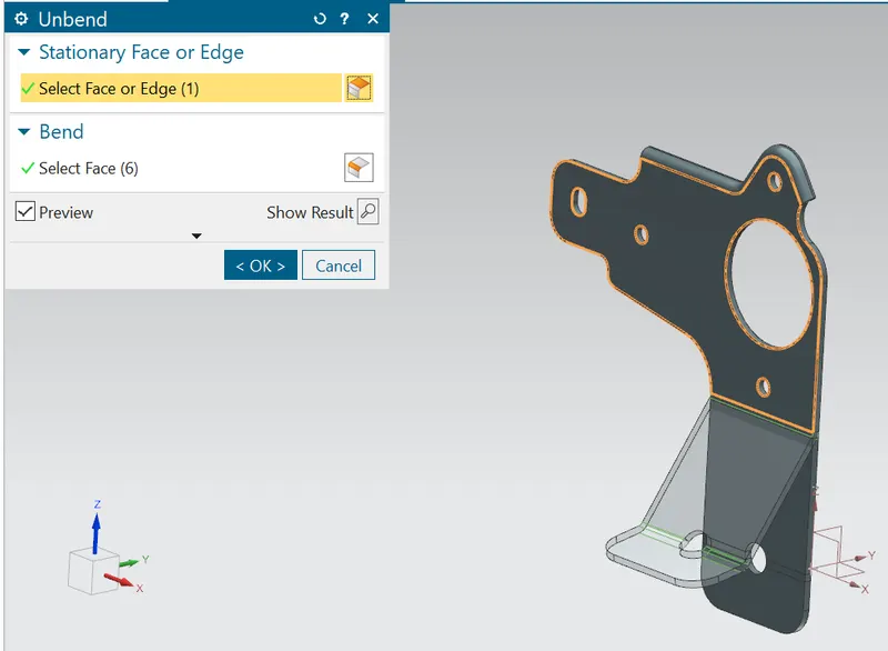
Unbend:- This command is used to flatten the 3D model by selecting one stationary face.
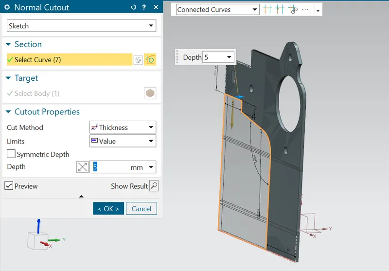
SKETCH:- Draw a sketch on the XZ axis to make a normal cutout.
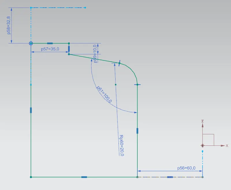
Normal cutout: To make an exact profile as given
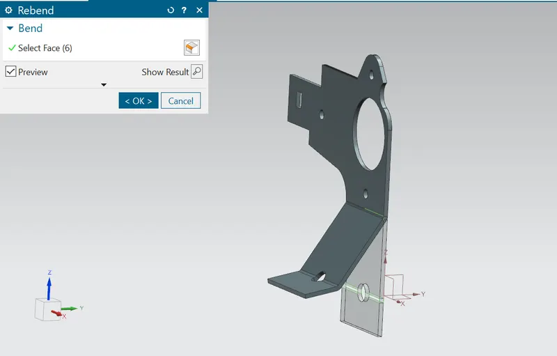
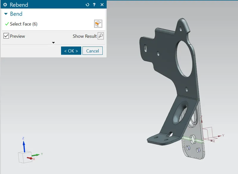
Rebend:- This command is used to rebend the flatten sheet material from the flatten face to a profile.
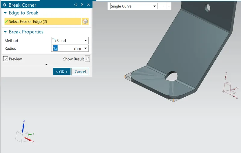
Break corners:- This command is used to round or chamfer sharp corners of a tab or flange.
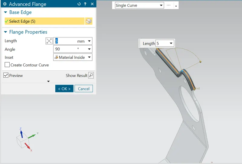
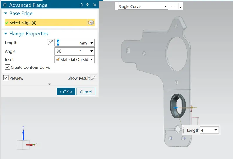
Advance flange:-
Use this command to add a flange along an edge using a bend angle or a reference face. The edge and reference face can be curved.
This command is useful when you want to create non-linear flanges, or when you work with sheet metal support structures in complex assemblies. You can use existing geometry as a reference to define the flange dimensions.
When you unform an Advanced Flange feature, the unformed feature is integrated with the feature created by the Sheet MetalFlat Pattern command.
Unbend:-
Advance flange:-
Rebend and Gusset:-
Different views:-
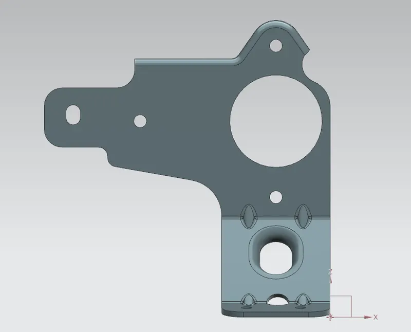
Front view:
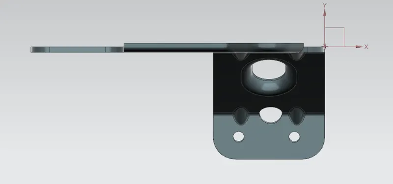
Top view:
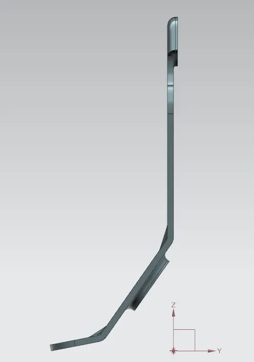
Side view:
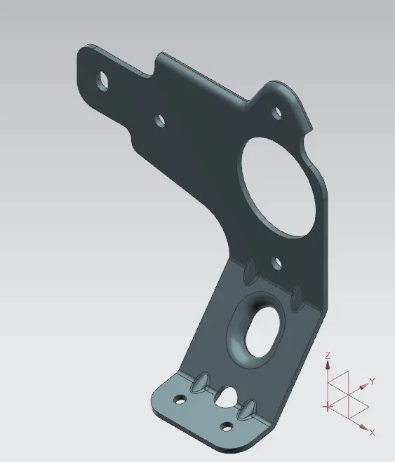
Isometric view:
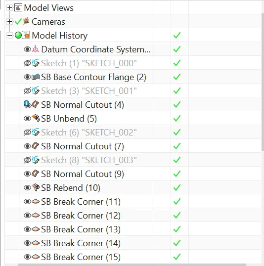
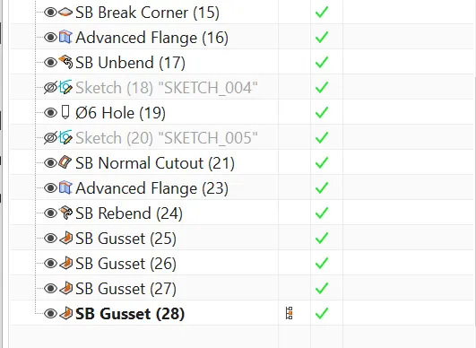
Tree:-