Advanced Sheet Metal Design Using NX Cad Challenge_7_ Metal bracket-II
TITLE OF THE PROJECT
To create a metal bracket II using sheet metal application of NX CAD
OBJECTIVE
The main objective of this project is to learn Bracket designing part 2 with the help of various tools features of NX CAD sheet metal application.
To learn about the fundamentals, basics and advanced commands of NX Sheet metal.
INTRODUCTION
In this project, we will be learning on how to design the bracket part 2 using NX sheet metal application and various tools and features of NX Sheet metal. To create this, sketch is created in the given plane and then steps in the pdf are followed in the proper way to create the metal bracket.
The various features used to design metal bracket are:
- Sketch
- Contour Flange
- Normal Cutout
- Corner break
- Unbend
- Rebend
- Advanced Flange
- Unbend
- Simple hole
- Gusset
DESIGN METHODOLOGY AND DESCRIPTION
WORKFLOW
- Sketch in YZ plane
- Sketch in XZ plane
- Contour flange of XZ plane sketch
- Remove unwanted sketch using normal cutout
- Corner break
- Advanced flange of top arc
- Unbend
- Hole creation
- Normal cutout of circle
- Advanced flange of normal cutout
- Rebend the unbend edges
- Gusset creation
DESIGN METHODOLOGY AND EXPLAINATION OF FEATURES USED:
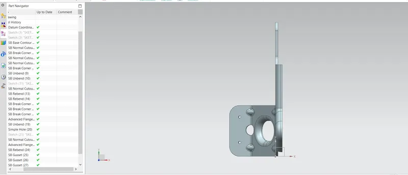
In the first step, we have created a sketch in YZ plane and then a sketch is created in XZ plane also. The sketch of XZ plane extruded using Contour flange feature.
CONTOUR FLANGE: It creates a base feature by extruding a sketch along a vector and adds material by sweeping the sketch along the edge.
The next step is to remove the unwanted sketches and materials using the normal cutout feature along the direction of the sketch created.
NORMAL CUTOUT: This feature is used to remove the unwanted material from the sheet body
After that, the corners were rounded using the break corner feature.
CORNER BREAK: This feature is used to round or chamfer the sharp corner of tab or flange.
After that, the bend edges were converted to straight using the unbend feature.
UNBEND: This feature is used to unbend the bend edges of the sheet.
Again, the corners were break using break corner feature and its rounded.
After that, advanced flange is created on top arc of the sheet body.
ADVANCED FLANGE: This feature is used to add a flange along an edge using a bend angle or a reference face. The edge and reference face can be curve.
After that, simple holes were created and the sketch was drawn with proper dimension to remove the material of sketch using normal cutout.
The next step is to create a advanced flange of the recently created normal cutout.
After that, the unbend edges were rebend again using rebend feature
REBEND: Tis feature is used to restore an unbend feature to its previous bent state along with any feature added after unbend feature.
Finally, 4 gussets were created on the given faces and planes.
GUSSET: It creates a stiffening gusset of the part.
MODEL VIEWS:
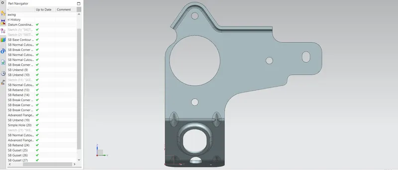
TOP VIEW
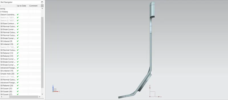
FRONT VIEW
RIGHT VIEW
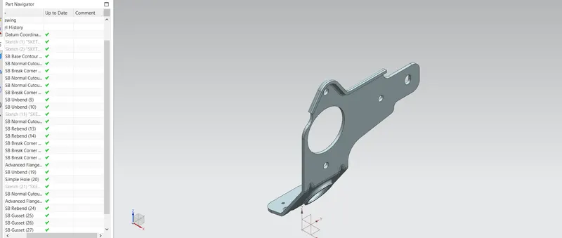
ISOMETRIC VIEW
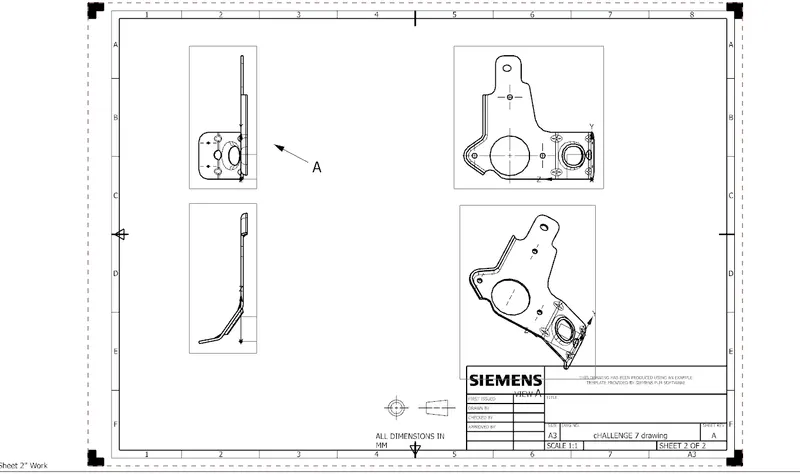
DETAILED DRAWING SHEET