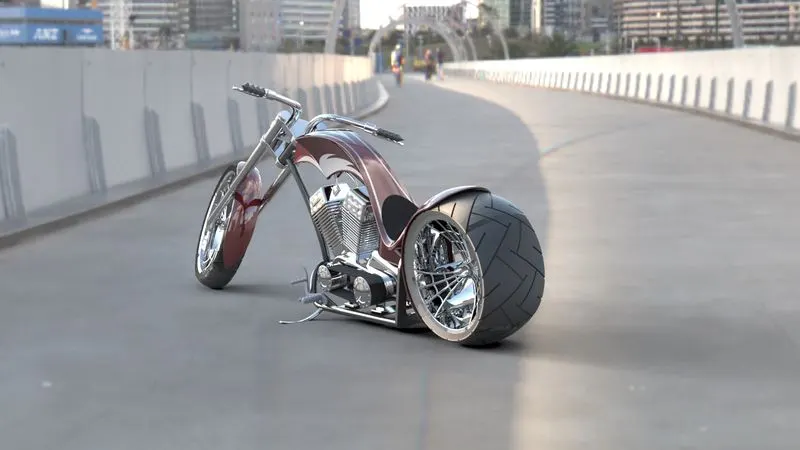
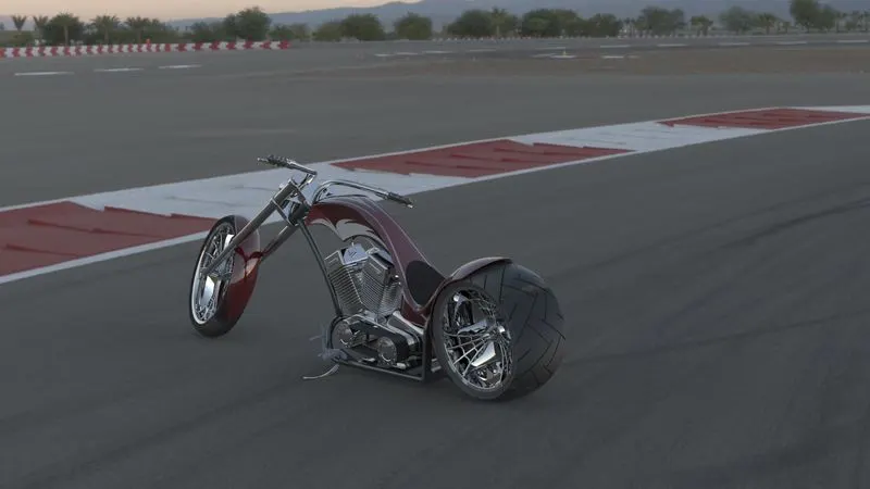
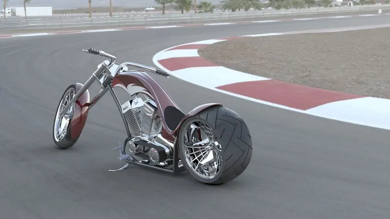
Photo Realistic Rendering
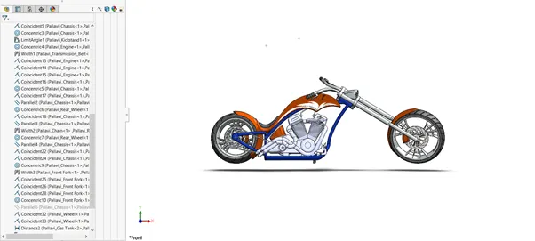
TITLE OF THE PROJECT
Modelling of American Chopper and make it realistic with rendering tools and Photo View 360.
OBJECTIVE
- The main objective of this project is to build the model of American Chopper and perform all the rendering operation
- To learn the basic and advanced tools in solidworks
- To create the model as realistic as possible with the help of rendering operations.
INTRODUCTION
For making American Chopper, first of all modelling modelling of various sub components is done and then finally all the components are assembled to make a final model of the Chopper. Modelling includes sketching of the components and then making these components in 3D. The features used for 3D modelling are:
- Extrude
- Boss
- Fillet
- Lofted Boss
- Revolve
- Extrude Cut
- Shell
- Trim Entities
- Split
- Dome
- Chamfer
- Circular Pattern
- Linear Patter
- Surface creation
- Shell
- Offset etc
The various sub components that make the chopper are as follows:
- Transmission Belt
- Kickstand
- Chain
- Front Fender
- Rear Fender
- Pedal
- Front Wheel
- Rear wheel
- Oil Tank
- Front Fork
- Chassis
- Engine
- Gas Tank
DESIGN METHODOLOGY AND DESCRIPTION
TRANSMISSION BELT
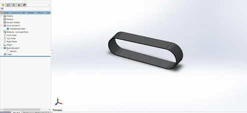
Transmission Belt is used to transfer the power between the shafts, the engine and gear box
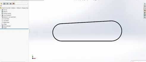
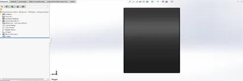
It is designed by creating a sketch with proper and appropriate dimensions and then it is transformed into 3D using the following features. Finally the edges of the transmission belt are smoothen with the help of fillet feature.
Extrude: This feature is used to create the sketch into solid model
Fillet: This feature is used to smoothen the corners/edges.
KICKSTAND
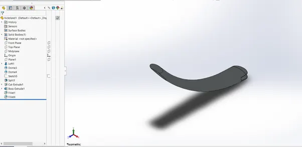
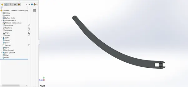
A kickstand is a device that is made with a piece of metal which is used to keep the bike stand upright without leaning towards another object.
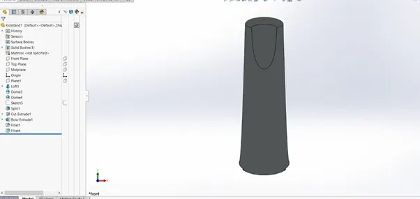
To design a kickstand, first of all a sketch with curved surface is made and then two ellipse at the edges is sketched. The ellipse and the curved surface are made in different planes.
After that, the sketch is converted into 3D with the following features.
Lofted/Boss: With the help of this feature, a smooth 3D surface is created by taking the smooth curve and the two ellipses and then it is further made into realistic kickstand with the help of following features.
After applying loft feature, the surface of the two ellipses are smoothed using the elliptical dome feature.
Split: With the help of Split feature, the surface through smaller section of ellipse is slightly cut
Cut Extrude: With the help of this feature, a cut is made after sketching in the mid of the larger ellipse surface side.
Boss Extrude: A circle is sketched between the cut extrude of larger ellipse, then its converted to 3D with the help of Boss extrude.
Fillet: The edges are smoothed with the help of this feature.
CHAIN
This is a device used to transfer power from pedals to the wheels
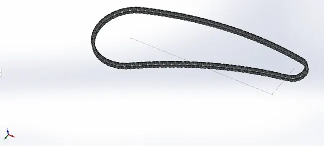
Chain is designed by first creating a large sketch to display the proper shape and then two small sketches are created which are linked and named as Chain link 1 and Chain link 2
After that these links are extruded and then these are joined by using another boss extruded sketch and then another boss extrude is crated to join these to make the desired structure of chain. The edges are smoothened with the help of fillet . This structure is made multiple time using the pattern feature and then the patterned features are extruded to create the the required structure of chain. The process is repeated again and again and finally the complete structure of chain is built
After that the proper chain is made with the following features
Sketch: Chain links are sketched with roper dimensions.
Extrude: Chain links are extruded to make it 3D and it is adjusted with proper guidance of sketch
Curve pattern: Chain links are patterned with help of this feature along the smooth guide curve with proper counting.
Mirror: After all the sketches, pattern and extrude , the feature below the main sketch is mirrored with reference to the main sketch drawn.
FRONT FENDER
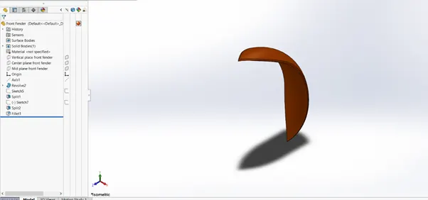
Front Fender is also known as Mudguard is used to prevent the sand, mud, other liquid sprays from being thrown into the air by rotating tyre.
To design front fender, a proper sketch is made with different planes and then its revolved upto a certain angle.
After revolve, to make a proper shape and nice look for fender, a sketch is drawn in another plane and its split to make a proper and smooth finishing and remove the desired material to make the fender look realistic.
Features used:
Revolve: Revolve is used to create the sketch in a revolve manner at some angle. Here revolve is used for the fender to spread to some angle along the required axis.
Split: Split feature is used to separate a single body into two bodies.
Fillet: This feature is used to smoothen the edges/corners.
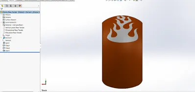
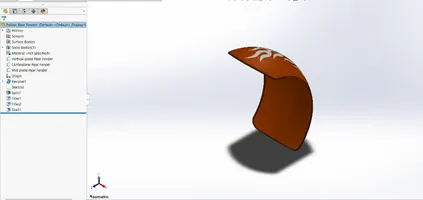
REAR FENDER
Rear fender is used above the rear part of the wheel. The purpose of rear fender is also the as that of front fender.
To design a rear fender In solidworks , the process for designing is similar as the front fender. First of all , a sketch is created and it is revolved about a certain angle to make the desired feature. Then using a slit feature the body is separated and the extra surface is removed. The edges are smoothened using the fillet feature and at last the solid body is shelled to have a proper fit on the rear portion of the bike.
To design the rear fender part, the following features are to be included.
- Sketch: Drawing of a 2D component in a software is called as a sketch.
- Revolve: Revolve is used to create the sketch in a revolve manner at some angle. Here revolve is used for the fender to spread to some angle along the required axis.
- Fillet: This feature is used to smoothen the edges/corners
- Split: Split feature is used to separate a single body into two bodies.
- Shell: Shell feature is used to vacant the extra material.
OIL TANK
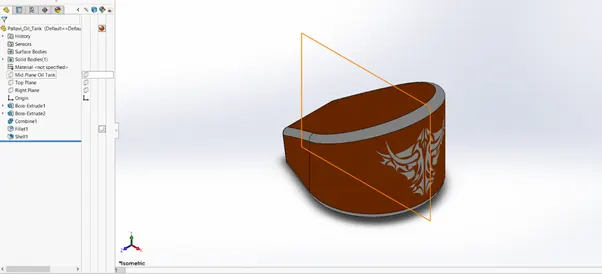
Oil Tank is device used to store the fuel for heating and thus generating power to drive the system.
Oil tank is modelled by first creating a sketch in a suitable plane and performing a extrude operation to convert it into 3D after that another sketch is created and both are taken common by performing the combine subtract operation.
The features used in this are:
- Boss Extrude: Boss extrude is used to convert a 2D sketch into 3D model.
- Combine Subtract: This feature is used to remove the parts that are not required with combination.
- Fillet: This feature is used to smoothen the edges/corners
- Shell: Shell feature is used to vacant the extra material.
PEDAL
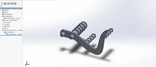
Pedal is used to operate the bike that the rider pushes with their foot print to operate the bike.
To design a pedal, I have created a raw sketch and then I have extruded separately each and every part of the sketch, after which chamfer is applied.
The features used in creating pedal:
- Extrude: Boss extrude is used to convert a 2D sketch into 3D model.
- Pattern: Pattern feature is used to make the duplicates to any number of instances with proper spacing/angle.
- Chamfer: This feature is used to cut the corner/edge at sharp angle/distance
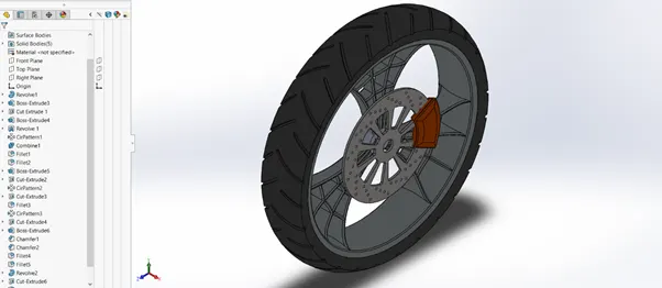
FRONT WHEEL
Front wheel is used to drive the vehicle by rotating it.
Front wheel in solidworks is created by using the following features.:
- Revolve: Revolve is used to create the sketch in a revolve manner at some angle.
- Extrude: Boss extrude is used to convert a 2D sketch into 3D model.
- Circular pattern: Circular pattern is used to create a pattern of rims that is to duplicate the rims for 3 instances about a point and along an angle.
- Combine: This feature is used to merge two bodies.
- Fillet: This feature is used to smoothen the edges/corners in circular form.
- Cut extrude: This feature is used to remove the extra surface from a solid body.
- Chamfer: This feature is used to cut the corner/edge at sharp angle/distance
REAR WHEEL
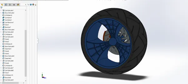
Features used in creating Rear Wheel are:
- Revolve: Revolve is used to create the sketch in a revolve manner at some angle.
- Boss Extrude: Boss extrude is used to convert a 2D sketch into 3D model.
- Circular Pattern: Circular pattern is used to create a pattern of rims that is to duplicate the rims for 3 instances about a point and along an angle.
- Combine: This feature is used to merge two bodies
- Cut Revolve: This feature is used to removed the extra body in a revolved manner.
- Fillet: This feature is used to smoothen the edges/corners in circular form.
- Chamfer: This feature is used to cut the corner/edge at sharp angle/distance
FRONT FORK
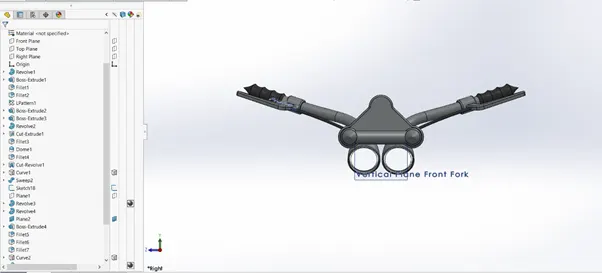
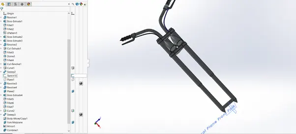
Front fork is the part of the bike that is used to hold front wheel.
The features used to design Front Fork are:
- Revolve: Revolve is used to create the sketch in a revolve manner at some angle.
- Boss Extrude: Boss extrude is used to convert a 2D sketch into 3D model.
- Fillet: This feature is used to smoothen the edges/corners in circular form
- Pattern: This feature is used to duplicate the instances at many numbers of time at a distance/angle.
- Dome: This feature is used to make the exterior surface of the body in the circular or elliptical form from outside.
- Sweep: This feature is used to create a 3D model using a sketch and a guide curve.
- Mirror: This feature is used to duplicate the features/ bodies along a particular plane/face.
- Combine This feature is used to merge two solid bodies.
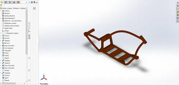
CHASSIS
Chassis is the base of Bike through which all the components of bike such as Fuel Tank, Wheel, Suspension, Seats etc are attached to it.
The features used to make Chassis are
- Sweep
- Mirror
- Boss Extrude
- Cut Extrude
- Chamfer
- Dome
- Split
- Revolve
- Mirror
ENGINE
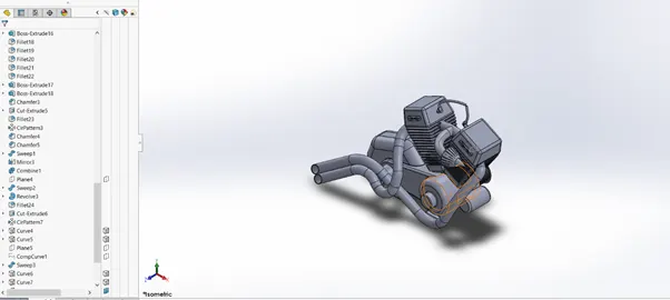
Engine is used to drive the power to the bike. The engine consists of a piston, cylindrical block, head. The piston moves up and down and is then driven by the explosion of fuel air mixture ignited by the spark plug.
The features used in engine
- Boss Extrude
- Fillet
- Revolve
- Circular Pattern
- Chamfer
- Mirror
- Combine
- Sweep
- Split
GAS TANK
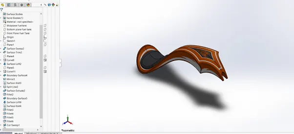
Features used in creating Gas Tank are
- Surface Sweep
- Surface Trim
- Surface Loft
- Surface Boundary
- Surface Knit
- Split
- Fillet
- Cut Sweep
- Shell
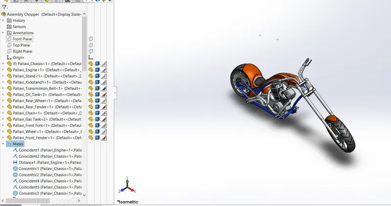
ASSEMBLY OF CHOPPER
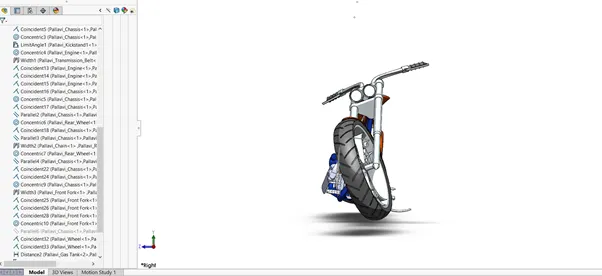
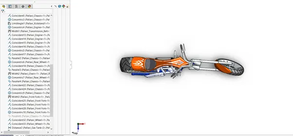
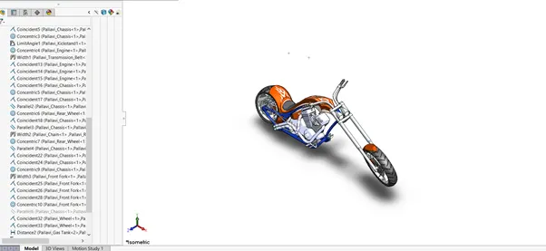
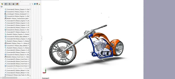
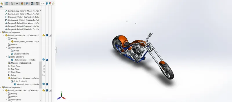
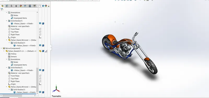
The various created parts are assembled to create the final model of Chopper.
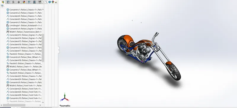
The mates used for assembly of Chopper are:
- Coincident
- Concentric
- Limit Angle
- Parallel
- Distance
- Width
- Tangent
RENDERING
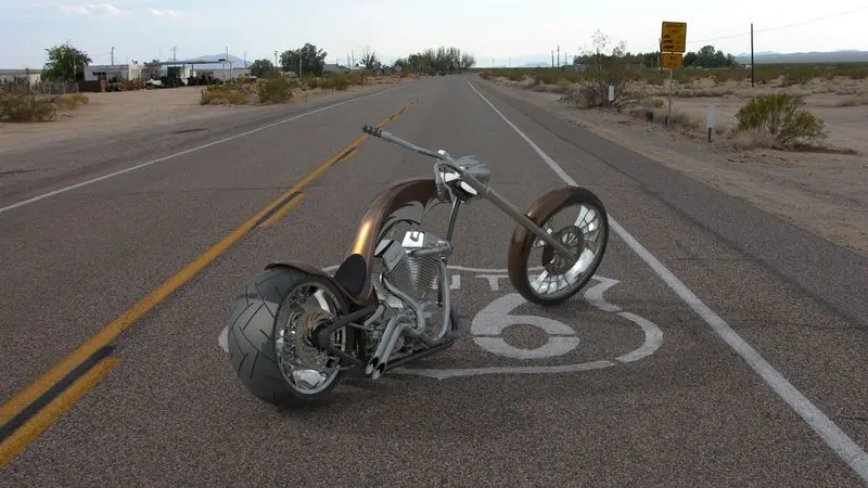
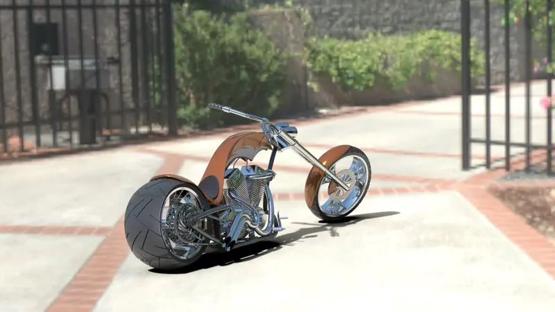
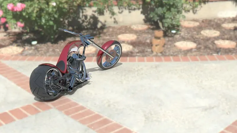
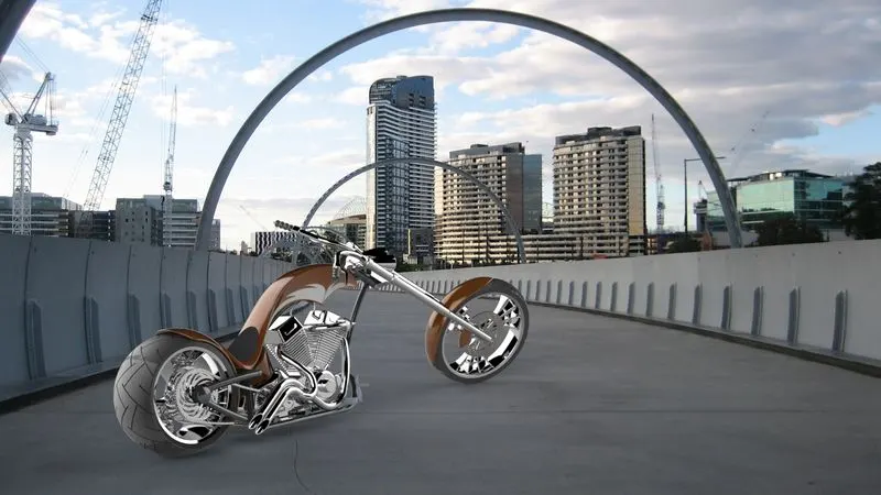
Rendering in solidworks photo view 360 and solidworks visualize is done to make the the and model as realistic as possible.
Below are some of the attached rendered images which has been rendered in solidworks visualize