Advanced Sheet Metal Design Using NX Cad Challenge_2_Box Assembly
TITLE OF THE PROJECT
To design box assembly using sheet metal in NX CAD software.
OBJECTIVE
- The main objective of this project is to learn box assembly
- To learn the fundamentals and advance tools of NX CAD
- To learn about various parameters and sheet metal designing.
INTRODUCTION
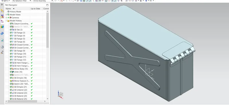
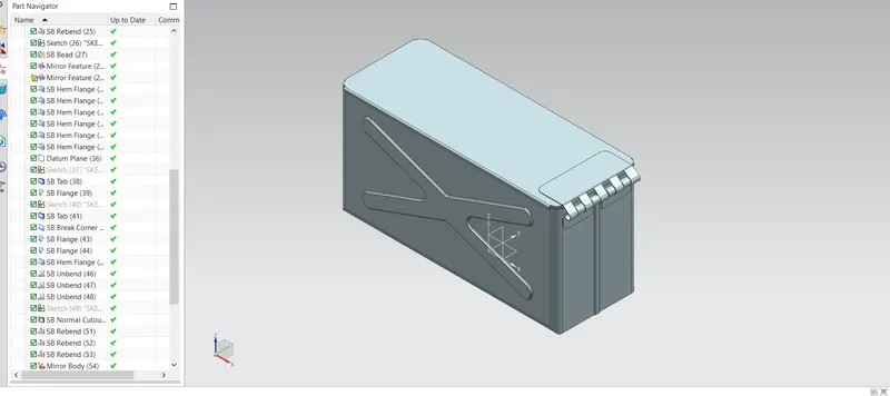
In this, we have to design a BOX ASSEMBLY using sheet metal. First of all the sketches are drawn and then those sketches are converted into sheets with the help of various tools and according to the requirements. After that the sheets are folded and bend using various tools to create a box then the side supports are designed with the help of various tools.
The tools and features used to create box assembly are:
- Tab
- Flange
- Closed corner
- Hem Flange
- Mirror
- Unite
- Dimple
- Unbend
- Rebend
- Bead
- Break Corner
DESIGN METHODOLOGY AND DESCRIPTION
WORKFLOW:
- Base sheet creation using tab
- Shaping in box by bending the sheet using flange
- Shaping of the corner Edges
- Duplicating all the features using mirror feature
- Creating a cross section dimple structure at two adjacent faces
- Creating the top cover
- Creaking the side supports in the form of side hooks.
DESIGNING:
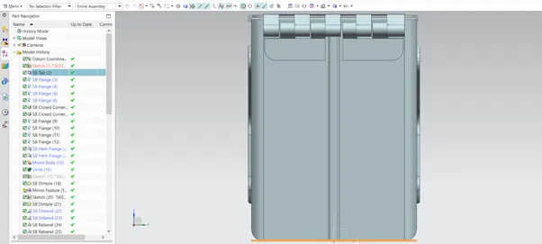
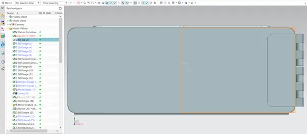
- To design the box assembly, we first created a thin sheet using tab by creating a sketch then it is bend using flange feature to create a box type structure
- TAB: Tab feature is used to create a extrude a sketch to a given thickness, it is also used to add some extra material on the existing tab.
- FLANGE: This feature is used to create a bend of edges at an angle and upto a given length.
- After that , the 2 corners which were remained open while bending, now both of them are closed using close corner feature
- After that, a flange is created in the inside for proper shaping at both the end edges of the box
- Closed Corner: This feature is used to close the corners where two tangent flanges meet.
- Then those corners are round using hem flange feature
- HEM Flange: It modifies the model by folding the edge of the sheet metal flange for the purpose of safe handling.
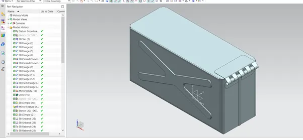
- The same feature that is created at the other side of the face using mirrored and duplicated to the other side.
- Mirror Feature:
- The mirrored feature is joined using unite feature command.
- Unite: This feature is used to join 2 bodies and make it to one.
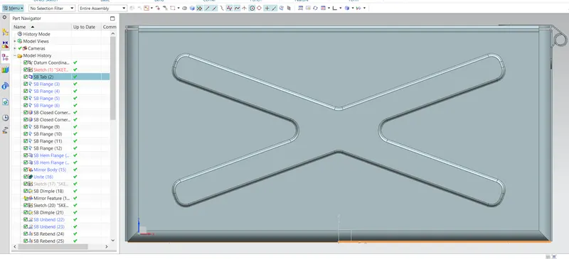
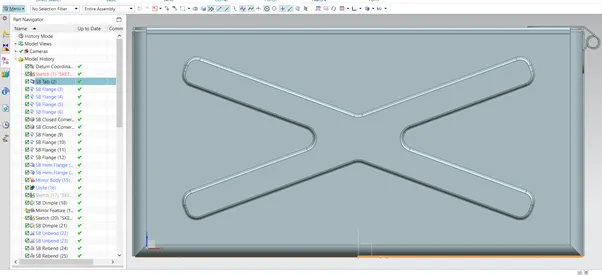
- After that, a cross Dimple is created at the adjacent face of the box and this feature is duplicated to the other side of the box using the mirror feature command.
- A slot dimple is created at the bottom side of the box
- Dimple: This feature is used to lift an area of the model inside a sketch. This can be closed or open. In this case a closed feature is used to bend.
- Then a circle is created in the same base face of the box and its lifted using bead feature after unbending the bent face of the box and the feature is duplicated to 4 using the mirror feature command. After that its rebend again
- Unbend: This feature is used to unbend the bended pieces of sheets
- Rebend: This feature is used to bend the unbend edges again.
- BEAD: It lifts the sketch along the contour of the sketch. It is used to provide the strength to the body
- The corner edges of the top have been bent in circular using hem flange feature.
- After that a datum plane is created at some distance along the top side of the box.
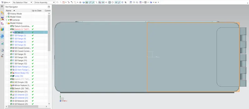
- A sketch is created to cover the top face with reference to the present structure of top and then it is converted to sheet using tab feature.
- The support is created at one of the edges of newly created tab using flange feature.
- A small tab is created at the adjacent smaller face and its one corner is break using corner break feature.
- Corner Break: This feature is used to break the sharp edges of the corners with the help of various shapes. In this case the corners are breaked using the circular blend of given radius. All the corners are breaked out.
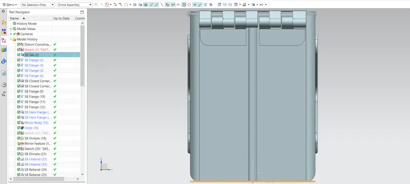
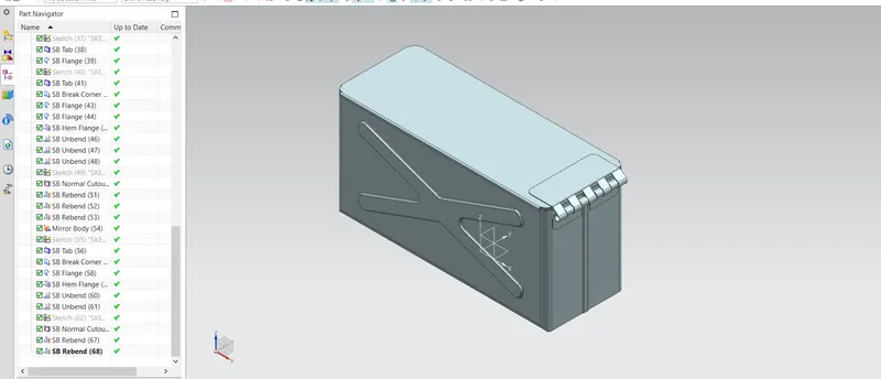
- Finally, the support hooks are created using Hem flange, Flange, Unbend, Rebend and normal cut out feature.
- HEM Flange: It modifies the model by folding the edge of the sheet metal flange for the purpose of safe handling.
- Unbend: This feature is used to unbend the bended pieces of sheets
- Rebend: This feature is used to bend the unbend edges again
- Normal Cutout: This feature is used to remove the material from given sheet and with the help of the given sketch
- The supports that are created in the previous step are copied to the same face using mirror feature command.
CONCLUSION
In this challenge, I have learnt about various types of commands of NX sheet metal by designing the box assembly. The various new commands have been introduced while making this challenge such as Hem Flange, Unite, Closed Corner etc.