Advanced Sheet Metal Design Using NX Cad Challenge_7_ Metal bracket-II
TITLE - MODELLING OF SHEET METAL BRACKET-Ⅱ
OBJECTIVE
To create the sheet metal bracket-Ⅱ using NX cad.
INTRODUCTION
Sheet metal tools are used to generate accurate flat pattern data for downstream applications from solids, sheets and wireframe geometry. NX offers high-performance modelling, drafting and assembly simultaneously. It Creates sheet metal component models using specific, feature-based tools for tabs, flanges and other necessary features. Sheet metal tools can be used to generate accurate flat pattern data and good finish.
DESIGN METHODOLOGY
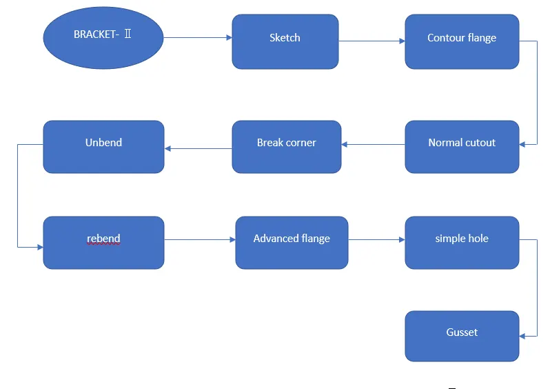
DESCRIPTION OF TOOLS AND FEATURES THAT ARE USED WHILE CREATING BRACKET-Ⅱ
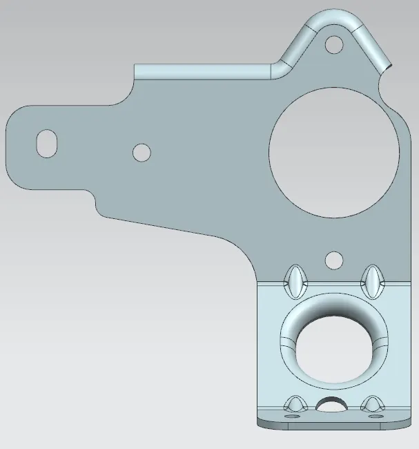
Bracket-Ⅱ
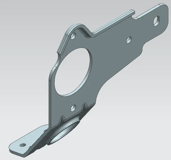
Features used to create bracket-Ⅱ
- Sketch
- Contour flange
- Normal cutout
- Break flange
- Unbend
- Rebend
- Advanced flange
- Simple hole
- Gusset
Sketch - It is a 2D representation of the part with respect to plane.
Contour flange - It creates a base feature by by extruding a sketch along the vector, or adds material by sweeping a sketch along an edge or chain of edges.
Normal cutout - It is used to remove a material of the selected sketch.
Break corner - It is used to create a round fillet or chamfer to the sharp edge to form a smooth finish.
Unbend - It flattens all the bends and made adjacent to the selected stationary face or edge.
Rebend - It is used to restore the unbend feature to its previous bend state.
Advanced flange - It adds a flange along an edge using a bend angle or reference face. The edge and reference face can be curved.
Simple hole - It is used to produce one or more holes to the solid material in a part.
Gusset - It creates stiffening gusset, it is used to build the strength on the part.
Flat pattern - It is used to create a flat pattern of the final obtained sheet metal part.
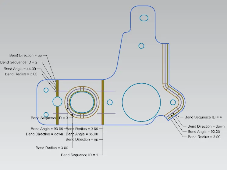
Process to create a bracket-Ⅱ
- Open the new sheet metal part file in NX cad and create a new sketch on YZ plane.
- Create another sketch on XZ plane and apply contour flange along that sketch.
- Apply normal cutout feature to remove the material as our requirement and apply break corner to the sharp edges to make it round fillet.
- Apply unbend feature to the part and create a sketch on the sheet metal part and remove the material along the sketch using a normal cutout.
- Rebend the sheet metal back to its previous state and apply few more break corner to the edges.
- Then apply advanced flange to the top edge and unbend the part again.
- Now create a few holes on the sheet metal part and apply normal cutout by creating a sketch, apply advanced flange to that sketch.
- Rebend the sheet metal back to its previous state and apply four gussets on the sheet metal to improve the strength of the part.
- Save the file as bracket-Ⅱ.
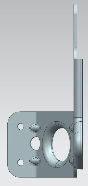
Bracket-Ⅱ
Front view
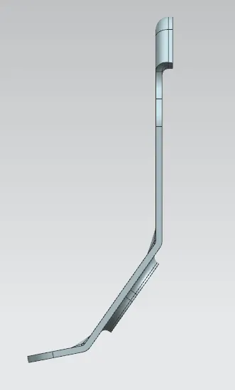
Side view
Isometric view
Top view
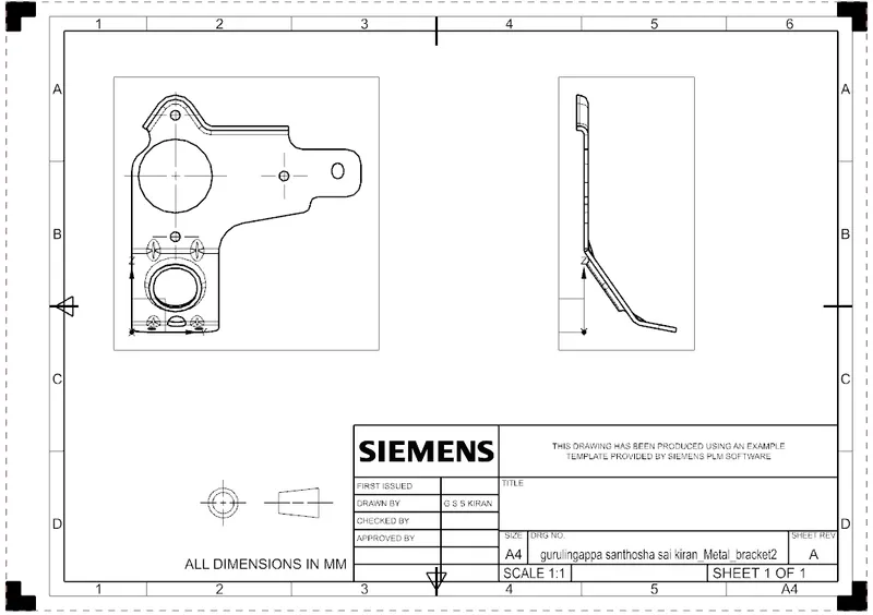
Drawing sheet
Conclusion
Thus the bracket-Ⅱis successfully designed using NX cad. The whole part is designed as per the guidelines with fully defined sketches.