Advanced Sheet Metal Design Using NX Cad Challenge_7_ Metal bracket-II
Metal Bracket using NX CAD
Objective:
The main objective of this project is to design the metal bracket from the given 2D drawing using the NX CAD sheet metal application workbench.
Introduction:
The bracket is designed in the given 2D drawing.
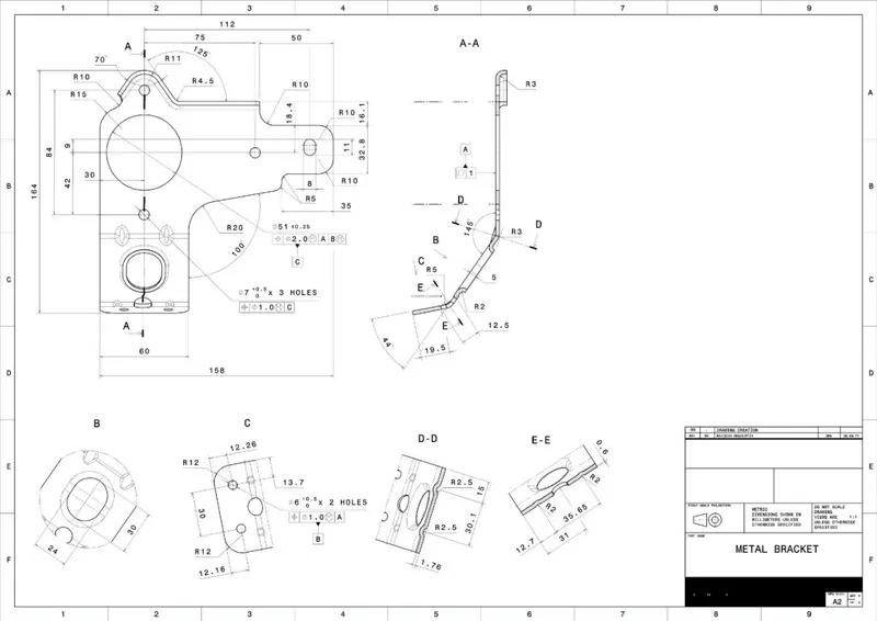
The basic feature of sheet metal like contour flanges, normal cut-out, unbend and rebend option are used.
Advanced feature like advance flange, gusset, hole is used.
To start with the design first we have to sketch the front side of the metal bracket from the given 2D drawing. Then the basic feature tab is created using the contour flange feature.
Contour Flange:
This command is used to create a base feature by extruding the sketch along a vector, or adds material by sweeping a sketch along an edges or chain of the edges.
Normal cut-out:
This command is used to cuts the material by projecting a sketch onto the model and then cutting perpendicular to the faces intersected by the projection.
Break Corner:
This command is used to create rounds or chamfers a sharp corner of a tab or flange.
Unbend & rebend:
Unbend command is used to flattens a bend and a material adjacent to the bend. rebend command is used to restores an unbend feature to its pervious bend state, along with and feature added after the unbend feature.
Advanced Flanges:
This command is used to adds a flange along an edge using bend angle or a reference face. The edge and reference face can be curved.
Gusset:
This command is used to create a stiffening gusset on the part. It is usually made to add strength for the sheet metal part.
Hole:
This command is used to create a hole one more solid bodies in part or assembly with option for countersunk, counterbored and threaded.
Design Methodology:
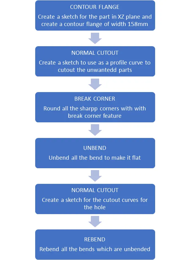
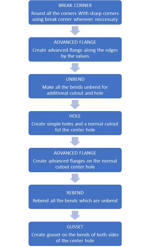
DESCRIPTION:
Sketch in the YZ plane:
In order to create a couple of normal cutouts in the bracket, the sketch is initially created keeping the profile accurately.
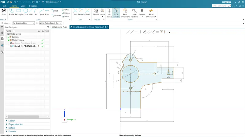
Sketch for contour flange in XZ plane:
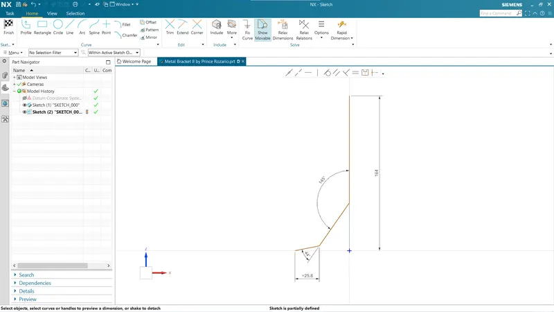
A contour flange can be created from any open curve. For this bracket, the sketch is created in an XZ plane with the following dimensions.
Contour Flange:
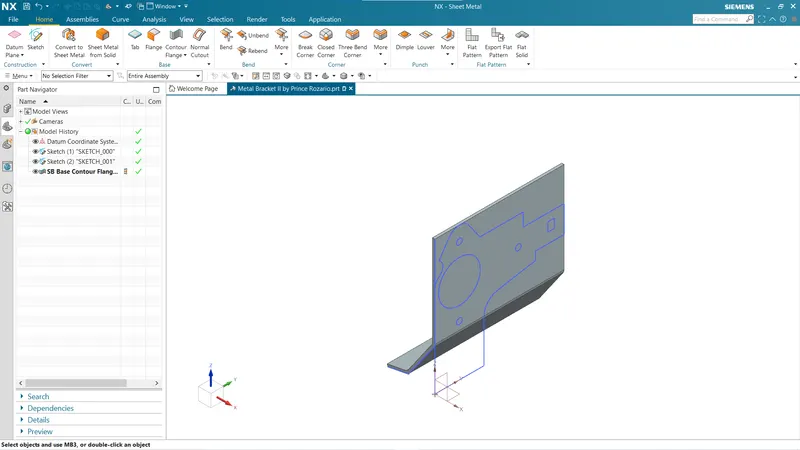
The contour flange is a flange created using the open sketch created in a plane. It is different from regular flange because it can be created in any shape and it does not require choosing the edge of any tab or existing flange. It can be at any position or at any angle. For this bracket design, a contour flange is created using the earlier sketch as the curve.
Normal cutout:
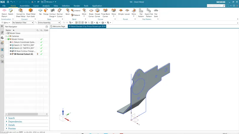
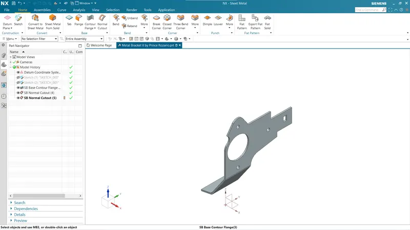
It cuts away the material at the right angle with respect to the sketch plane. A closed sketch is created on the YZ plane to cut away the unnecessary material. Sketch 1 is projected and the required closed contours are sketched wherever cuts required. Then the operation normal cutout is carried out.
Break corner:
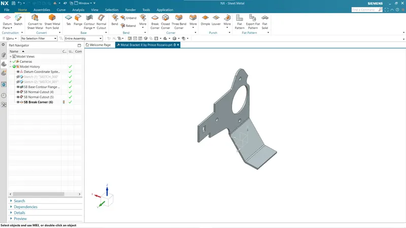
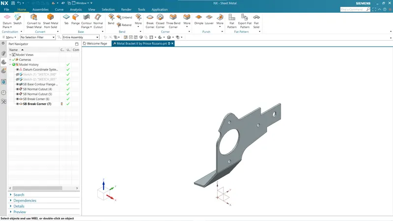
Break corner rounds off the sharp corner in the sheet metal part. It is just like a fillet feature in ither CAD software. It replaces the sharp end with round edges or faces making it smooth and reducing the chances of failure and stress concentrations at the sharp ends. In this bracket, break corner is used in several corners with an appropriate radius as shown below.
Unbend:
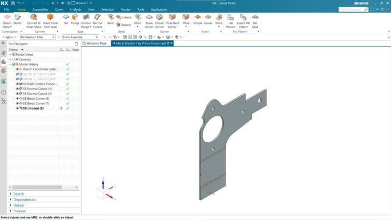
This is a very powerful and very useful tool in siemens NX. It’s allowed all the bends made by the various features to the unbend state at once. In order to achieve a flat configuration of the sheet metal as per the design intent, it is necessary to choose the bends in order. IT is also possible to box select all the bends at once. Once the unbend feature is used, future features can be carried out using the sketches created in the unbend state.
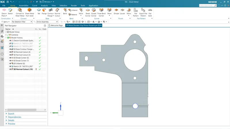
Normal cutout:
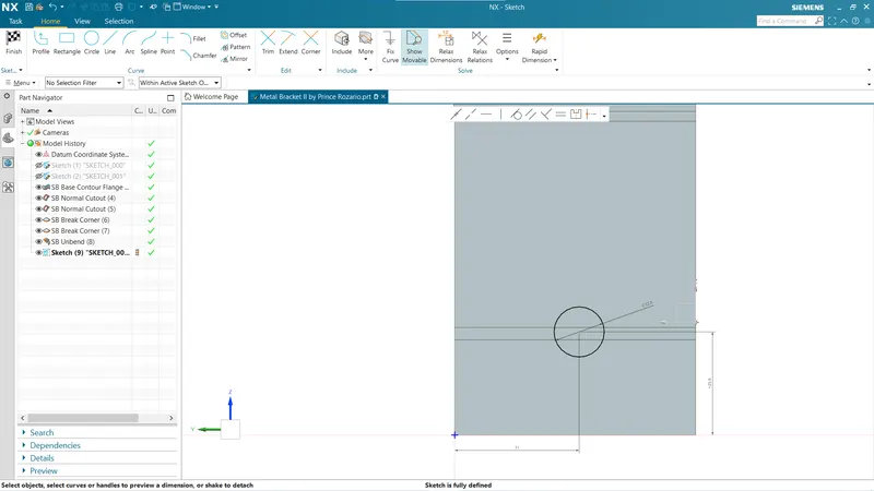
It cuts away the material at the right angle with respect to the sketch plane. A circle is created on the YZ plane in an unbend state. One of the important things to note in this step is that any hole or notch like opening should be at least three times the thickness bend radius away from the bend.
Rebend:
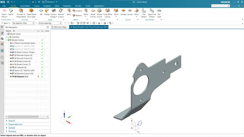
All the feature added after the unbend feature are added in the unbend state itself. After the addition of sketches and additional feature are completed, the sheet metal components have to be rebend to the required position. This is done using the rebend feature and selecting all the bends in order or box selection.
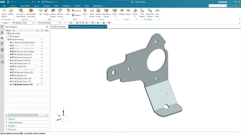
Break corner:
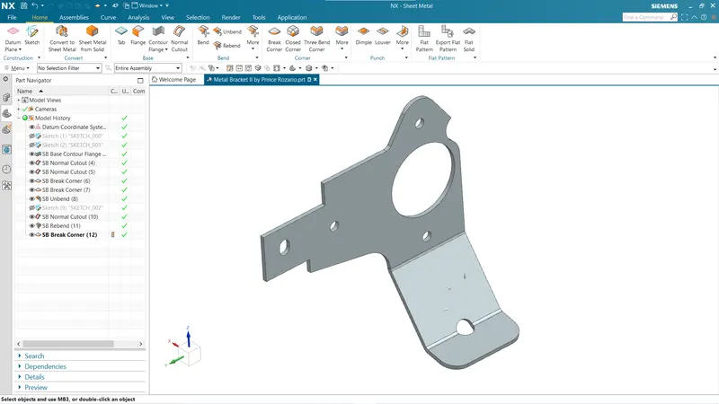
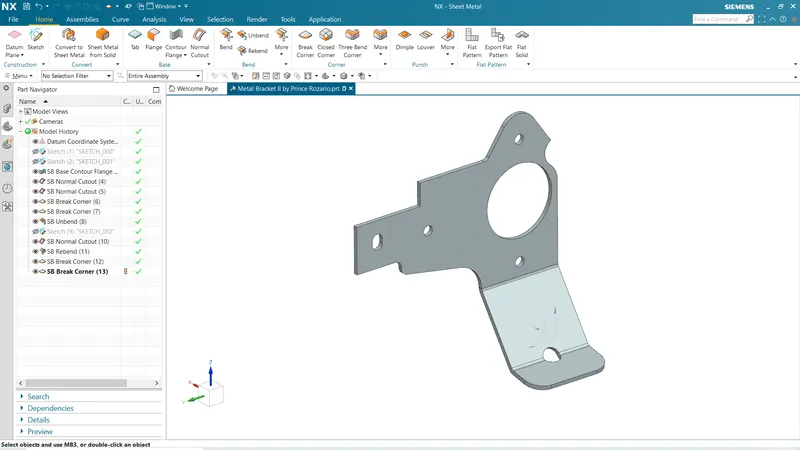
Again, the break corner is used in several corners with an appropriate radius as shown below.
Advanced flange:
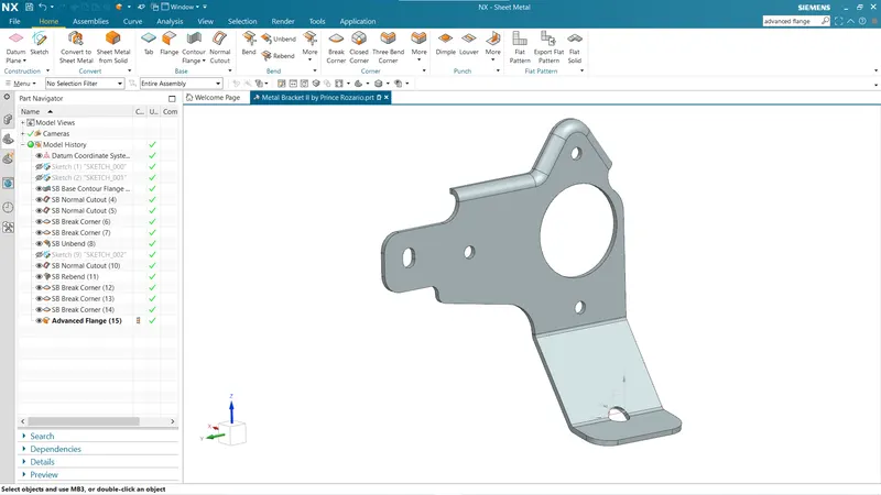
Unlike base simple base flange, the advanced flange can create flange from any edge which can be either curved or straight line, open or closed profile. This allows creating a flange with a match face also. For this bracket, the advanced flange is created at the upper portion with proper parameters as shown.
Unbend:
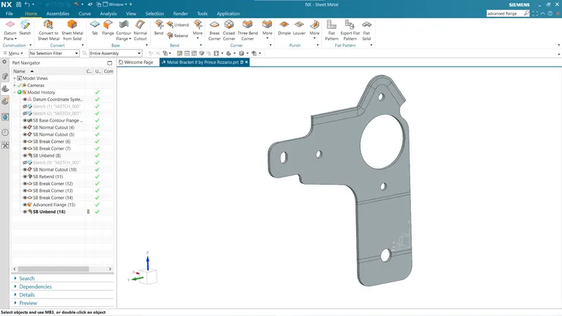
Again, the unbend feature is applied after which a couple of features are applied.
Hole:
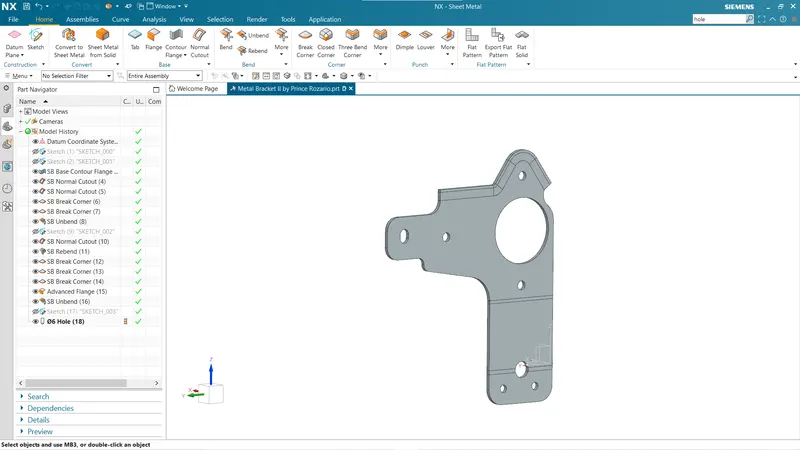
The hole feature in sheet metal is similar in solid modelling. Here, two general holes of 6mm radius are created while in the unbend state.
Normal cutout:
Again, a couple of normal cutout are carried out in the unbend state as shown below.
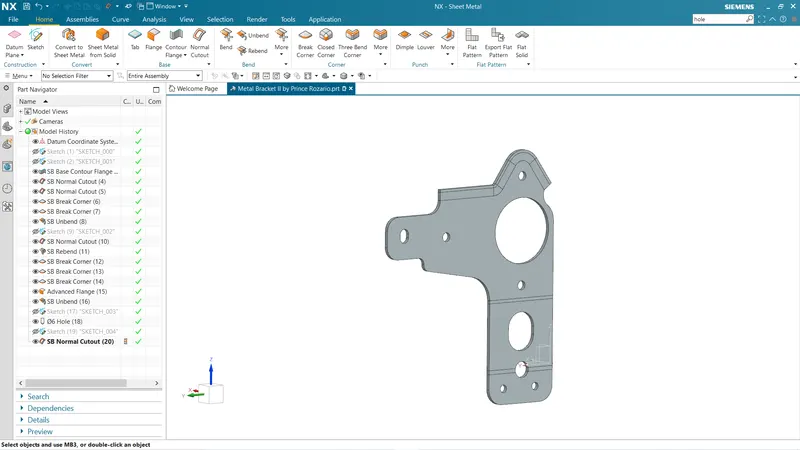
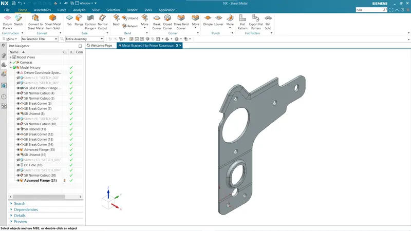
Advanced flange:
Again, an advanced flange is applied at the edge of the normal cutout created in the above step.
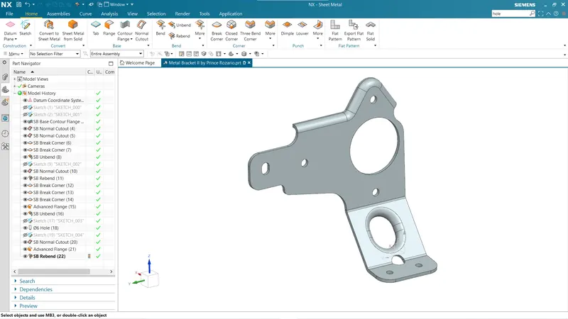
Rebend:
All the feature added after the unbend feature are added in the unbend state itself. After the addition of sketches and additional features are completed, the sheet metal component has to be rebend to the required position. This is done using the rebend feature and selecting all the bends in order or by box selection.
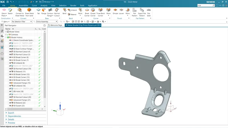
Gussets:
Gussets are basically supporting feature that provide the structure of the part of the product from the base tab or flange wherever the bend exists. These are stiffening feature applied at the bends. For this bracket, four rounded gussets are applied in the bends as shown below.
View of Model:
Front View:
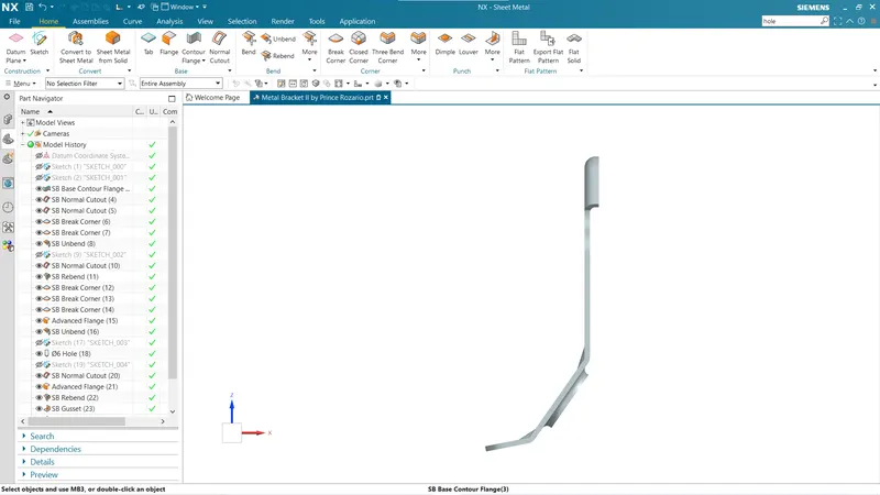
Top View:
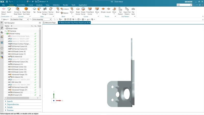
Side View:
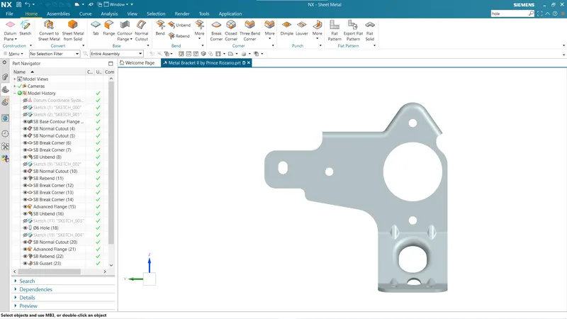
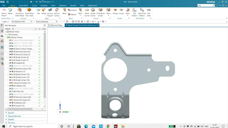
Isometric View:
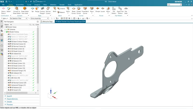
Conclusion:
In this project, a sheet metal bracket is successfully designed from a solid body in the sheet metal workbench of siemens NX. The advantage of a parametric modelling environment is used to maintain our desired design intent and all the necessary features are applied in order following the industrial workflow.