Advanced Sheet Metal Design Using NX Cad Challenge_1_Casing Design
Casing Design Using NX Cad
Objective:
The main objective of this project is to design a sheet metal casing in NX Cad sheet metal application workbench. Also perform the drafting for the casing part.
Introduction:
The sheet metal application provides an environment for the design sheet metal parts used in Machinery, Automotive and Aerospace, Enclosures, Brackets and other parts are normally manufactured with break press. The sheet metal applications are widely used in:
- Aircraft Bodies
- Automobiles
- Utensils used for domestic purpose
- Beverage can
In sheet metal application we can create a uniform thickness sheet metal parts using the basic features tab, flange and jogs. We can also do close corners, cutouts and stiffness features. The complex sheet metal parts can be designed in the solid model workbench and then we can convert it into sheet metal part. We can also import, clean up and convert a non-sheet metal parts into a valid sheet metal part. Flat Pattern sheet metal data can be used for the manufacturing process. The material parameters such as thickness, bend radii and bend relief can be easily set as default settings.
Design methodology:
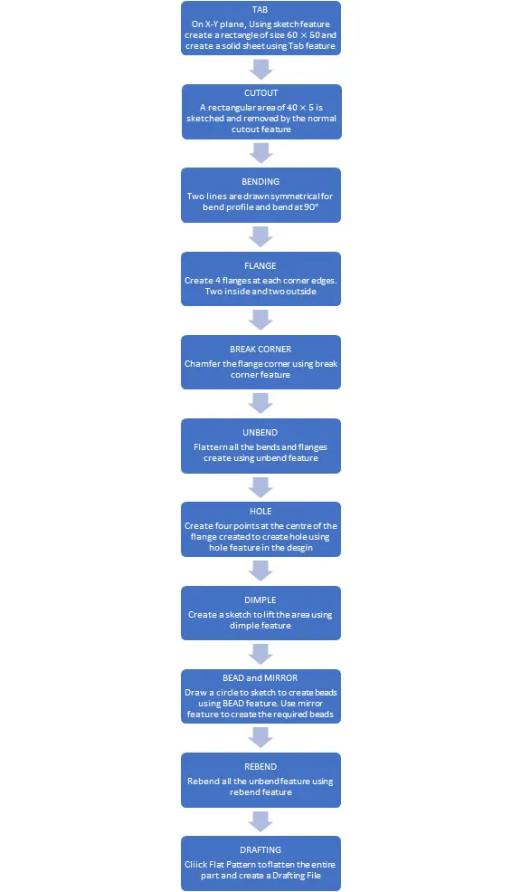
Description:
The sheet metal casing has been done with the above flow chart process. While designing the default thickness, bend radius, relief depth and relief width value are set to 1mm.
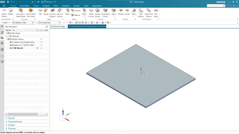
The sketch is drawn in the XY plane and the tab command is used for creating the base of the part.
Tab:
It is a base feature for any sheet metal component. This creates a metal shape by adding material to it or by extruding base sketch along a vector. All further features are modelled considering Tab as parent hence having a smooth flow to design. For creation of tab, we first draw a sketch profile of tab, NX allows to have both commands in single command to go there by saving time. Also, we can make this sketch as external as required.
Normal Cutout:
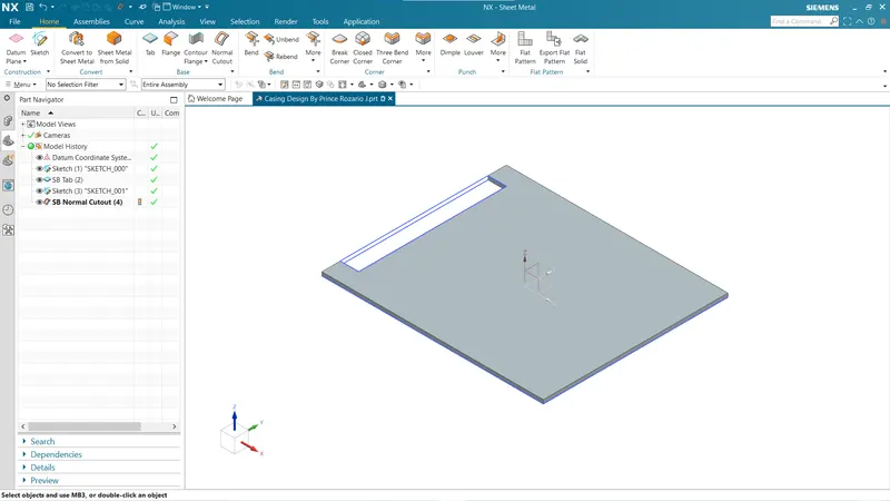
This feature helps to cut or remove material by projecting a sketch into the model and then cutting perpendicular to the faces. In the design of casing, we used a rectangular sketch and applied normal cutout with reference to it. We can specify the sketches or 3D curves to apply normal cutout.
Bend:
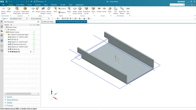
This feature is used to bend surface of sheet with respect to sketch. In sheet metal working we required many times to bend to have a useful product. In design of casing, we required to bend sheet about to axis which are symmetric and parallel to each other.
Flange:
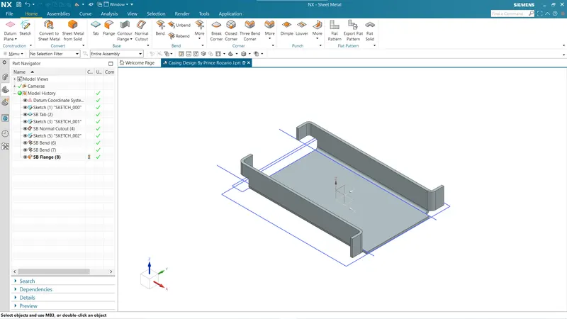
This feature is used to add a flat flange at angle to planar face and add a bend between two. A flange consists of a bend region and a web. In design of casing, we created four flanges at 90 deg to the pervious bend surface. To create flange using this it is required to specify edge.
Break Corner:
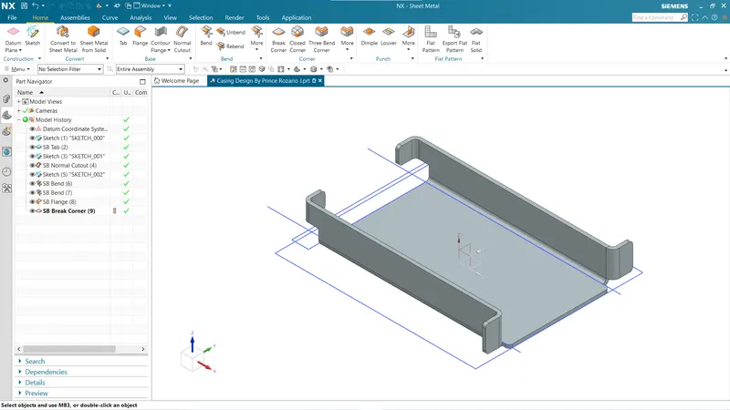
This feature breaks sharp edges to smooth round shape or chamfer shape. Create this feature over sheet give smooth shape and avoid any fracture.
Unbend:
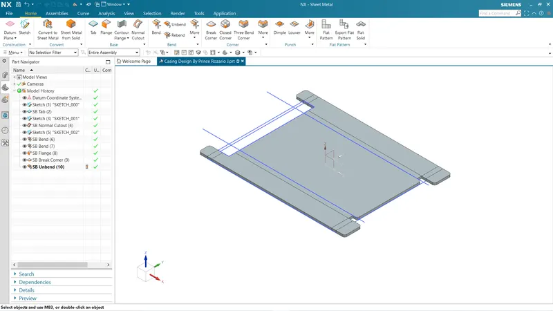
This feature is used to unbend the previous bended shape. In sheet metal design every extra feature like hole need to created over flat configuration so that the feature applied will be normal to the flat surface. To apply unbend command in order to have flat configuration we must perform it in proper order. A flat surface is the input to this unbend command with respect to it bended sheet will be un-bended.
Hole:
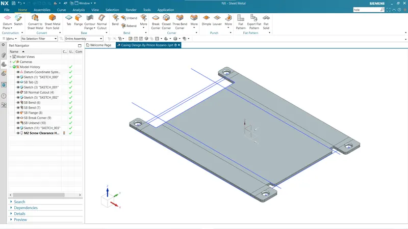
To cut or remove material in hole shape like counterbore, countersink, through hole, tapered this feature is used. Rather than just removing material it also creates metric threads in various standards like M1, M2, M3….M52. To apply hole in sheet metal we required to specify point which will be center for hole. In casing design, we formed four holes on flat flange.
Dimple:
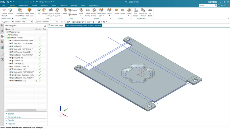
This command lifts the area of model inside sketch that stimulates a stamping tool. Tis is an extra feature that provides over sheet to increase the strength and rigidity if the components. To apply dimple in NX we must specify the sketch profile that to dimple. In design of casing, we used 16-point profile to form the dimple in center of tab having 1mm depth.
Beads:
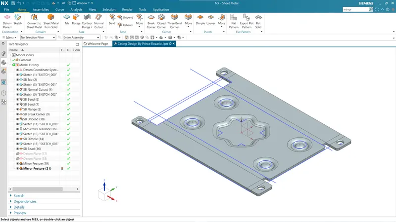
This feature lifts the material along the contour of sketch that stimulates stamping tool. Beads are created to stiffen or strengthen the material of component. In order to apply beads a sketch profile is needed which could be an open or closed one. In design of casing four circular beads are created with 1mm as depth and radius in symmetric pattern.
Re-bend:
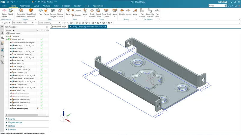
This command re-bend previously un-bended sheet to have a component is done in order as it was un-bended with reference to flat tab. In design of casing this is a last operation to get proper casing as required.
Flat Pattern:
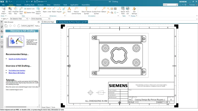
It is the entire represented of sheet metal component in 2D form. This flat pattern shows entire feature that are performed over sheet like bends, cutout, holes, dimples, beads in form of line drawing.
Drafting:
It is referring to creating technical drawing that communicate about dimensions, view of component geometry and other feature that performed over part 2D or 3D. The draft of drawing is prepared which include annotation, dimensions, relations etc. which helps to a person in manufacturing or production department about component. We made a drafting of flat pattern of casing on A4 Sheet in 2:3 scale format.
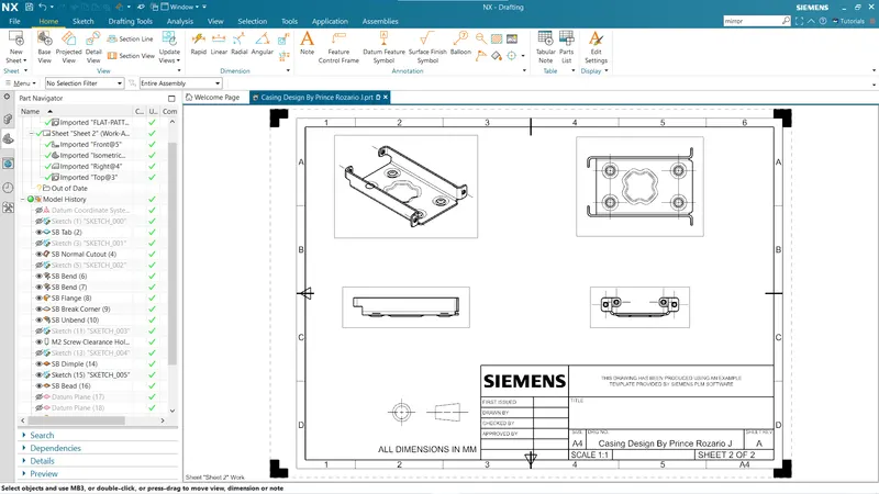
Different Views of Sheet Metal Casing:
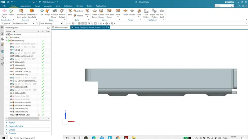
1.Front View:
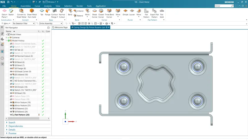
2.Top View:
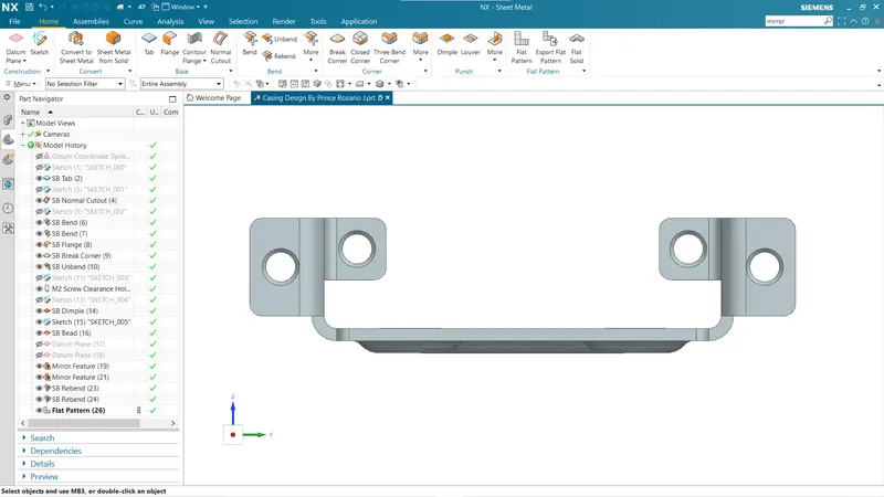
3.Side View:
4.Isometric View:
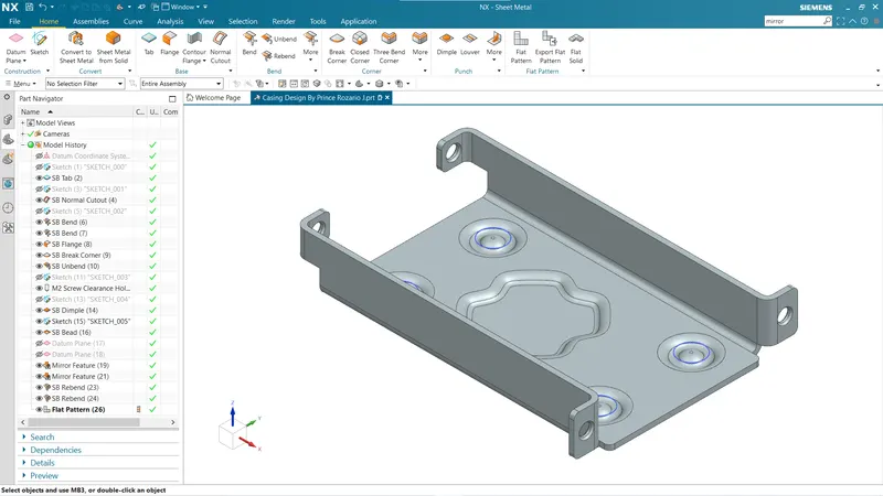
Conclusion:
Finally, with this project on Sheet Metal Casing in NX Cad basic understanding about NX GUI and its Sheet Metal Application developed. Also this project taught about basic approach to sheet metal modelling and utilization of basic commands.