Advanced Sheet Metal Design Using NX Cad Challenge_2_Box Assembly
Box Assembly Using NX Cad
Objective:
- The main objective of this project is creating a Box Assembly and learning the application of hem flange, normal cut-out in Sheet Metal design using NX Sheet Metal Application Workbench.
- Practice industrial approach of Sheet Metal Design.
Introduction:
In this challenge we have created the Box Assembly using various basic features like bend, flange, hem, break corner, dimple, mirror, unbend and rebend. The box assembly consists of a box, closure, the hinges between the closure and the box. Hemming operation is done for connecting two sheet metal, so that the box has the aesthetic looks and the perfect joint. None of the component in the assembly is having the sharp edge which could hurt the end user. Dimple operation is done on the two sides and the bottom of the box to ensure the stiffness and strength of the box. Beading is done on the bottom of the box which could act like a bush.
Design Methodology:
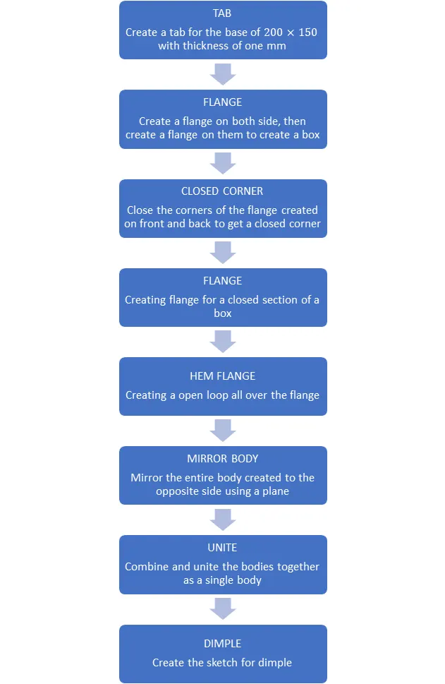
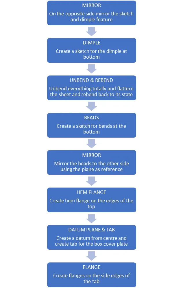
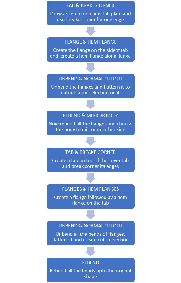
Description:
Step 1: Creating the Base sketch
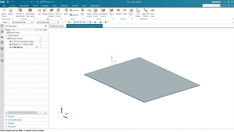
The first step is to crate the base sketch for the design and then the base sketch is converted to base tab which is nothing but providing the thickness for the sketch, so that we can add more feature from the bade tab.
Step 2: Adding Flanges to Base Tab
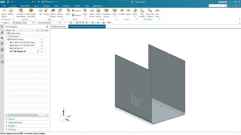
After crating the base tab, the flanges are added at the edges of the tab, so that the walls for the Box Assembly is created. Four flanges created in the XY and XZ plane with the required length and the bend radius of 10mm.
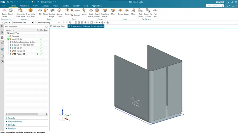
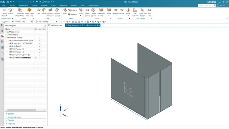
Closed corner option is used to close the gap at the bottom of the created flange.
Step 3: Adding supporting flanges for the Hemming operation
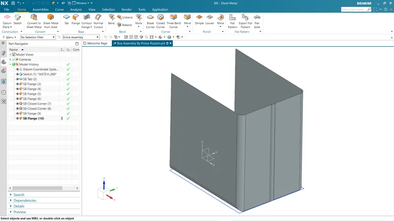
The supporting flanges were creating at the opening of the two flanges, so that we can easily perform the hemming operation to join the Sheetmetal.
Step 4: Hemming operation
Open Hem operation is done at the two supporting flanges to join the Sheetmetal rigidity. This gives the aesthetic looks for the assembly as well as perfect joining operation.
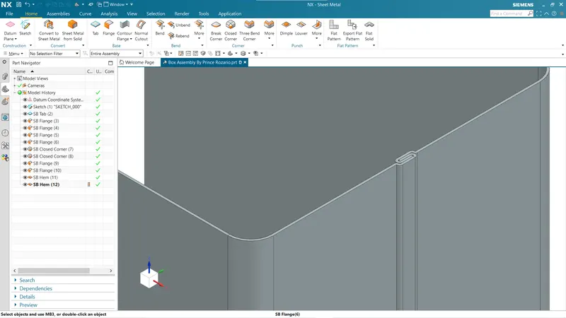
Step 5: Mirror Body and Unite
After the hemming operation, one half of the box assembly is ready. To get another half we have performed the mirror option so that the same half is reflecting without any error. This mirror option is done by selecting one half of the part and the mirror plane.
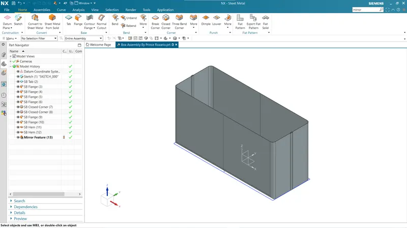
Unite option is done to combine the volume of the two bodies and make it as a single one.
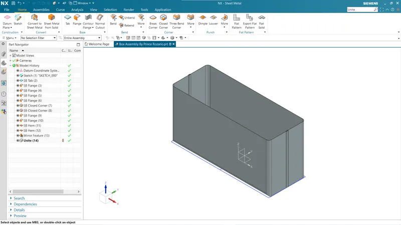
Step 6: Dimple and Mirror
Dimple operation is done at the side wall of the box assembly. This provides the extra strength and stiffness for the assembly. And the same feature is mirrored on the opposite wall of the box.
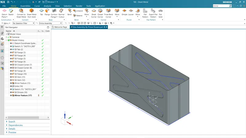
One more dimple is provided at the bottom of the box for the strengthen purpose.
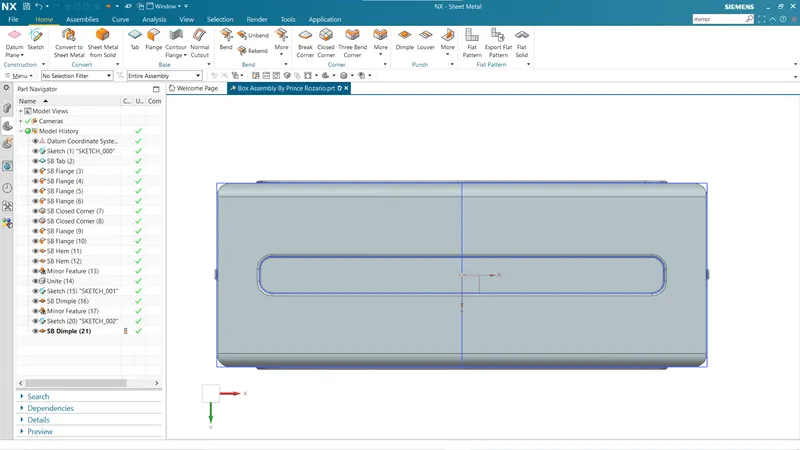
Step 7: Unbend and Rebend
After creating the feature, the Sheetmetal is unbend and rebend for checking the manufacturing feasibility of the added feature.
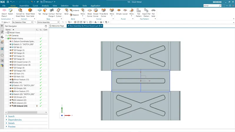
Step 8: Bead and Mirror
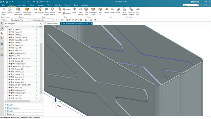
Bead is a long, drawn out impression, which is impressed to increase stiffness of metal sheet or plates. Depending on the workpiece size and material thickness, the ratio of length, width and imprint depth must be adjusted to obtain the maximum strengthen effect.
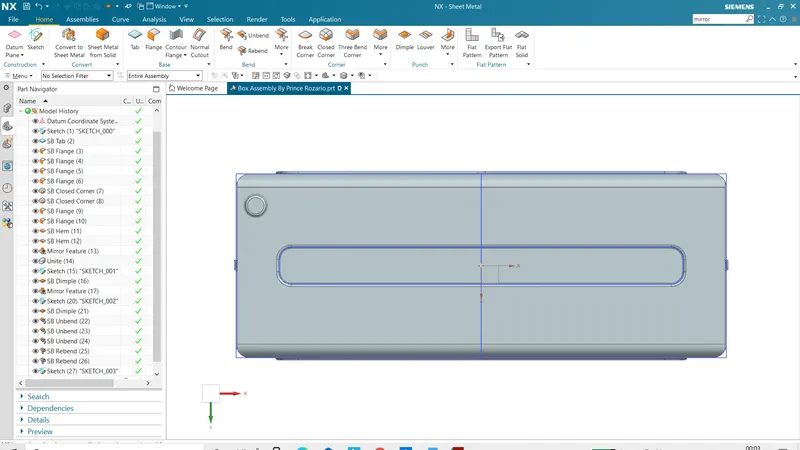
The same bead is mirrored for the four corners in the box assembly.
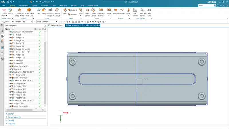
Step 9: Closed Hem
Closed Hem is provided at the opening end of the box assembly, thus providing the blend edges on the mouth of the box. This is one of the operations for providing safety for the users to handle the box easily.
Step 10: Box closure
For creating the box closure, new datum plane is created by offsetting upto the height of the box. Then the sketch is drawn for that closure profile and then the base tab is created with the thickness of 2mm.
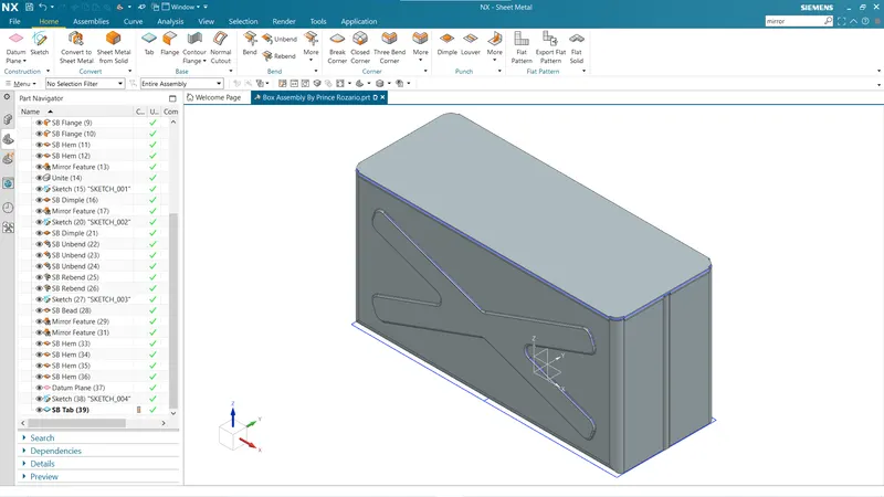
The edges of the closure are added with the flange feature in all the four sides.
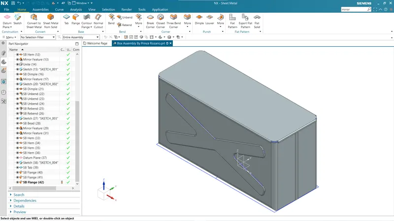
Step 11: Flanges for Hinges
Flanges were created at the certain angle to make the assembly for the closure and the box. This flange is then followed with the open loop hemming operation and the feature is mirrored.
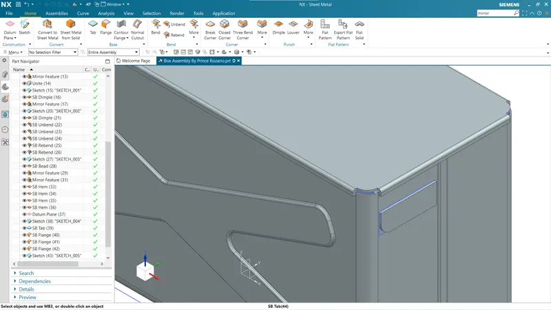
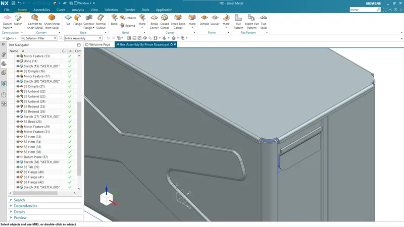
Step 12: Creating Hinges with Open Loop Hem
The open loop hemming operation is created with the sweep angle of 325 degree and bend radius 5mm. Then it is checked for unbend and rebend operation.
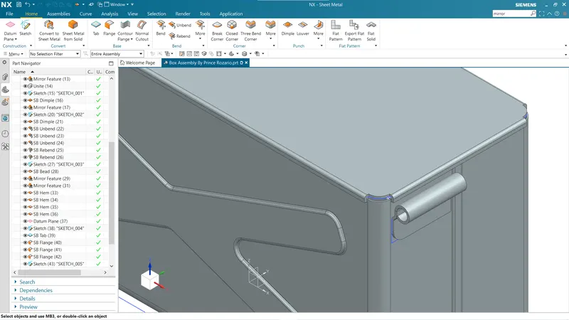
Step 13: Normal cut out
After unbending the flange then the rectangular profile sketch is drawn. Then normal cut operation is performed.
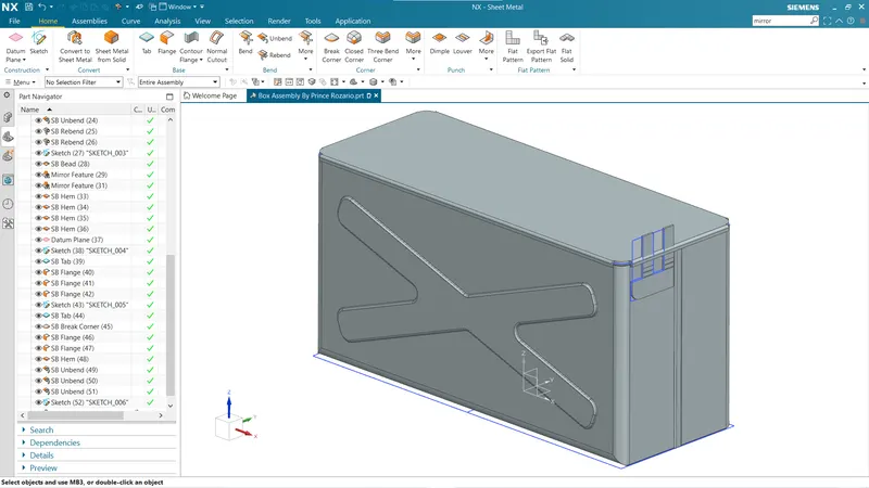
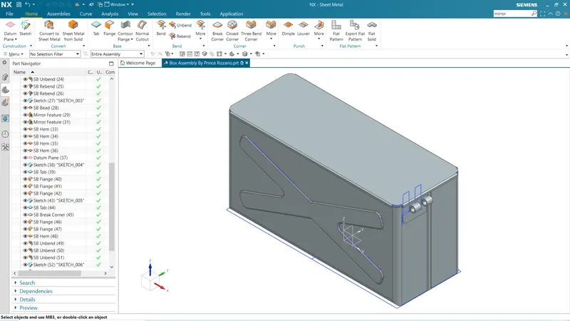
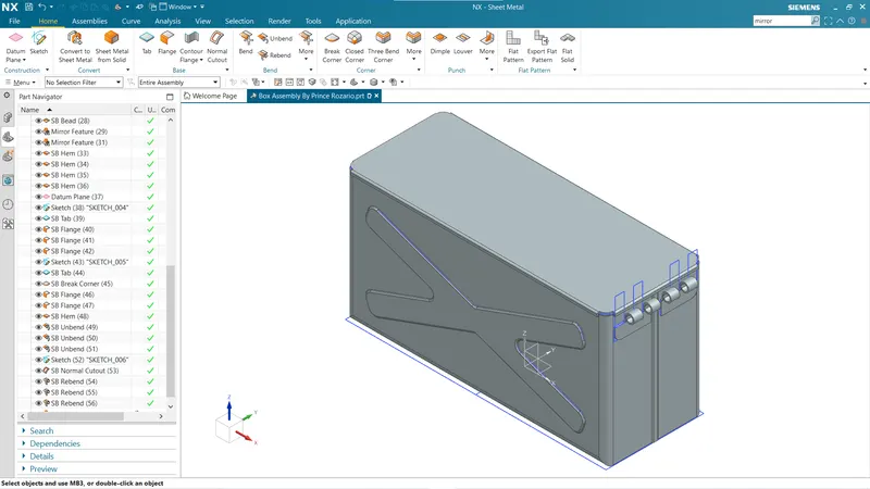
Step 14: Hinges in the Closure
The same above operation open hem and normal cut is performed for the hinges which is to be created in the closure also.
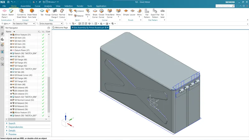
Step 15: Final hinge assembly
Thus, the final hinge assembly is done with the above process (flanges, open hem, normal cut out, unbend and rebend).
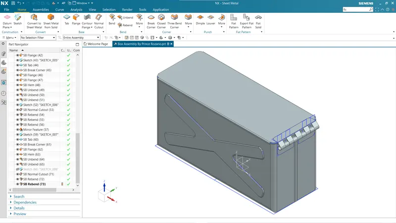
Drawing Sheet:
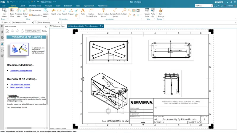
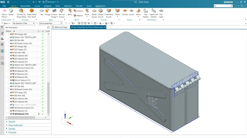
Different Views of Sheet Metal Casing:
1.Front View:
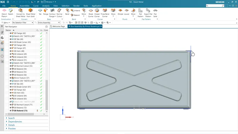
2.Top View:
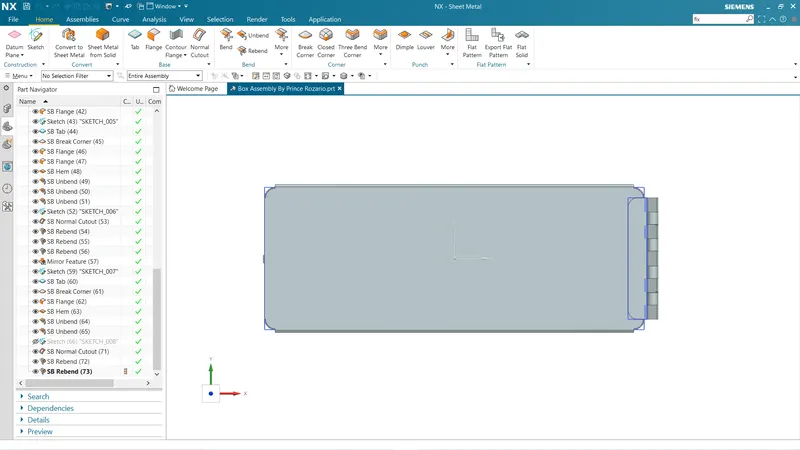
3.Side View:
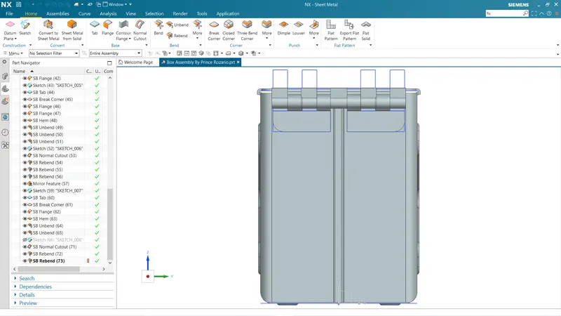
4.Isometric View:
Conclusion:
From the NX CAD by the tools and features of the Sheetmetal workbench like sketch, tab normal cut-out, closed corners, flanges, hem flanges, datum plane, mirror body, unite, dimple, unbend, rebend, bead, mirror feature, break corner etc we conclude the Box Assembly of Sheetmetal.