Assembly of Yacht
Design of Sunseeker Predator Yacht
Introduction:
This report contains a detailed explanation of designing a Sunseeker Predator Yacht starting from part modelling to final rendering of the assembly.
Objective:
The main objective of this project is to learn the basic knowledge about the surface modelling & assembly by using SOLIDWORKS and to create a photo-realistic view of the assembly by using SOLIDWORKS Photo View 360 & SOLIDWORKS Visualize.
The following steps are undertaken while designing the Sunseeker Predator Yacht:
- Modelling the parts of the Sunseeker Predator Yacht.
- Assembly of the Yacht.
- Give appropriate appearance to the part, lights and cameras.
- Final rendering of the assembly.
Solid Modelling:
Solid Modelling is generally to create a virtual prototype of an item. Consider a car engine it has hundreds of parts. Each part can be modelled separately and then assembled together to form an engine. This type of modelling is called as solid modelling.
Feature Description:
Sketch:
Sketch is the two dimensional representation of the model with respect to the plane/view from the outside of the model. In Solidworks there are different sketch options available to create a sketch. These are known as entities in solidworks. The following are the entities available in the solidworks line, arc, spline, circle and rectangle.
Extrude Boss/Base:
Extrude is a type of feature in solidworks to convert 2D sketch into 3D model.
Extrude Cut:
Extrude cut is another cool feature which helps to remove materials from the 3D model. It is just opposite to the Extrude boss/base feature, because it cuts the sketch profile while extruding. You can cut in the both directions and mainly used to make holes, channels and slots etc.
Revolve Boss/Base:
To create a revolve feature, create a sketch that contains one or more profiles and a centreline, line or edge to use as the axis around which the feature revolves.
Fillet:
Fillet/Round creates a rounded internal or external face of the part. You can fillet all the edges of a face, selected sets of faces, selected edges or edge loops.
Offset:
One or more sketch entities, selected model edges or model faces by a specific distance. For example, you can offset entities spline or arc, sets of model edges, loops and so on. You can also offset finite lines, arcs and splines.
Chamfer:
A cut on the corner or edge of something that makes it slope slightly rather than being a perfectly square.
Trim Entities:
Select the trim type based on the entity you want to trim or extend. All trim types are available in 2D sketches and 2D sketches on the 3D planes. You can use any of the following trim option such as power trim etc.
Dome:
Select one or more planer or non planer face. You can apply domes to faces whose centroid lies outside the face. This allows you to apply domes to irregular shaped contours.
Mirror:
Mirror is an important tool in solidworks. As you sketch the entities, they are mirrored about the selected sketch entity.
Split Line:
The split is tool is used to project an entity (sketch, solid, surface, face, plane and surface spline) onto the other surfaces or curved/planer faces. You are also able to split the faces on multiple bodies with one commend.
Shell:
The shell definition manager is used to define the thickness of thin and thick element.
Linear Pattern:
The linear parent bodies/feature are used to create a different number of instance are required to create the linear pattern.
Appearance:
An appearance defines the visual properties of a model, include colour and texture. Appearance does not affect the physical properties, which are defined by materials. Every material is assigned by a default appearance that emulates the look of the material.
Surface Modelling:
Surface modelling gives you the ability to build a visual representation of an objects exterior and its contours. In other words it’s a surface. Parts like seats, fuel tank of the chopper are surface modelled.
Feature Expansion:
Extruded Surface:
Using this feature, we can extrude the boundary edges of a face of a solid body or a surface body in a customized direction. A planar surface body is used to extrude its boundary edges.
Lofted Surface:
Lofted surfaces are surfaces generated by multiple 3D curves existing edges or creating a smooth tangency between the selected curves.
Swept Surface:
Swept surfaces are surfaces that are generated from a section curve position along a path.
Filled Surface:
The filled surface feature constructs a surface patch with any number or sides, within a boundary defined by existing model edges, sketches or curves including composite curves.
Surface Trim:
Primarily used to cut away material from surface, and provides two modes: standard and mutual.
Extended Surface:
Extended surface is used to extend the surface which is already created. There are different options available on the extended surface. We can extend the surface as same surface or we can extend surface tangent to the surface.
Ruled Surface:
This feature inserts a ruled surface from the selected edges.
Offset Surface:
Creates offset surface using one or more contiguous face.
Surface Knit:
Surface Knit is used to knit the two free edges/ open edges of the surface together. Also it reduces the gap between the two edges of the surfaces.
Methodology:
The predator yacht is made up of the following parts:
- Propeller
- Rader
- Hull
- Garage Door
- Front Seat
- Middle Seat
- Rear Seat
- Superstructure
- Rader Mask
1. Propeller:
A propeller is the key component of every marine vehicle and especially in the yacht since it has to gain high speed. It propels the vehicle forward using the pressure difference created by the blades of the propeller. The sketch profiles are created with provided dimensions and the features are applied. There are three instances of the propeller at the bottom of the Yacht.
Features: Revolving Boss/Base, Extruded cut, Lofted surface, Circular pattern and Fillet.
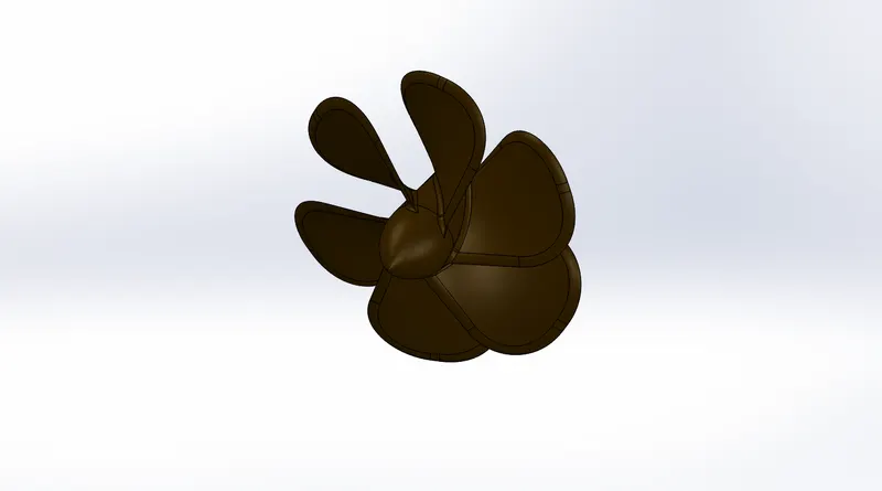
(a) Propeller
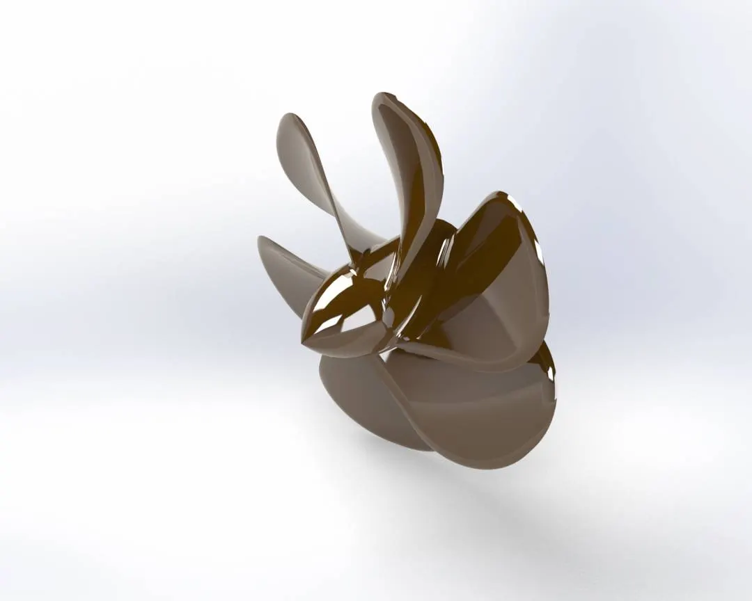
(b) Rendered Image of Propeller
2. Rader:
Rader is the component of the marine vehicles which scans and detects any objects and their position relative to its position. It is moveable along the axis of the mask. It is designed using simple extrude and fillet feature. Its hole is mated with the mask allowing the rotation.
Features: Extrude Boss/Base, Extrude cut, Sketch pattern, Mirror, Fillet and Split line.
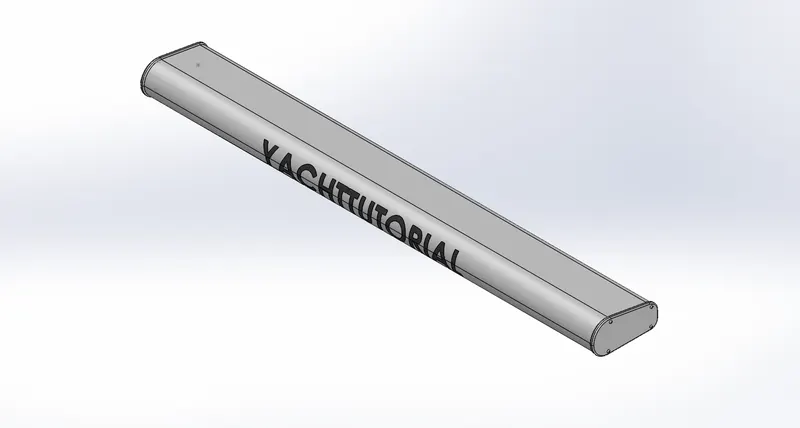
(a) Rader
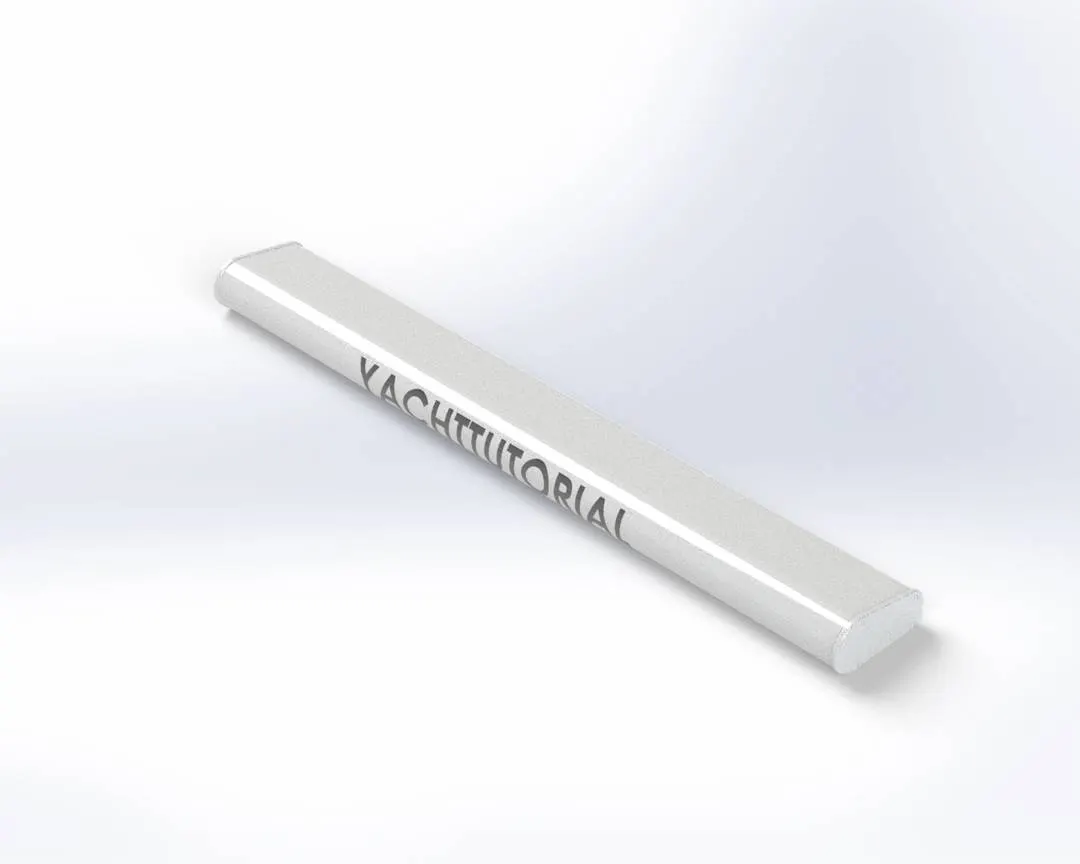
(b) Rendered Image of Rader
3. Hull:
Hull is the main part of the yacht. It is the giant component which extends 108ft long. It is the structure which holds all the other components of a marine vehicle. It is the part which enclosed and water-lift is created for the movement of the vehicle on the surface of the water. The curves as sketched as close to the blueprint from two different views and projected to form a 3D curve. 3D sketches are also used in this part. The hull from the yacht was created using the surfaces made out of the projected curve using the blueprint sketches. It consists of the parts like railings, bow, deck, pulpit, anchor, garage, window etc.
Features: Projected curves, Lofted surface, Trim surface, Filled surface, Knit surface, Shell, Extrude Boss/Base, Extrude cut, Swept Boss/Base, Linear pattern, Dome, Fillet and Chamfer.
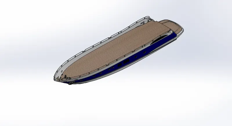
(a) Hull
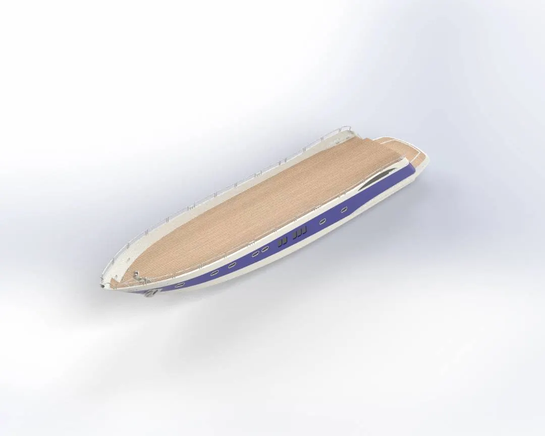
(b) Rendered Image of Hull
4. Garage Door:
The garage door was created out of the split block of the hull. It is provided with two holes to adjust the pins in order to open or close the garage door. It encloses the garage space which can accommodate a locomotive inside it.
Features: Extrude cut, Shell, Mirror and Fillet.
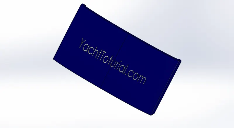
(a) Garage Door
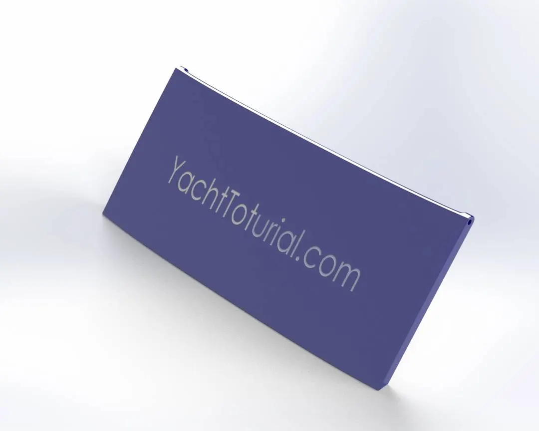
(b) Rendered Image of Garage Door
5. Front Seat:
The front seat is designed with reference to the deck surface and the blueprint. It is designed using surface features and also extrude feature. Dome is applied to the surface to imitate the cushions of the seat. A small water pool lies in the superstructure behind the front seat.
Features: Extruded surface, Lofted Surface, Swept Surface, Filled surface, Trim surface, Knit surface, Offset surface, Extrude Boss/Base, Revolve Boss/Bass, Dome, Chamfer and Fillet.
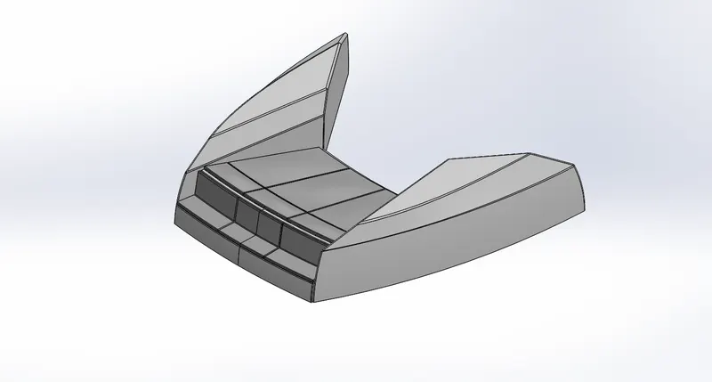
(a) Front Seat
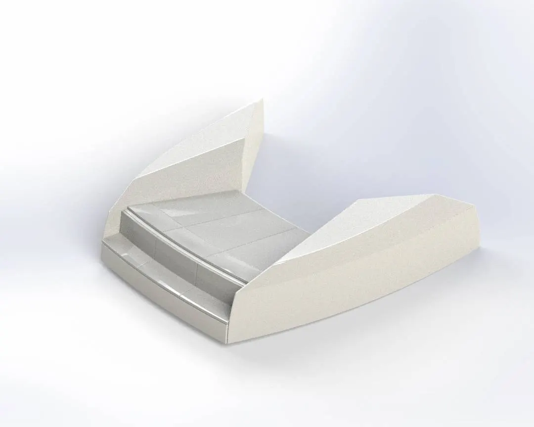
(b) Rendered Image of Front Seat
6. Middle Seat:
The middle seat is also designed with reference to the deck surface as the ground and the blueprint sketches are reference for the dimensions and views. This seat is U shaped seat with a table in the middle. It lies behind the superstructure of the yacht. This part design is done without involving surface design.
Features: Extruded Boss/Base, Extrude cut, Mirror, Chamfer and Fillet.
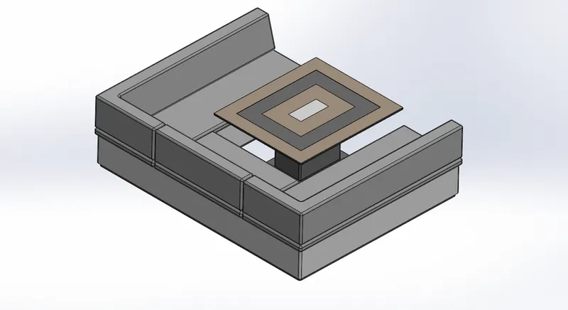
(a) Middle Seat
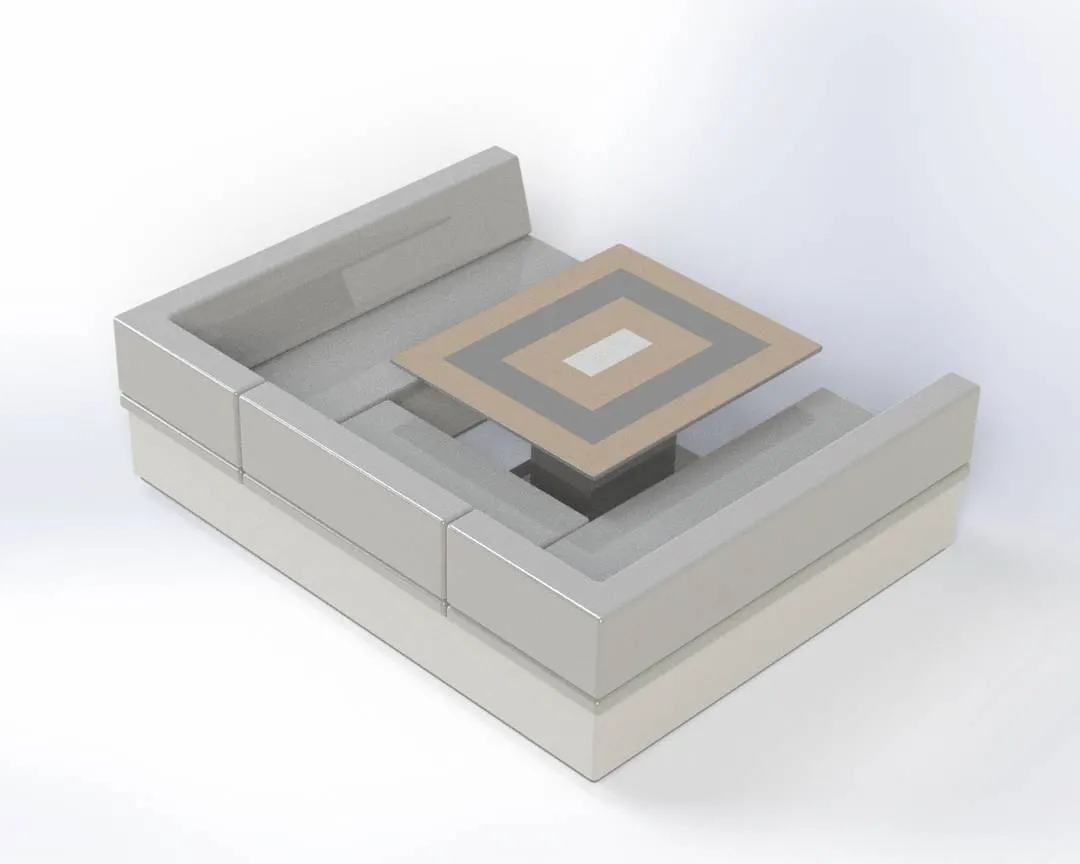
(b) Rendered Image of MIddle Seat
7. Rear Seat:
The middle seat is also designed with reference to the deck surface as the ground and the blueprint sketches are reference for the dimensions and views. Surface feature are employed more in this seat than in the others. It is also provided with the flag at the end which is designed as a surface to represent the natural look of a flag in wind. It lies at the back of the middle table and the end of the deck surface.
Features: Lofted surface, Swept surface, Extruded surface, Filled surface, Ruled surface, Surface trim, Knit surface, Extruded Boss/Base, Revolve Boss/Base, Mirror, Chamfer and Fillet.
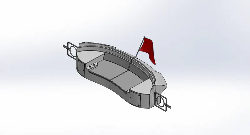
(a) Rear Seat
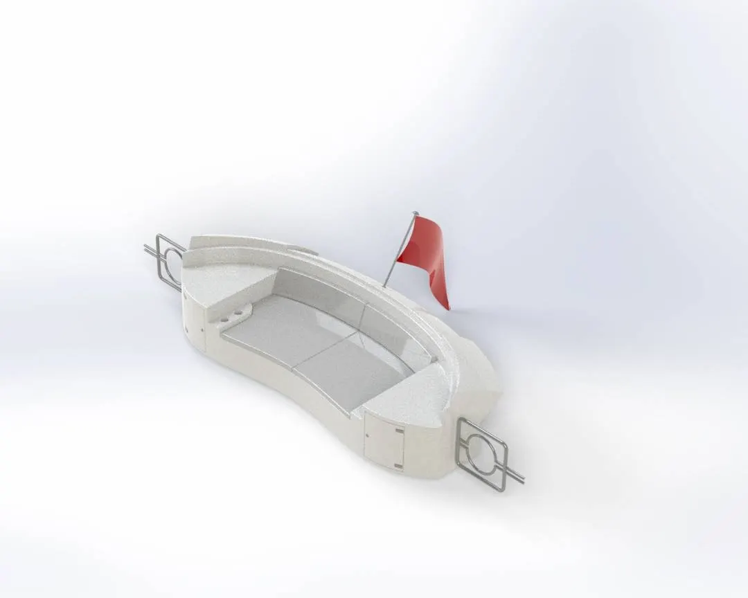
(b) Rendered Image of Rear Seat
8. Superstructure:
It is the part that sits on the deck surface of the yacht. In general, the superstructure consists of the cockpit, mask, table etc. For the modelling of the superstructure, the deck surface was used as the base so it directly inserted and fixed in position in the assembly. The curves as sketched as close to the blueprints from two different views and projected curves to form a 3D curve. 3D sketches are also used in this part. Windows and the windscreen wipers are also included in this part. Back doors and the windows are provided with the dark coloured glass.
Features: Lofted surface, Swept surface, Extruded surface, Filled surface, Ruled surface, Surface trim, Knit surface, Offset surface, Extruded Boss/Base, Extruded cut, Mirror, Chamfer and Fillet.
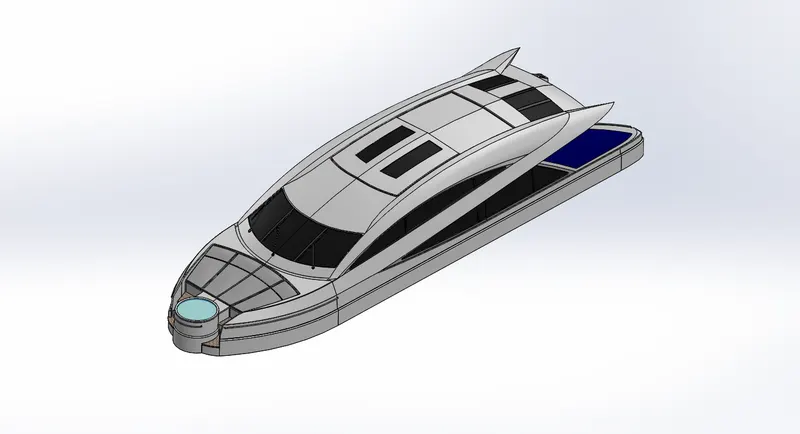
(a) Superstructure
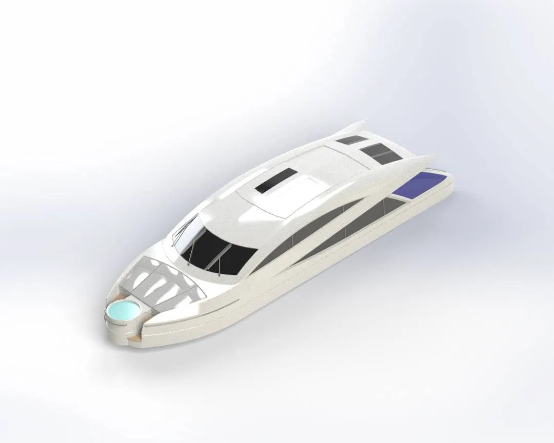
(b) Rendered Image of Superstructure
9. Radar Mask:
A radar mask mount is consists of the components such as radar scanner, antenna, navigation light, radome, fog horn etc. Radome and horn are designed using sketch features like revolve. The mount is provided to fit the other components and the mask as well.
Features: Extruded Boss/Base, Revolve Boss/Base, Swept Boss/Base, Shell, Dome, Mirror and Fillet.
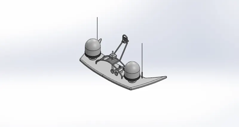
(a) Radar Mask
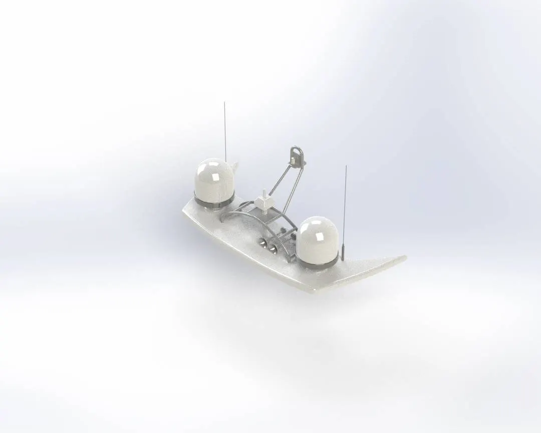
(b) Rendered Image of Radar Mask
Assembly of Predator Yacht
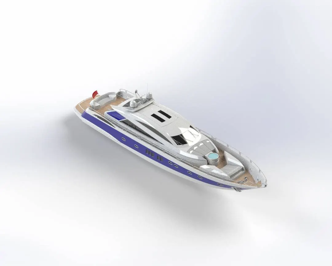
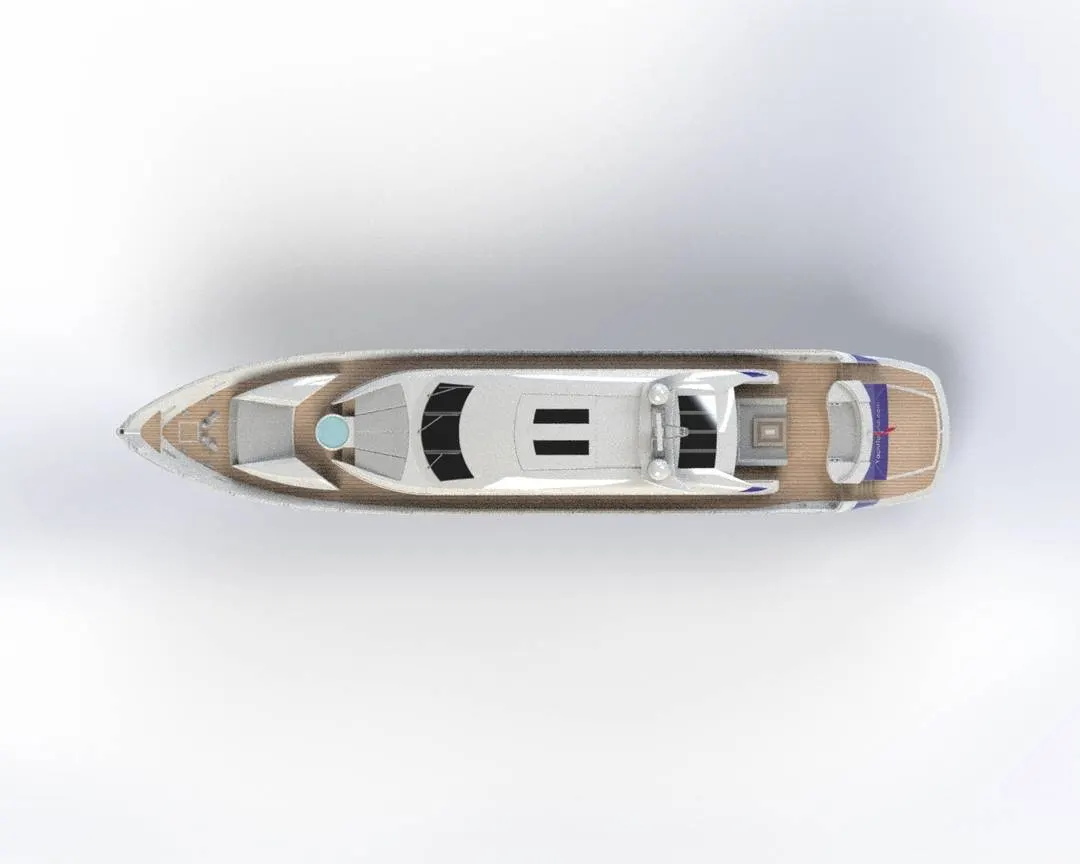
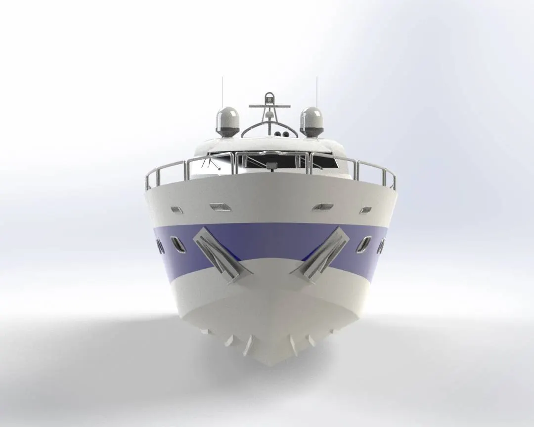
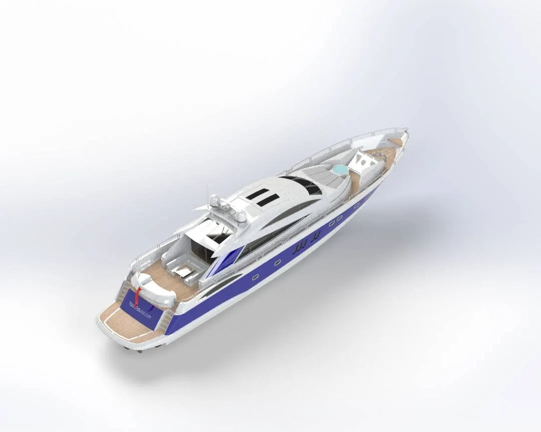
All the designed components are taken to the assembly section in the Solidworks and using different mate features like coincident, concentric, parallel etc., the entire assembly of the American Chopper is created.
The assembled motorcycle is now taken to the rendering.
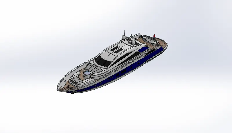
(a) Assmebly Of Predator Yacht
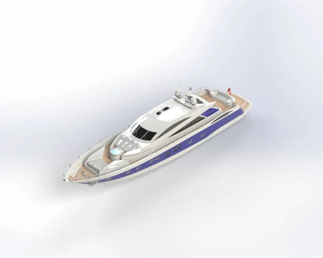
(b) Rendered Image Of the Assembly
Rendering of the Predator Yacht
- Rendering is the process of creating the photorealistic model of the Predator Yacht with the environment.
- Rendering has been done in the following ways in Solidworks:
- Photoview 360
- Solidworks Visualize
- The photorealistic model of the chopper is rendered into realistic image with different environments and views.
Conclusion:
- The parts of the Sunseeker Predator Yacht are sketched and modelled in the Solidworks.
- The parts are inserted into the assembly environment and by applying the mates feature Yacht is assembled.
- The realistic image was rendered with the use of the Photoview 360 & Solidworks Visualize.