Advanced Sheet Metal Design Using NX Cad Challenge_6_Bracket
MODELLING OF SHEET METAL BRACKET
OBJECTIVE
Modelling a Sheet Metal Bracket using NX CAD. Write a detailed report on Sheet Metal Component with good explanation on Sheet Metal modelling tools applied throughout the modelling. Also attach the Final model Images of Sheet Metal Bracket.
INTRODUCTION
Sheet metal is metal formed by an industrial process into thin, flat pieces. Sheet metal is one of the fundamental forms used in metalworking, and it can be cut and bent into a variety of shapes.
Siemens NX CAD software is a flexible and powerful integrated solution in sheet metal modelling that can helps us to deliver better products faster and more efficiently. NX delivers the next generation of design, simulation, and manufacturing.
DESIGN METHODOLOGY
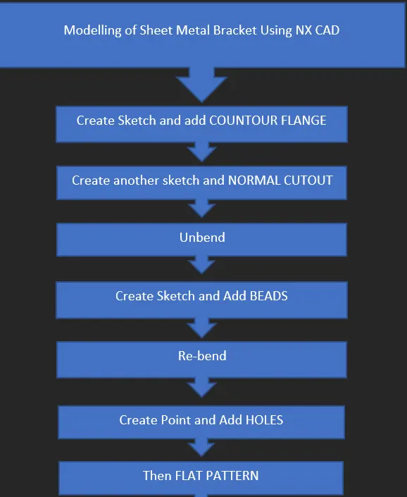
DESCRIPTION
Open NX CAD
Create a new File in sheet metal model
Create a sketch as shown below
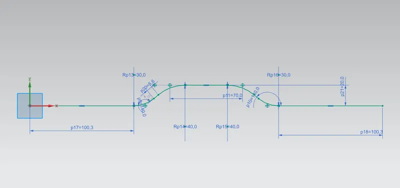
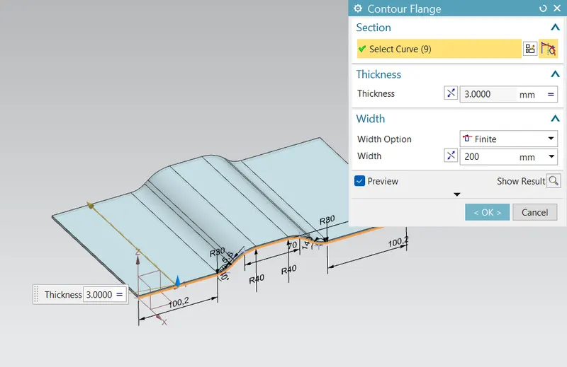
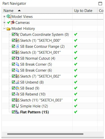
Then create a Countour flange with thickness 3mm
It used to create base feture or secondary feature of a sheet metal part by extruding a sketch created along a particular vector
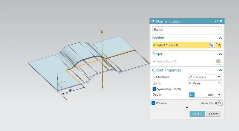
Then Create a Sketch and Normal Cutout
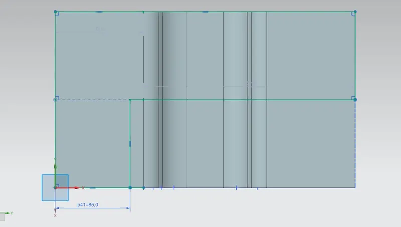
Break corner and Unbend
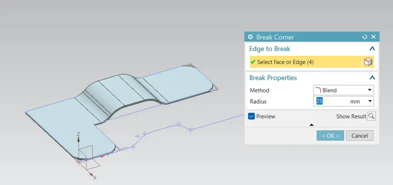
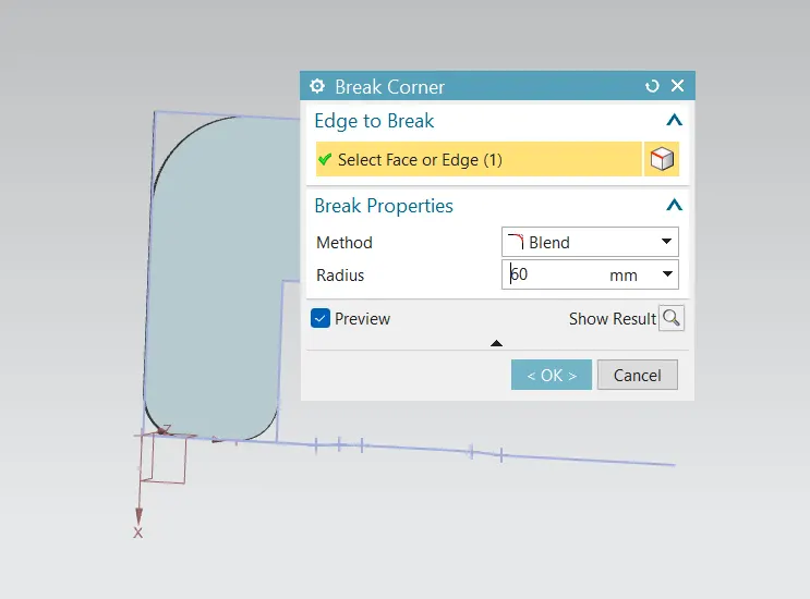
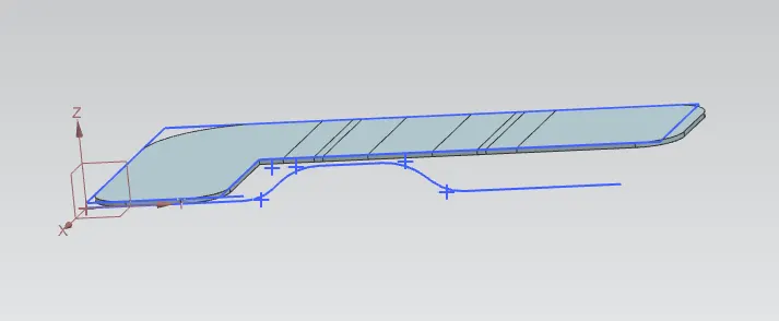
Create a sketch and Create a beads
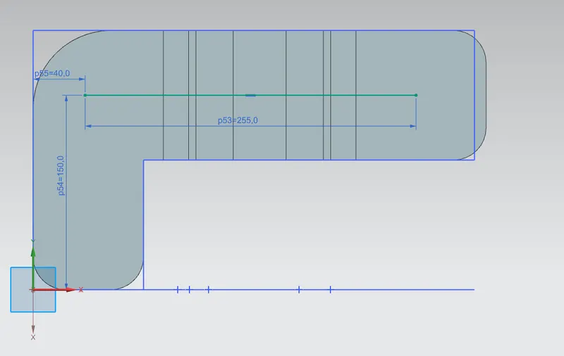
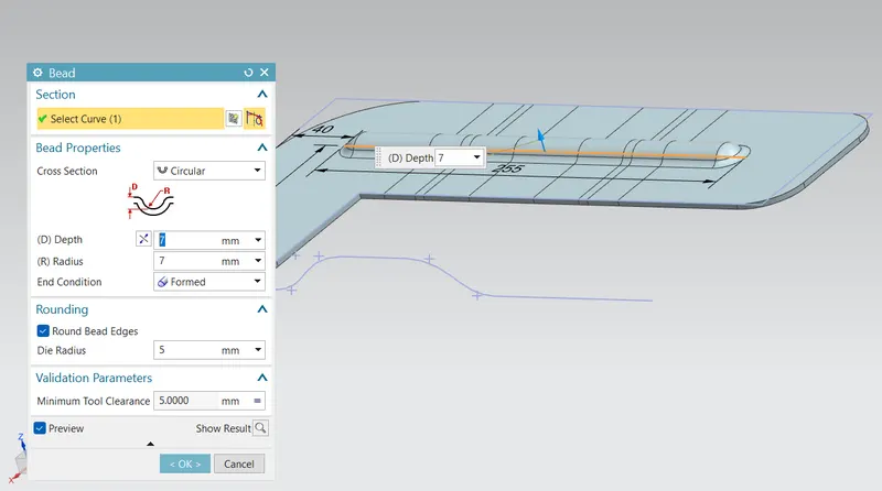
Rebend
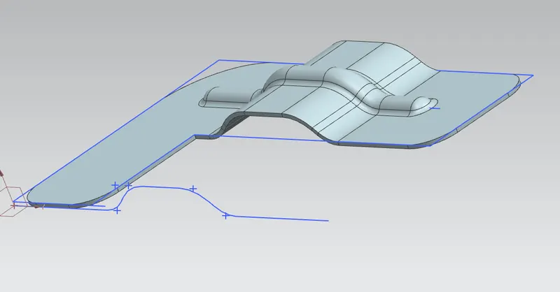
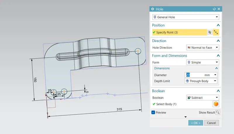
Create the point and then add holes
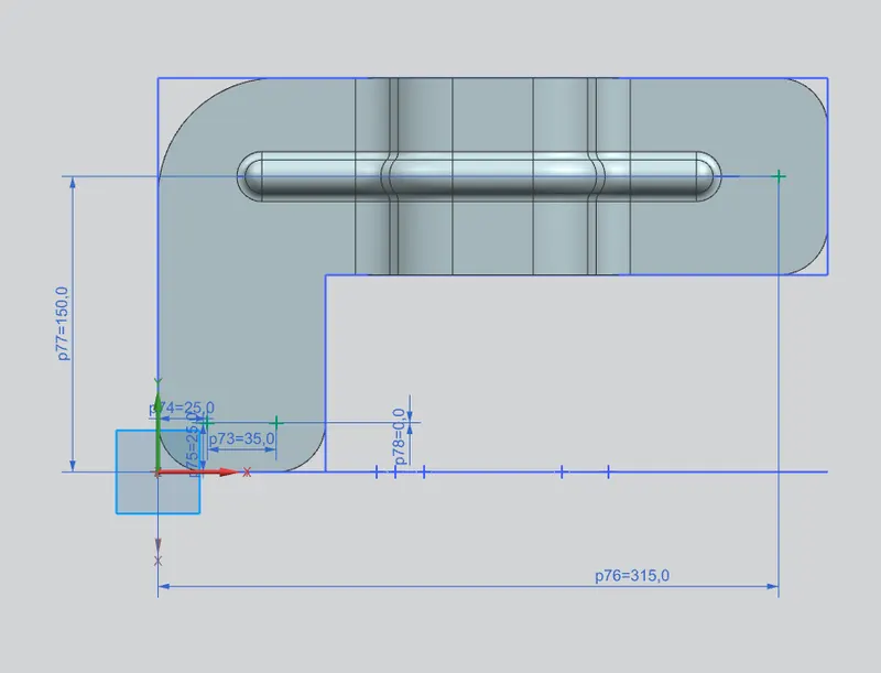
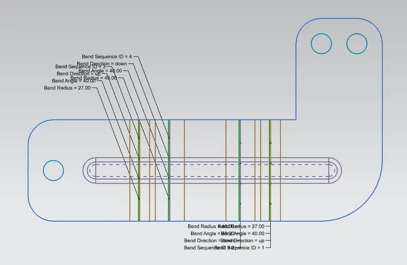
Flat pattern
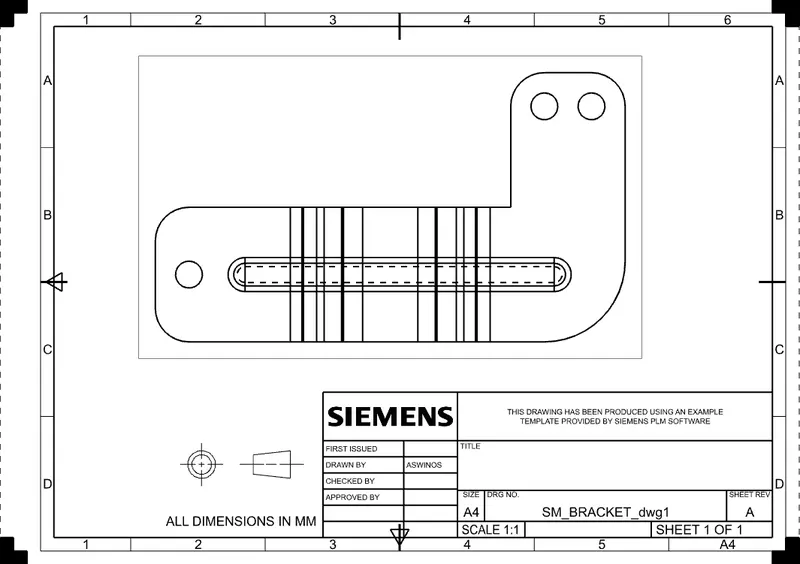
DRAFTING
Screenshots
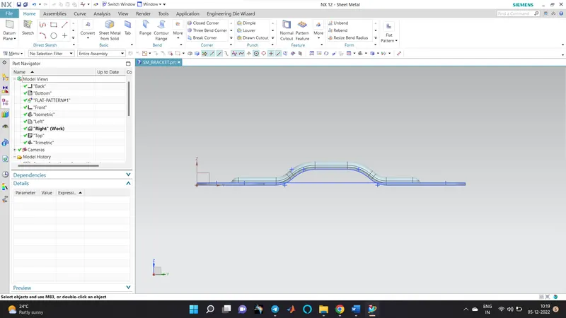
FRONT VIEW
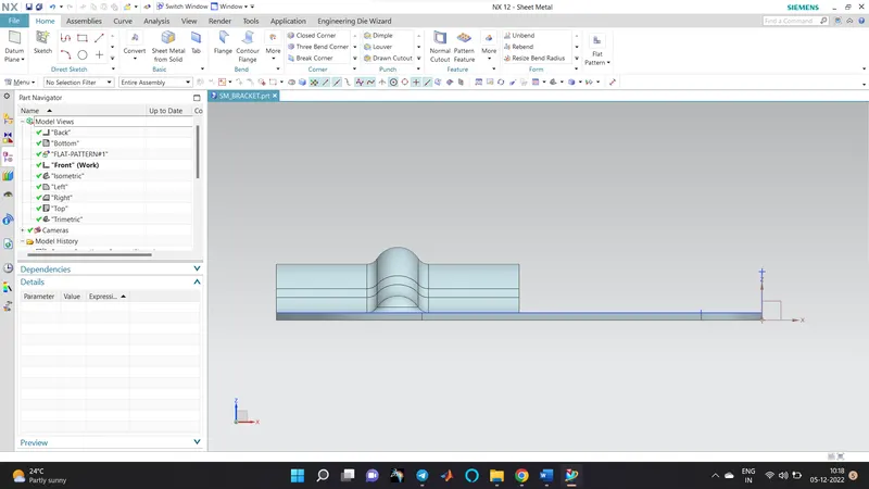
SIDE VIEW
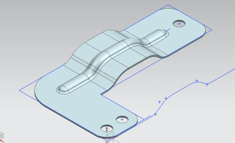
ISOMETRIC VIEW
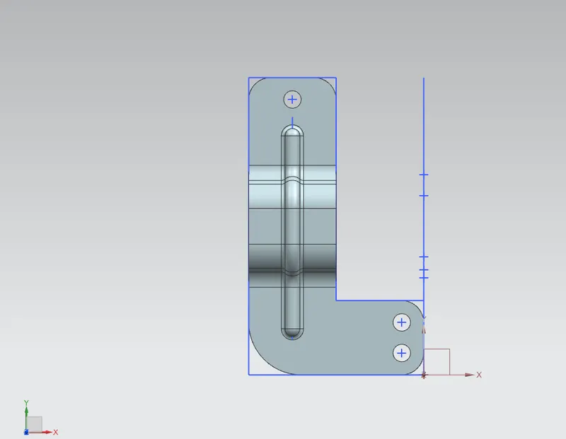
TOP VIEW
FEATURE TREE
Conclusion
Hence we have created the Bracket Using NX CAD