Advanced Sheet Metal Design Using NX Cad Challenge_6_Bracket
TITLE:- Metal Bracket Using Advanced Sheet Metal options in NX Cad
OBJECTIVE:-
Bracket fabrication using NX cad command
INTRODUCTION :-
These basic guidelines for sheet metal fabrication include important design considerations to help improve part manufacturability, enhance cosmetic appearance, and reduce overall production time.
Sheet Metal Fabrication is the process of forming parts from a metal sheet by punching, cutting, stamping, and bending. 3D CAD files are converted into machine code, which controls a machine to precisely cut and form the sheets into the final part.
Sheet metal parts are known for their durability, which makes them great for end use applications (e.g. chassis). Parts used for low volume prototypes, and high volume production runs are most cost-effective due to large initial setup and material costs.
Because parts are formed from a single sheet of metal, designs must maintain a uniform thickness. Be sure to follow the design requirements and tolerances to ensure parts fall closer to design intent and cutting sheets of metal.
DESIGN METHODOLOGY
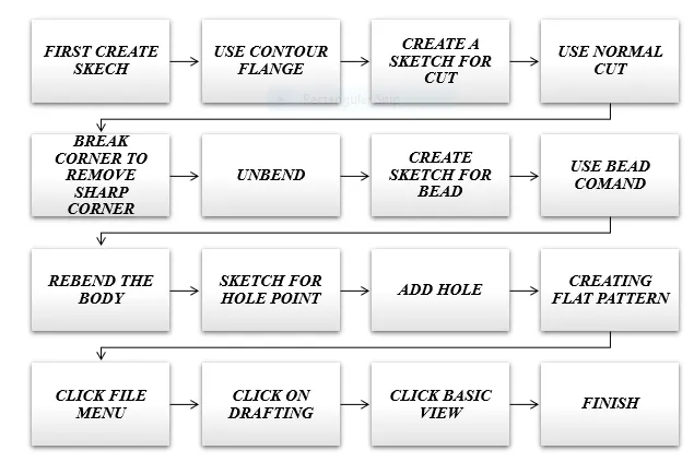
DESCRIPTION (Need to explain tools/ Features used while designing)
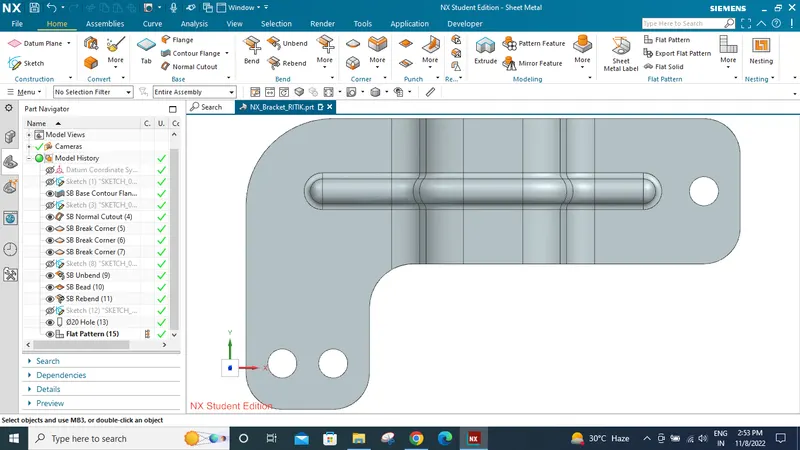
- Use the Contour Flange to Creates a base feature by extruding a sketch along a vector, or adds material by sweeping a sketch along an edge or a chain of edges.
- Use the Normal Cutout command to cut material by projecting a sketch onto the model and then cutting perpendicular to the faces intersected by the projection.
- Use the Break Corner command to round or chamfer sharp corners of a tab or flange.
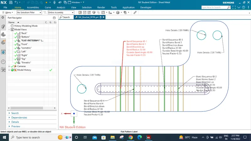
- Use the Unbend command to unbend a portion of the part to construct cutout features, hole features, or deform features across a bend. You can later reform the bend to represent the true formed state of the model.
- Use the Bead command to lift material along the contour of a sketch that simulates a stamping tool. Beads can also be created to stiffen sheet metal parts.
- Use the Rebend command to return an unbend feature to its previous bent state. Any features added after the unbend operation are properly repositioned during the rebend operation.
- Use the hole to one or more solid bodies in a part or assembly with options for counterbored, countersunk, and threaded.
screenshots of Model . (Front View, Side View, Isometric View and the Top View)
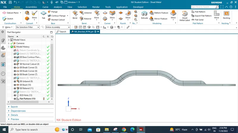
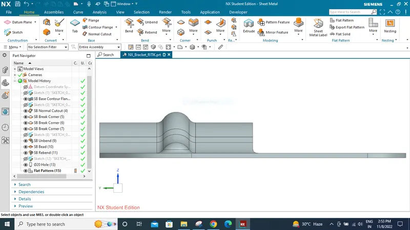
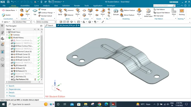
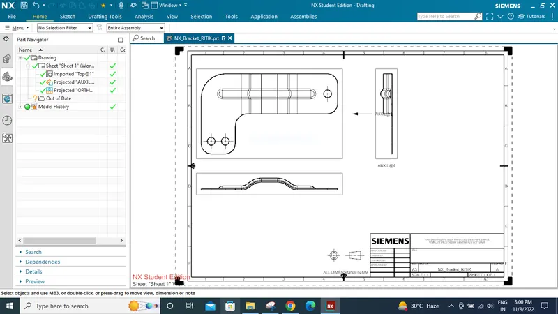
Detailed Drawing
CONCLUSION
HENCE COMPLEATED THE DESIGNING OF BRACKET USING NX CAD ADVANCE FEATURE.
THANK YOU