Advanced Sheet Metal Design Using NX Cad Challenge_6_Bracket
Bracket
Objective: Design a sheet metal bracket in sheet metal using Siemens-NX.
Introduction
Siemens-NX is a CAD/CAM/CAE software used in many aerospace, machinery, automobile industries, and many other industries. Using Siemens-NX the sheet metal and surface design can be handled easily. The brackets can be made by bending, stamping, and punching. While designing these processes need to be considered. The design should be theoretically possible to make from the blank material.
Design Methodology
Description
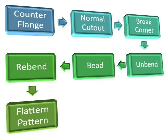
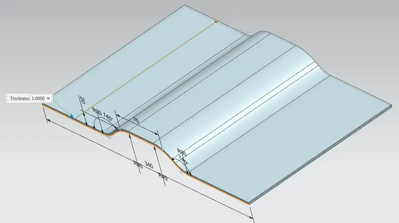
The designing process is started by creating a sheet metal extrude with a support of a sketch. The ‘Counter Flange’ command is used for the base model.
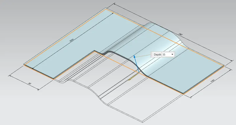
The model is then cut down using the ‘Normal Cutout’ command. A sketch is made as reference thus cutouts.
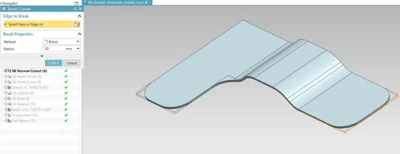
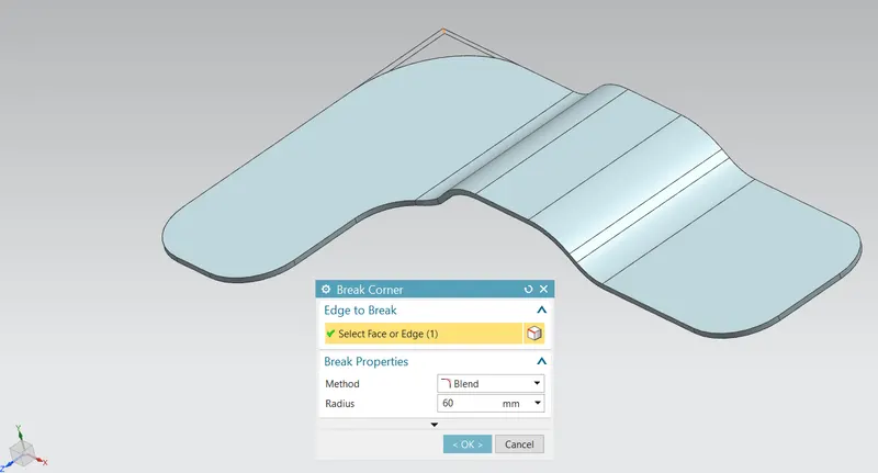
The sharp corners are smoothened by introducing fillets at the corners. The command ‘Break Corner’ is used.
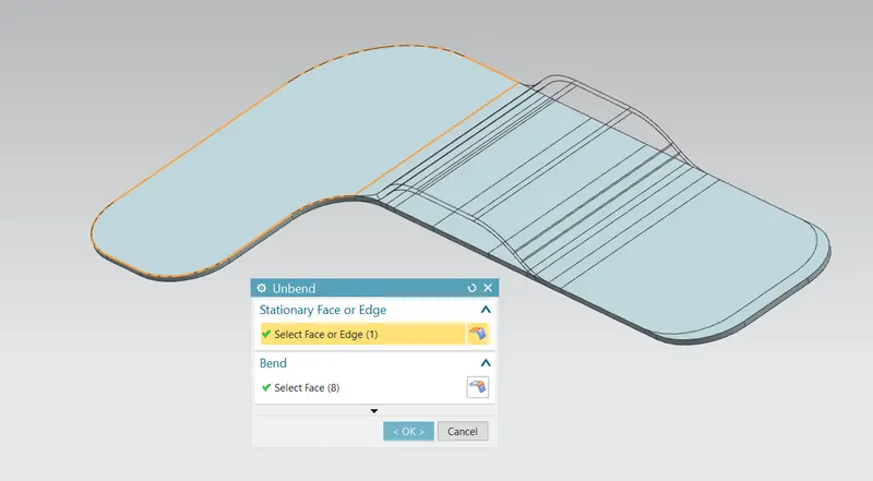
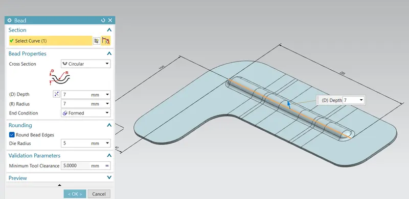
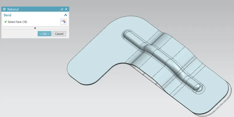
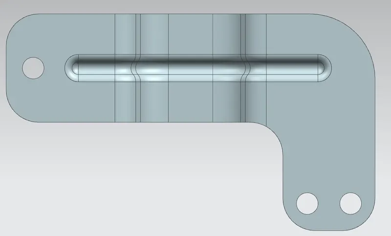
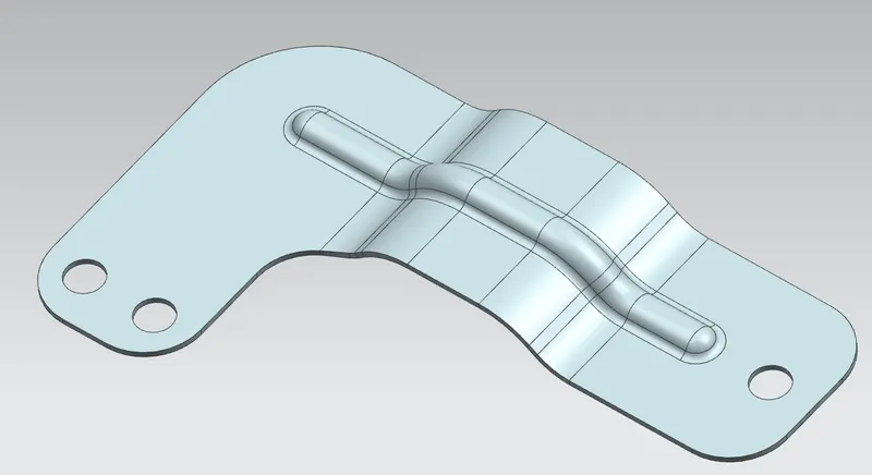
To strengthen the design the model is introduced with a projected bend-like structure. This is made possible by using the command ‘Bead’ and a sketch as its support.
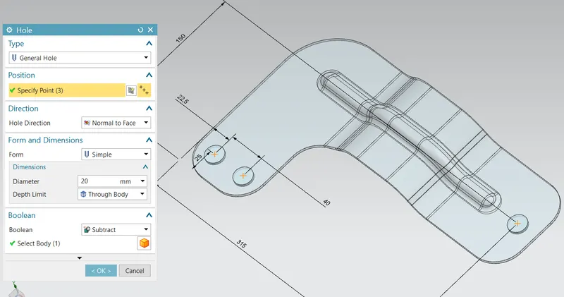
The holes are introduced on the models by using the command 'Hole'.
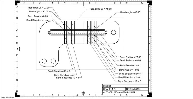
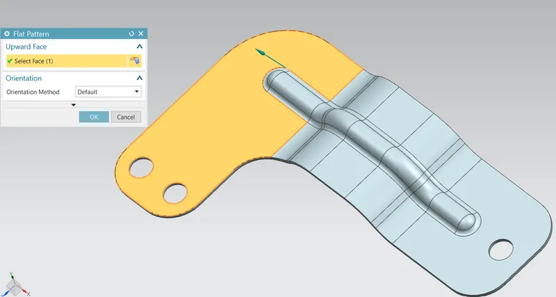
The ‘Flat Pattern’ is used to make a blank model, which can be introduced during drafting.
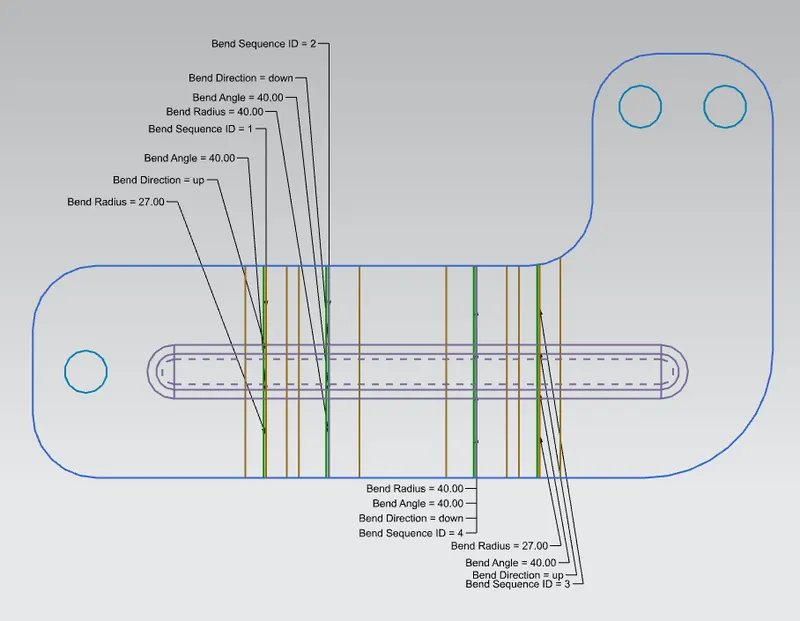
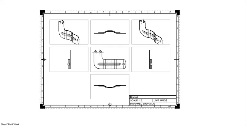
Standard View
Front View
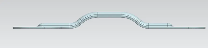
Side view
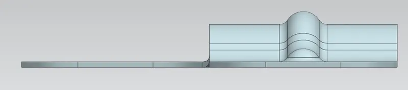
Top View
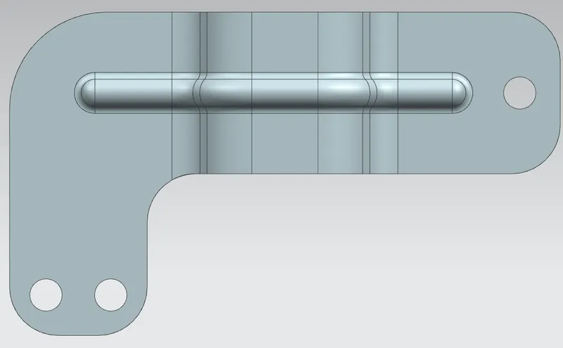
Bottom View
Isometric View
Drawings
Draft Model