Advanced Sheet Metal Design Using NX Cad Challenge_6_Bracket
Title:- Design Backet in Using Sheet Application Using NX CAD.
Objective:-
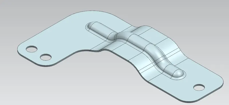
In this Project I have Created Bracket L-shape with the help of 2D sketches.
Introduction:-
- In mechanical engineering a bracket is any intermediate component for fixing one part to another, usually larger, part. What makes a bracket a bracket is that it is intermediate between the two and fixes the one to the other.
- A simple rigid structure in the shape of an L, one arm of which is fixed to a vertical surface, the other projecting horizontally to support a shelf or other weight.
Uses:-
- Brackets can support many architectural items, including a wall, balcony, parapets, eaves, the spring of an arch, beams, pergola roof, window box, or a shelf.
Design Methodology:-
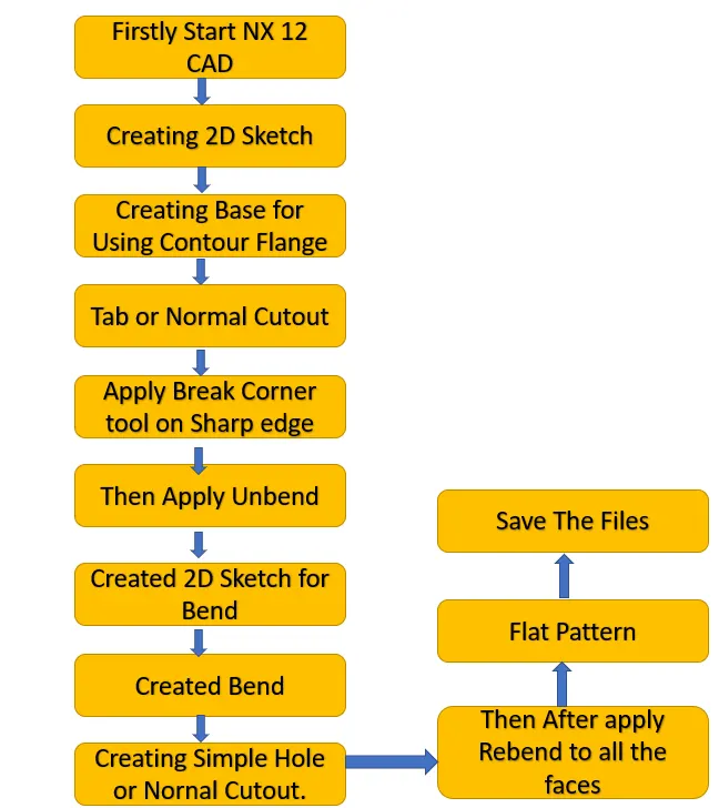
Description of tools/ Features used for designing as shown as following:-
Creating 2D Sketch:- Creating 2D sketch for Base thickness part.
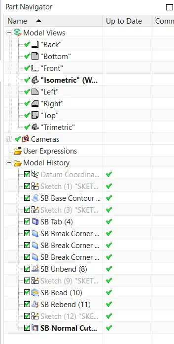
Contour Flange:- In Siemens nx sheet metal contour flange command use to create a base feature by extruding a sketch along a vector, or adds material by sweeping a sketch along an edge or chain of edge.
Tab Feature:- Creates a base of the sheet metal by using a sketch.
Bend:- This command is used for creating bend on sheet metal.
Normal Cut Out:- Use the Normal Cutout command to cut material by projecting a sketch onto the model and then cutting perpendicular to the faces intersected by the projection.You can use planar sketches or 3D curves to specify the section for the normal cutout.
Break Corner:- Break corner is used to provide a fillet type faster to sharpe corners of the sheet metal it is used to provide safety as well as to relievestress concentraction.
Hole:- In Siemens NX has a command that users could create or drill standard sized holes with it. This command is called Hole and you can activate this command by clicking on it. You can create various kinds of holes that generally used in mechanical structures according to accepted standards.
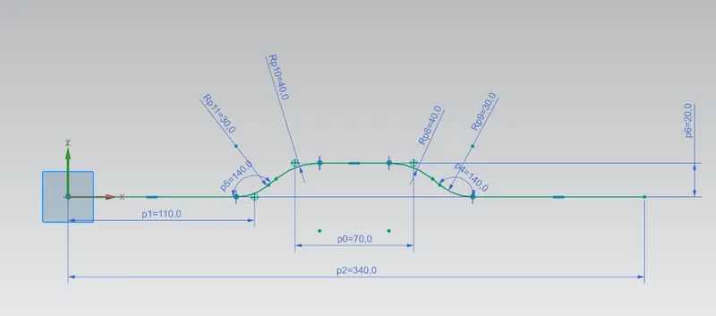
Created 2D Sketch for Bracket:-
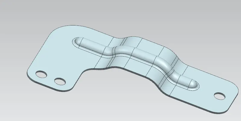
Final Part:-
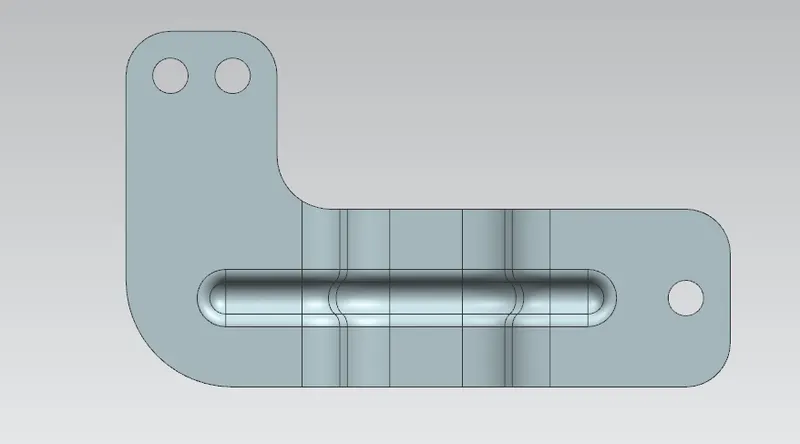
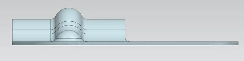
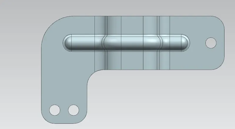
Model Views as shown as following:-
Front View:-
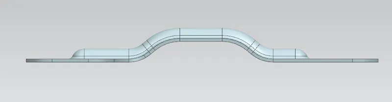
Bottom View:-
Side View:-
Top View:-
Isometric Veiw:-
Tree Feature:-
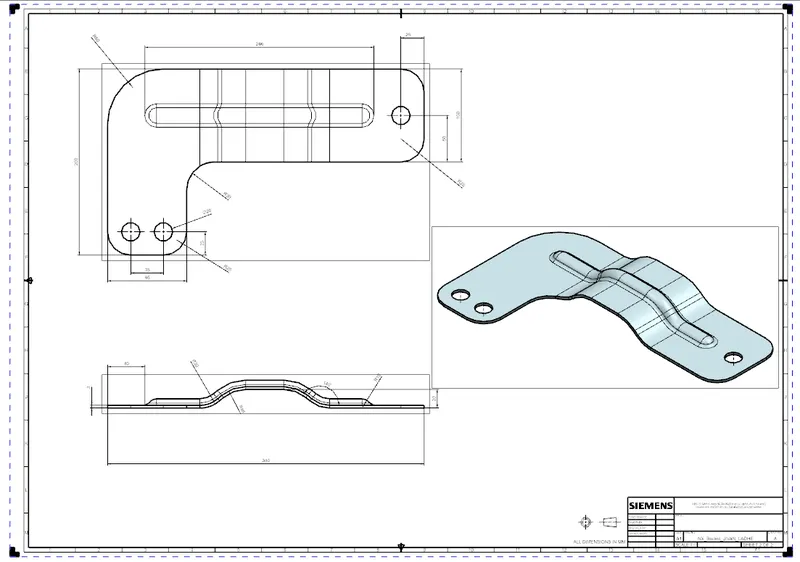
Drawing Sheet:-
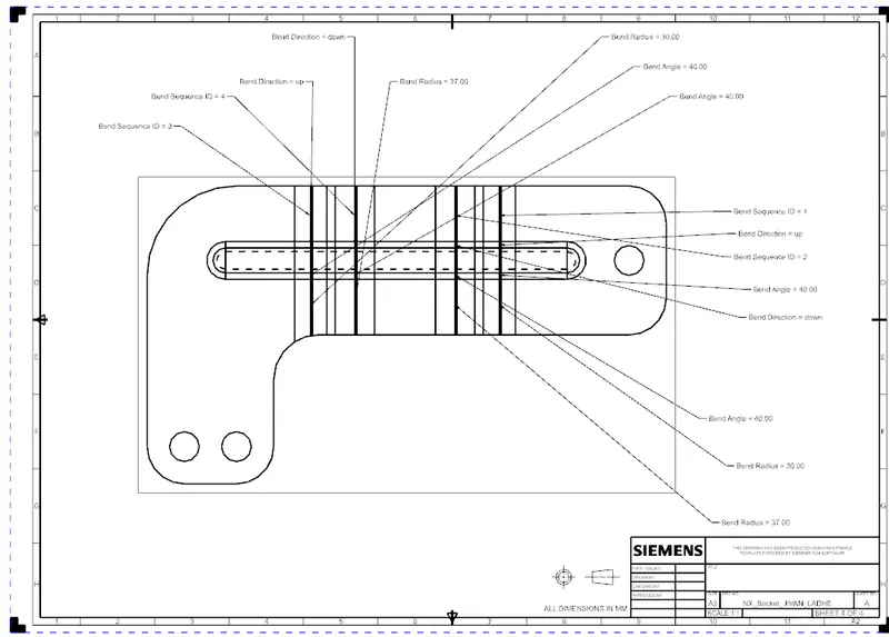
Detailed Drawing Sheet:-
Conclusion:-
In this project I have Design the Backet Using in sheet metal application using NX CAD and Study about Drafting Tool in NX. CAD