Advanced Sheet Metal Design Using NX Cad Challenge_2_Box Assembly
Title of the Project
NX_BOX_ASSEMBLY
Objective
To model box assembly according to provided dimensions
Introduction
Sheet metal components are mainly used as casing or closures. One such application is box.
Design methodology / approach (To be explained with the help of Flowcharts only)
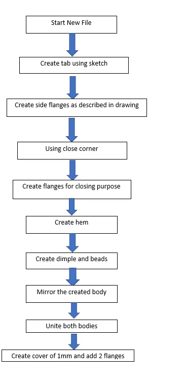
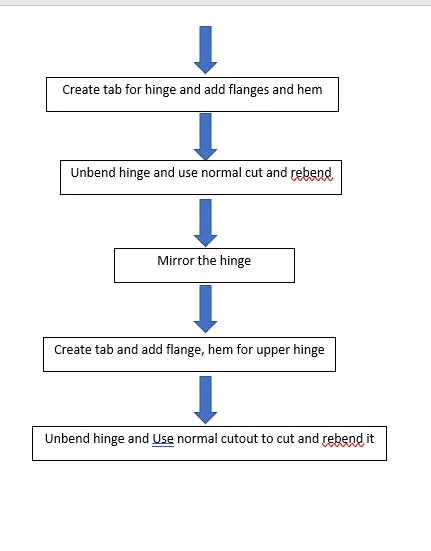
Description (Need to explain tools/ Features used while designing)
Sketch a tab of 150x200x1mm
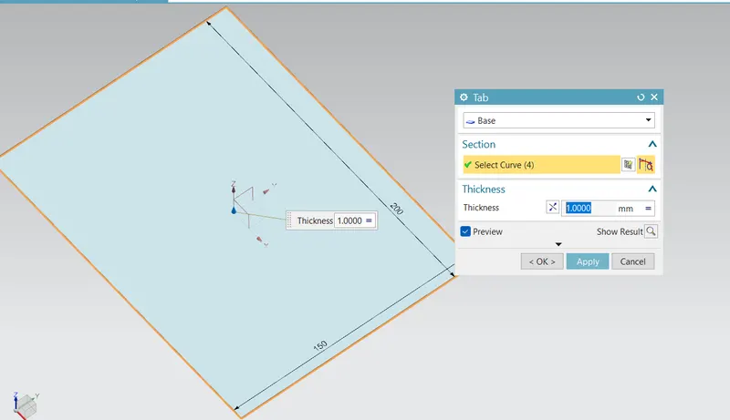
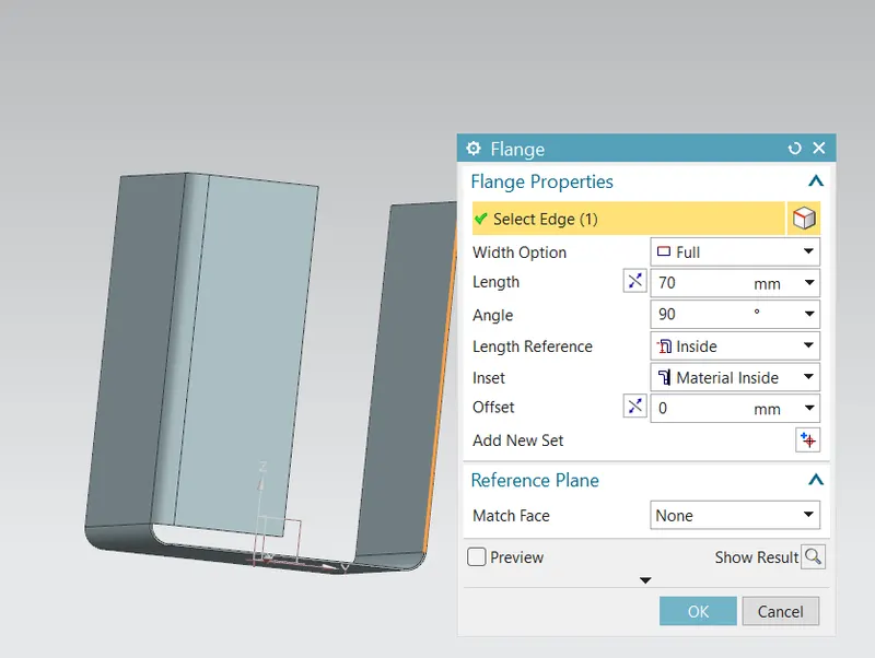
Developed flange(normal to XY)
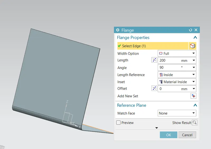
Developed flange(normal to XZ)
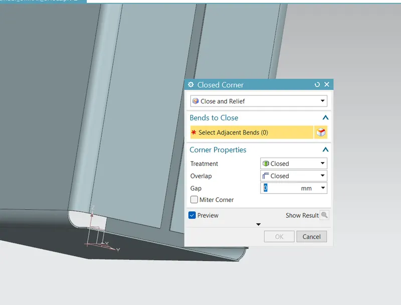
Close the corner
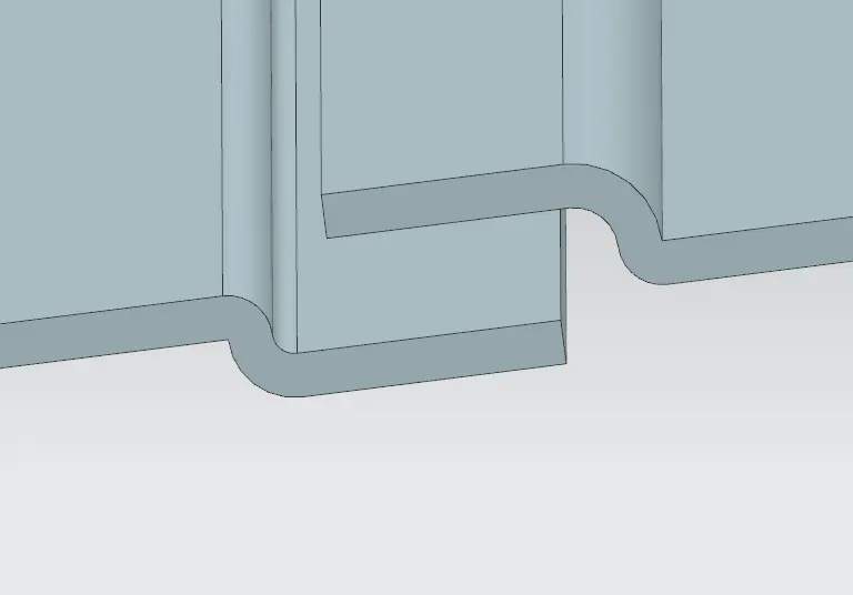
Create flanges for closing purpose
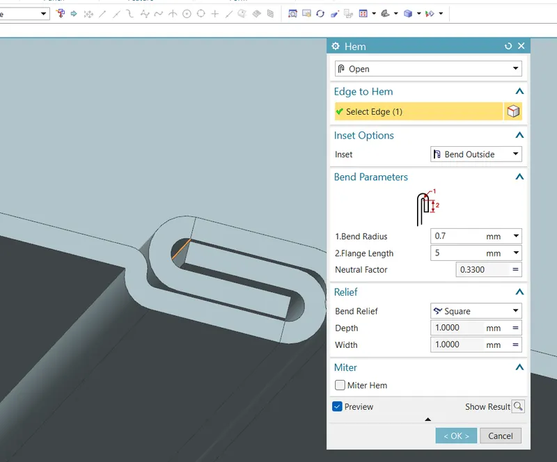
Create hem
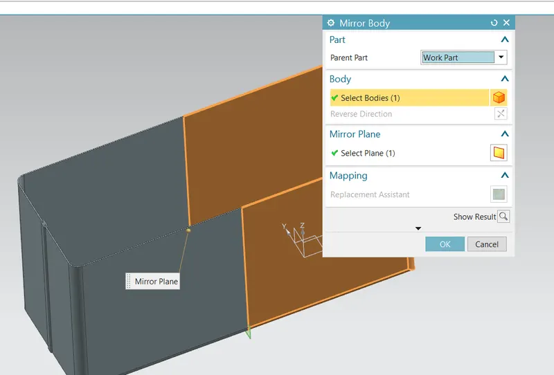
Mirror the body
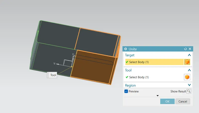
Unite two bodies
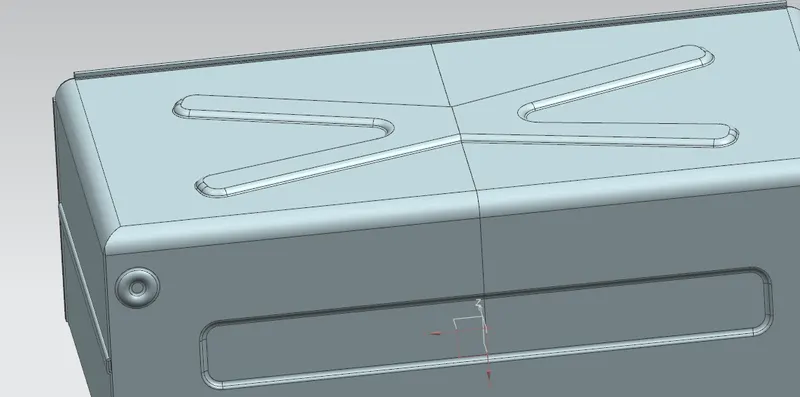
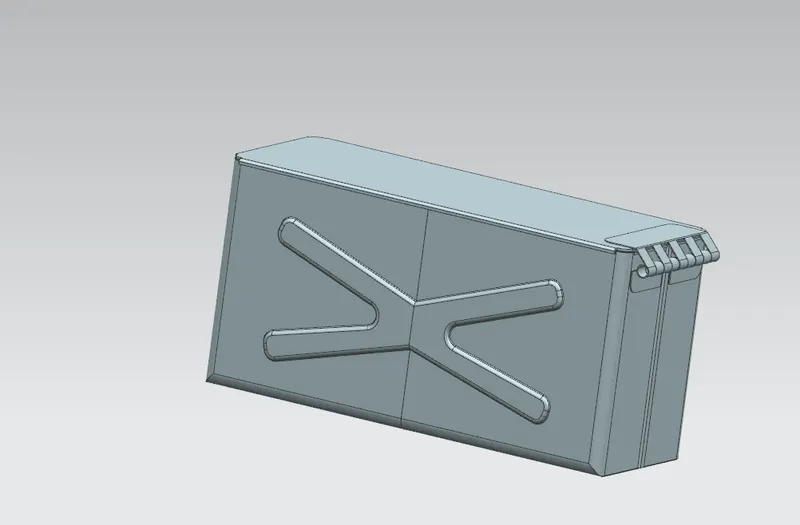
Create X-shaped dimple on longer face while rectangular dimple on bottom side of the box
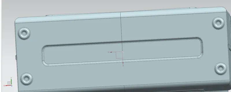
Create beads at four corners of box on bottom side
Create sketch for cover
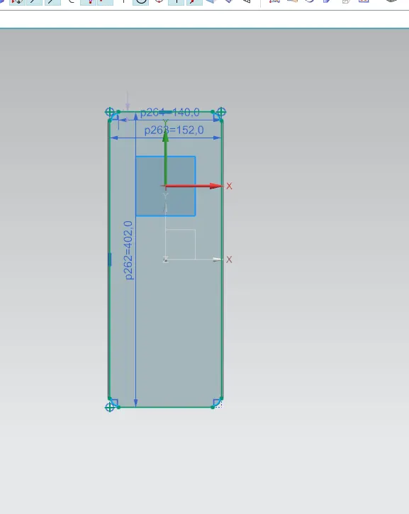
Create base tab for cover of 2mm
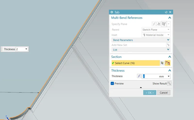
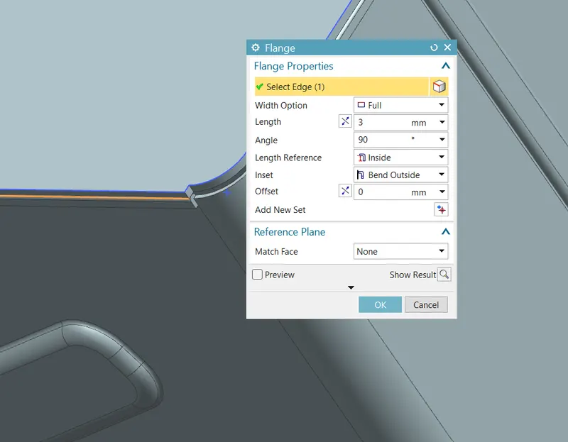
Create flanges for cover on both longer sides
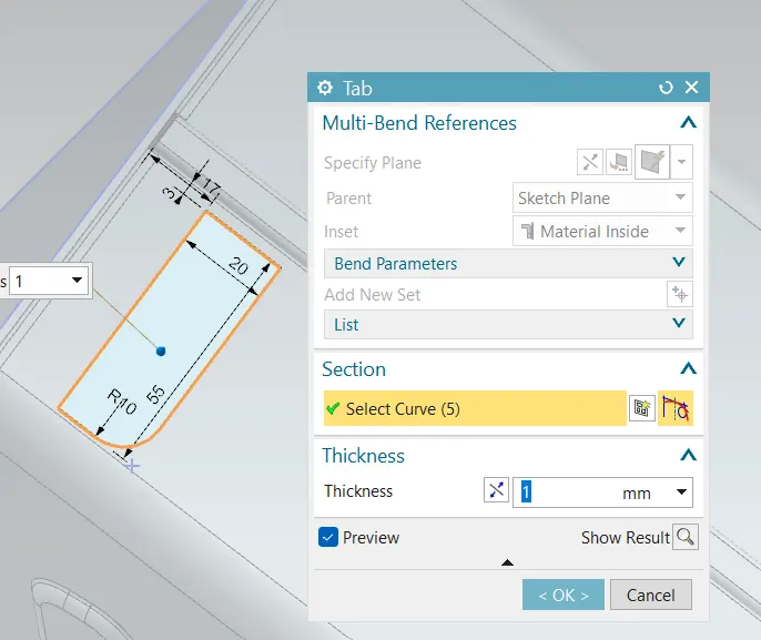
Create sketch for tab of hinge base
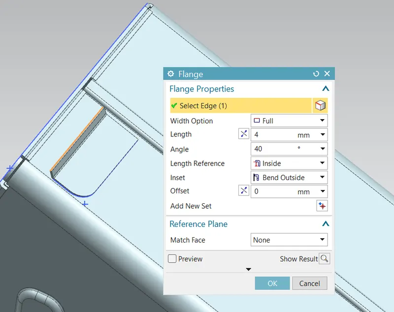
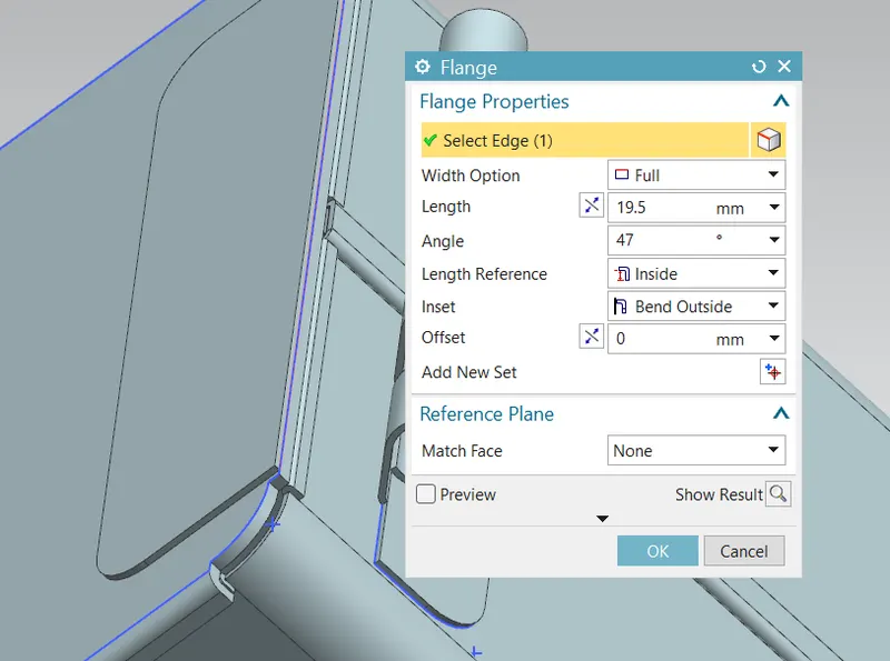
Create flanges over tab as described in drawing
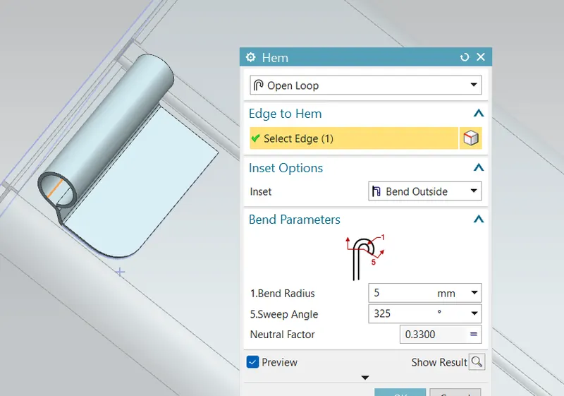
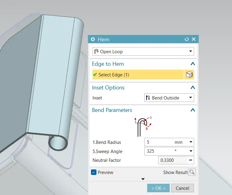
Create hem as open loop
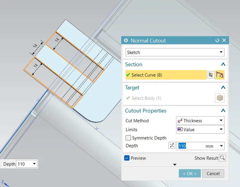
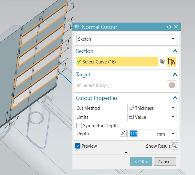
Unbend the hing. Use normal cut to cut hinge for engagement purpose. Rebend the hinge
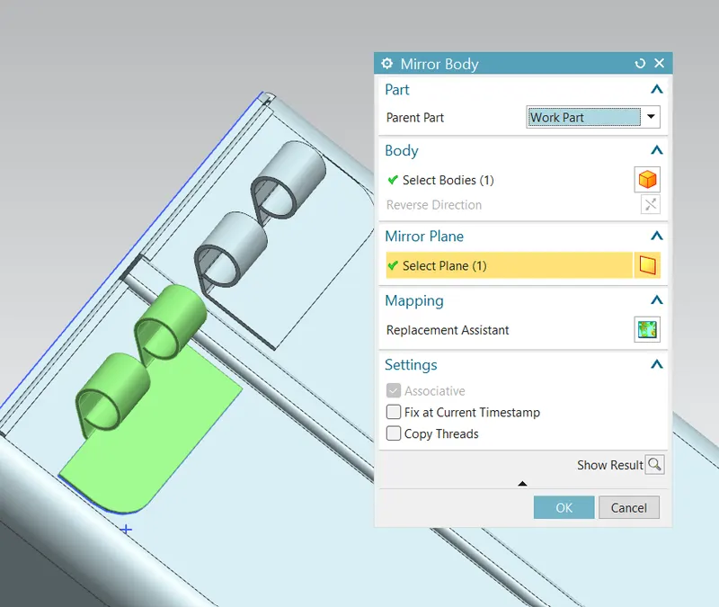
Mirror hinge for other side
Create tab using sketch for upper hinge and create flange. We need to adjust length and angle in order to engagement with lower hinge
Create open loop hem
Unbend the upper hinge. Use normal cut to make slot for engagement and again rebend
Upload a min of four screenshots of Model in the report. (Front View, Side View, Isometric View and the Top View)
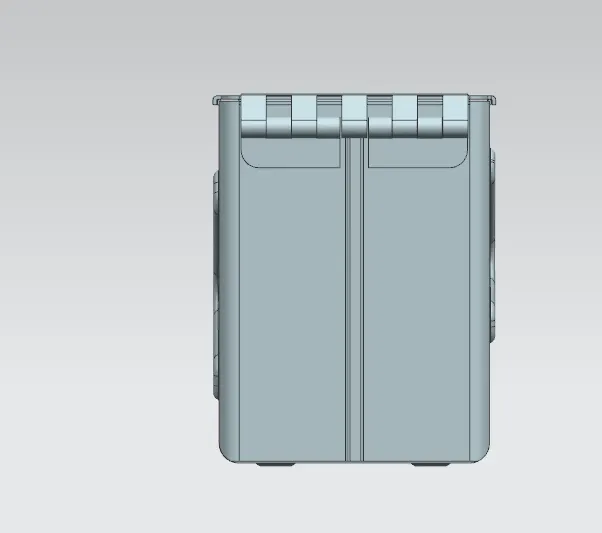
Front View
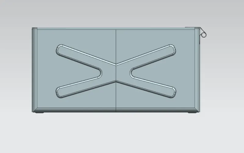
Top view
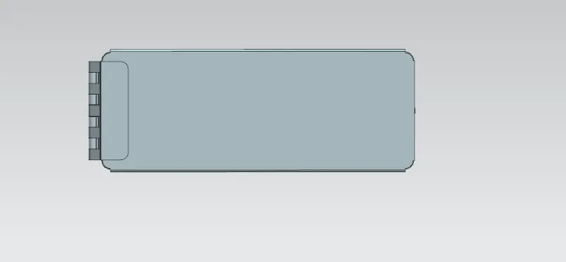
Side view
Iso view
Conclusion
In this way box along with cover and hinges is modeled according to drawing in NX.