Advanced Sheet Metal Design Using NX Cad Challenge_2_Box Assembly
MODELLING OF SHEET METAL BOX
OBJECTIVE
In this challenge we are going to modelling a sheet metal BOX using Siemens NX CAD and also a detailed explain about the sheet metal tools used for the operation.
DESIGN METHODOLOGY
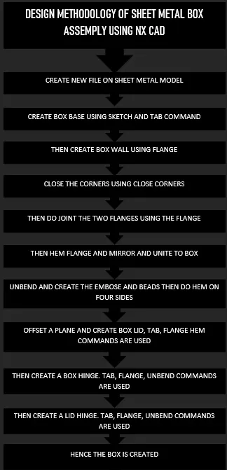
DESCRIPTION
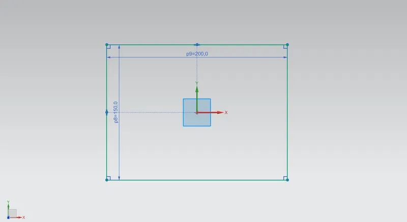
CREATE SKETCH FOR BASE
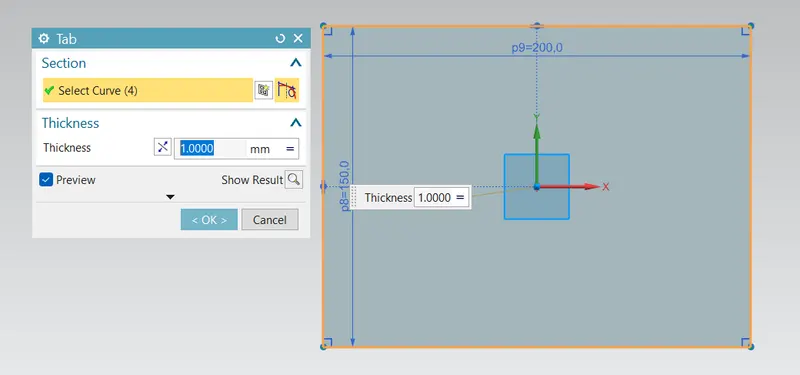
THEN TAB WITH 1MM THICKNESS
USE FLANGE TO CREATE THE WALL
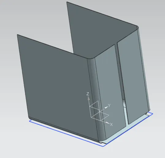
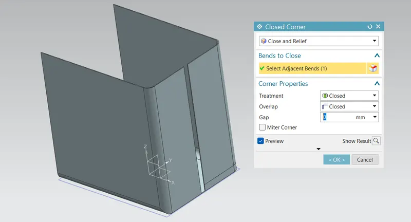
THEN USE THE CLOSED CORNERS TO CLOSE THE SIDE OF THE WALL
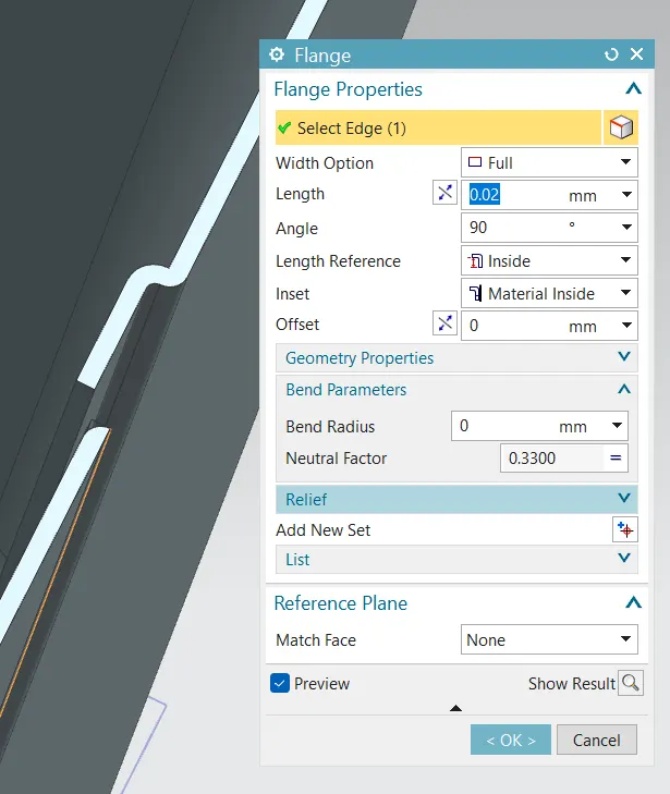
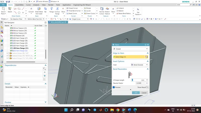
FLANGE AND HEM FOR CREATE JOIN IN THE REAL SHEET METAL
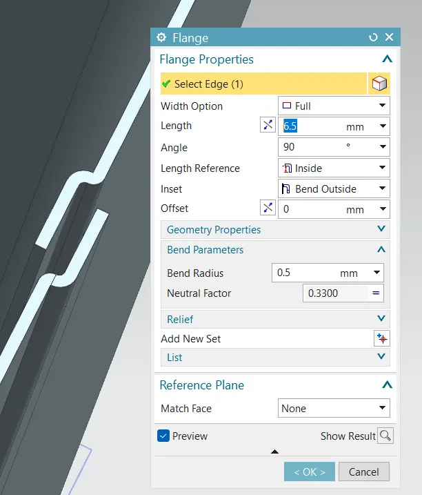
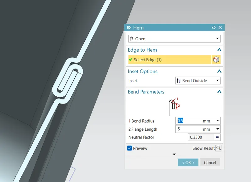
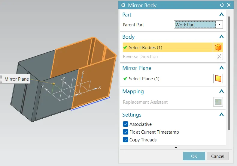
THEN MIRROR THE WHOLE BODY
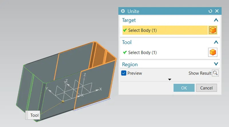
THEN JOIN THE TWO BODY BY USING THE UNITE COMMAND
THEN UNBEND
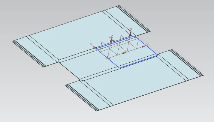
SKETCH FOR THE EMBOSSE AND DIMPEL IT AND MIRROR IT.
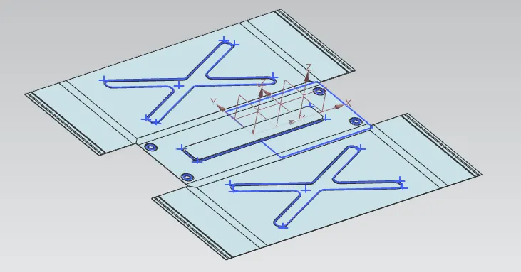
REBEND AND GIVE THE HEM
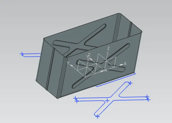
THEN START TO CREATE THE LID
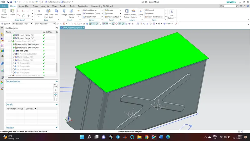
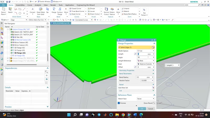
THEN CREATE THE BODY HING
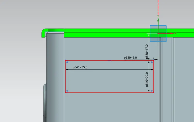
TAB AND FLANGE TO THIS SHAPE
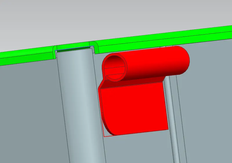
THEN UNBEND AND MAKE THE NORMAL CUTOUT
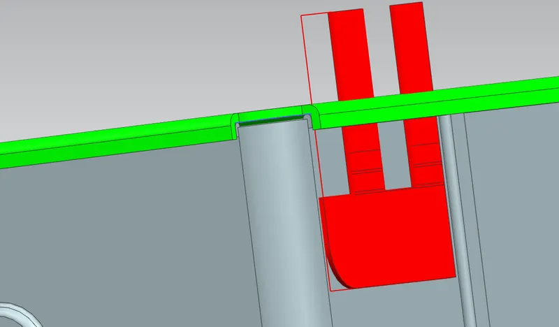
REBEND
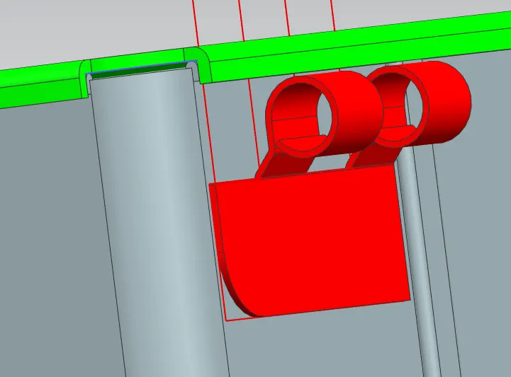
MIRROR BODY
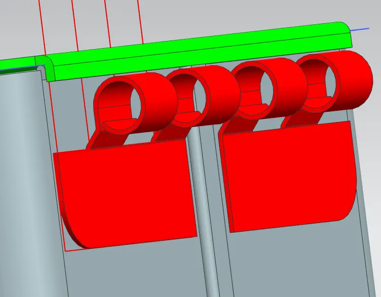
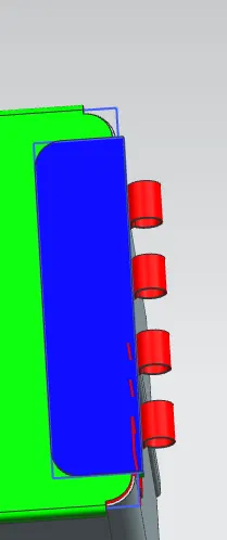
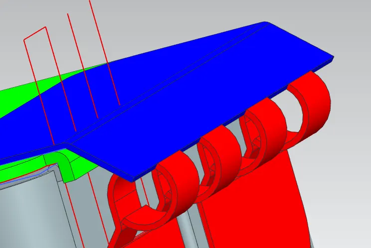
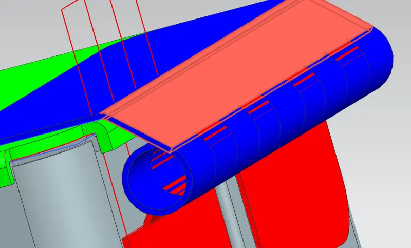
THEN CREATE HINGE OF THE LID
USE SKETCH, TAB, CORNER BREAK AND FLANGE COMMAND FOR THAT
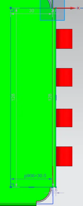
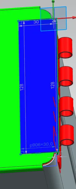
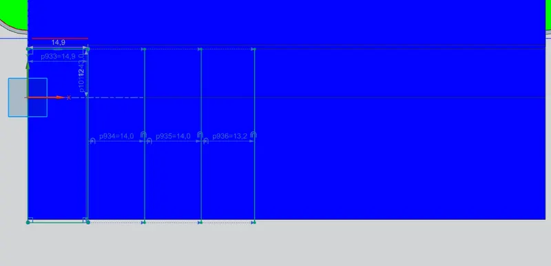
NORMAL CUTOUT
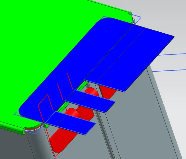
MIRROR FEATURE
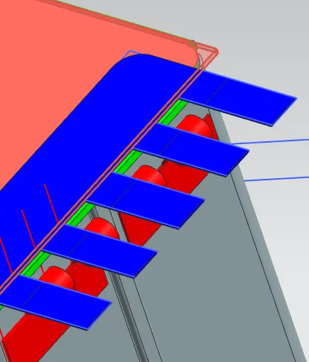
REBEND
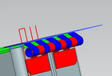
FLAT PATTERN AND DRAFT
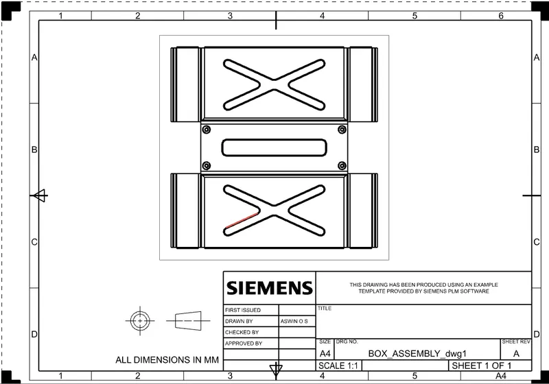
MODEL SCREENSHOT
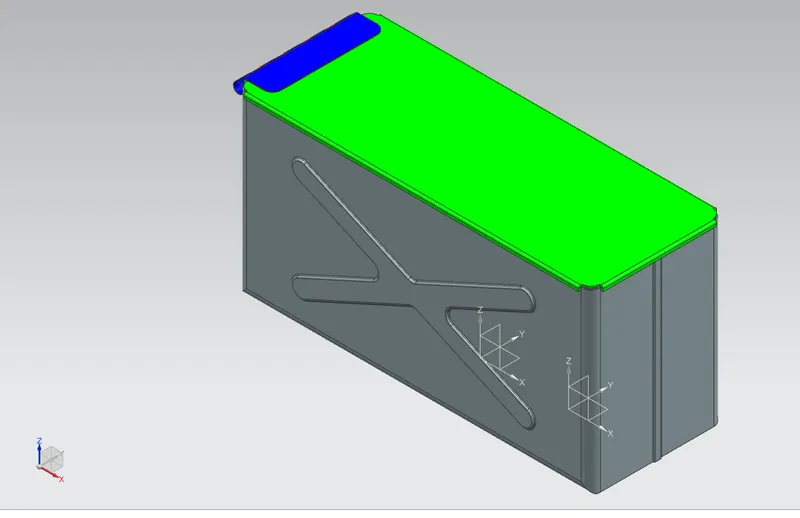
ISOMETRIC
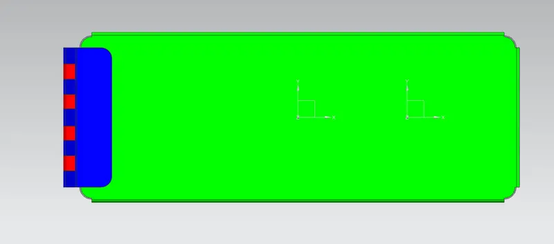
TOP
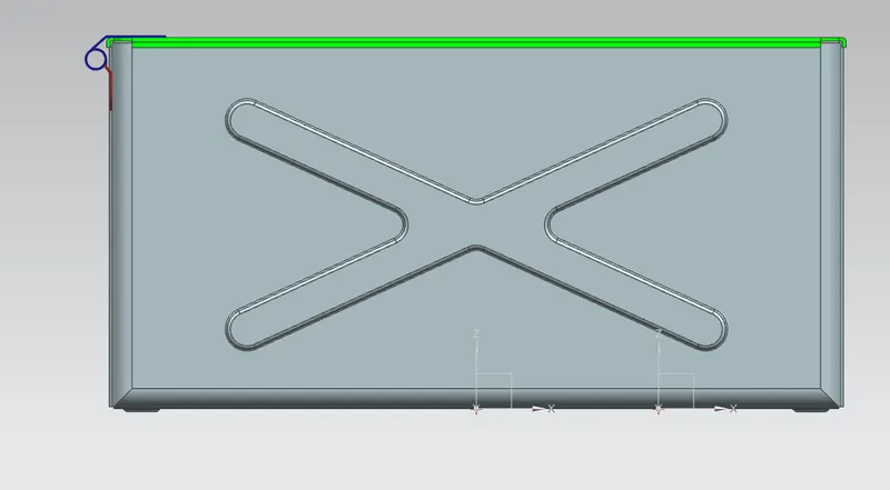
FRONT
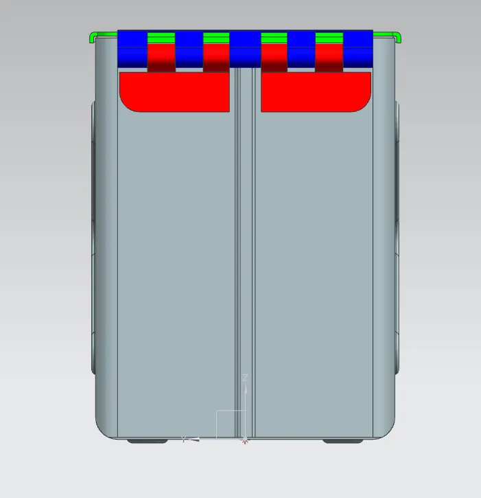
SIDE
CONCLUSION
By performing this challenge, I have learned how to use features like tab, flange, break corner, closed corner, dimple, hem flange, bead, rebend, datum plane, datum coordinate system (Datum CSYS), flat pattern, mirror feature, mirror body, unite, normal cutout and unbend by creating a box assembly.