Advanced Sheet Metal Design Using NX Cad Challenge_2_Box Assembly
BOX ASSEMBLY
Objective: Design a 3D box assembly using Siemen-NX sheet metal.
Introduction:
Sheet metal designing is a metal designing process carried out in many industries like the aerospace and automobile industry. The sheet metal works contain punching, cutting, bending, and stamping. In the case of box designing apart from the normal process hemming process also take place. All these processes need to be considered while designing each part and then assembling them.
Design Methodology
Description
Part – 1: Box Modeling
The body part is modeled first.
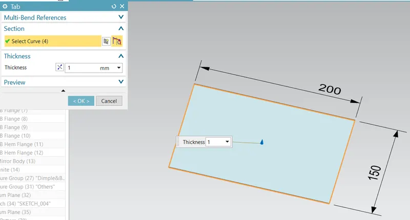
The body design is started with the ‘Tab’ command with help of a reference sketch.
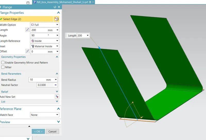
The flange is introduced on the tab feature to make side walls.
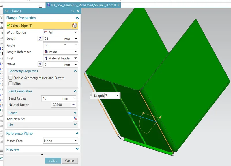
More flange is added to the design to make it like a box.
The open corner potion is closed using the ‘Close Corner’ command.
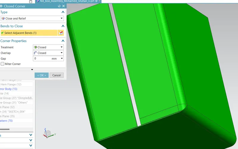
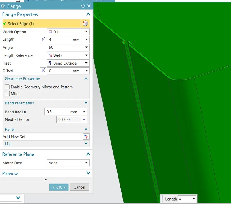
More flange is introduced to create hem flanges.
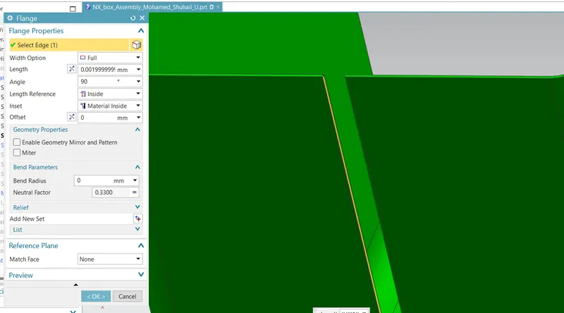
The flange to create the hem is made.
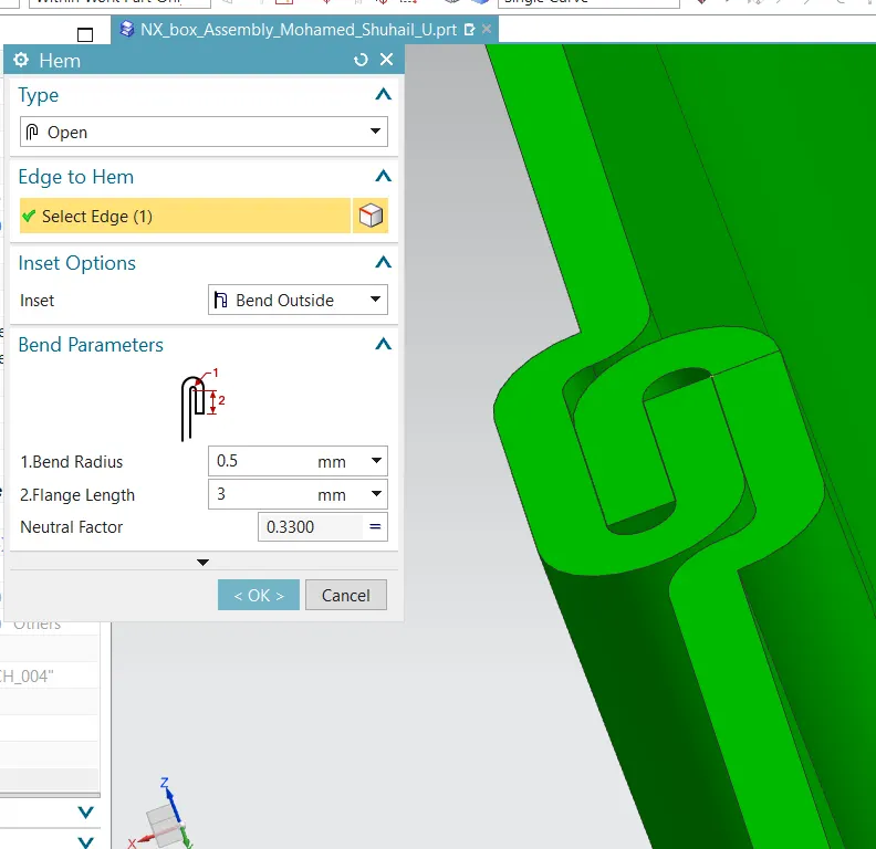
The open type hem is created using the ‘Hem command’. The hem wraps around itself and holds the structure. Thus, the structure looks like a closed model.
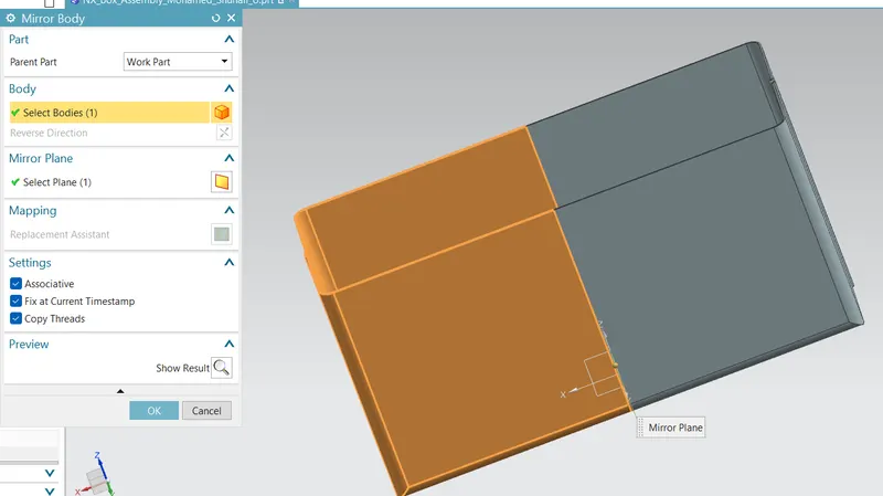
The entire body is mirrored using the ‘Mirror Body’ command. Once it is mirrored the main process to create a body of a box is completed.
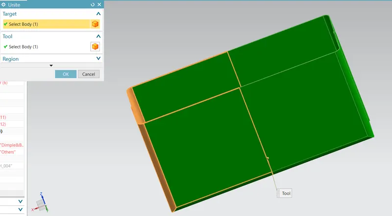
The mirrored bodies joint together so that they act as a single unit.
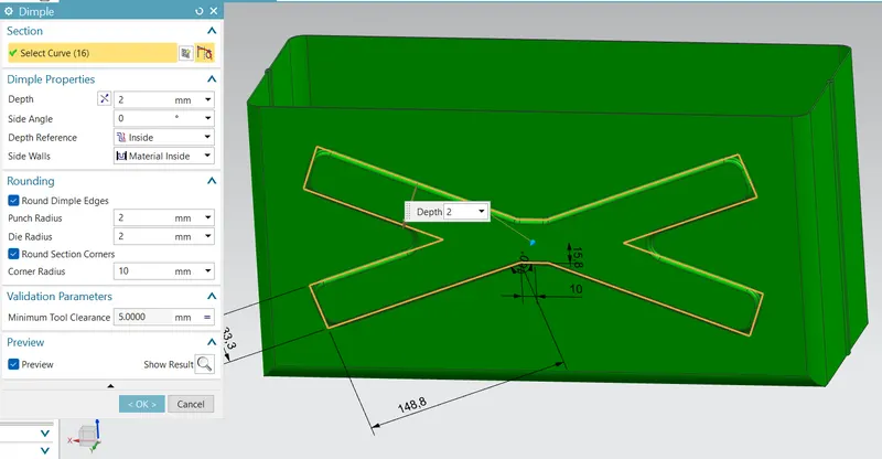
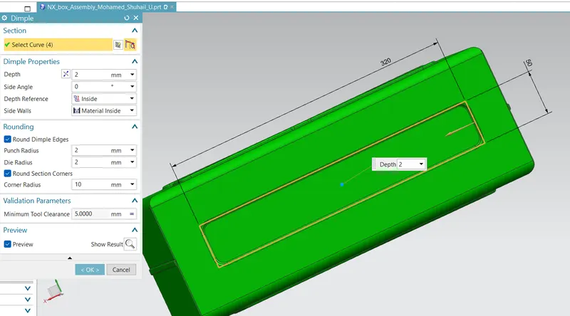
A couple of ‘Dimple’ is introduced on the walls and floor of the box. Dimples are added to improve the strongest feature of the structure, and also give an appealing design consider to the flat design.
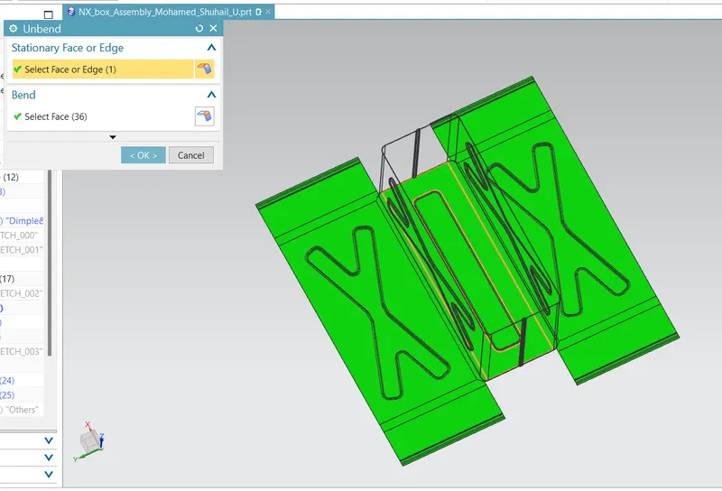
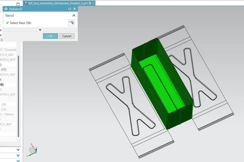
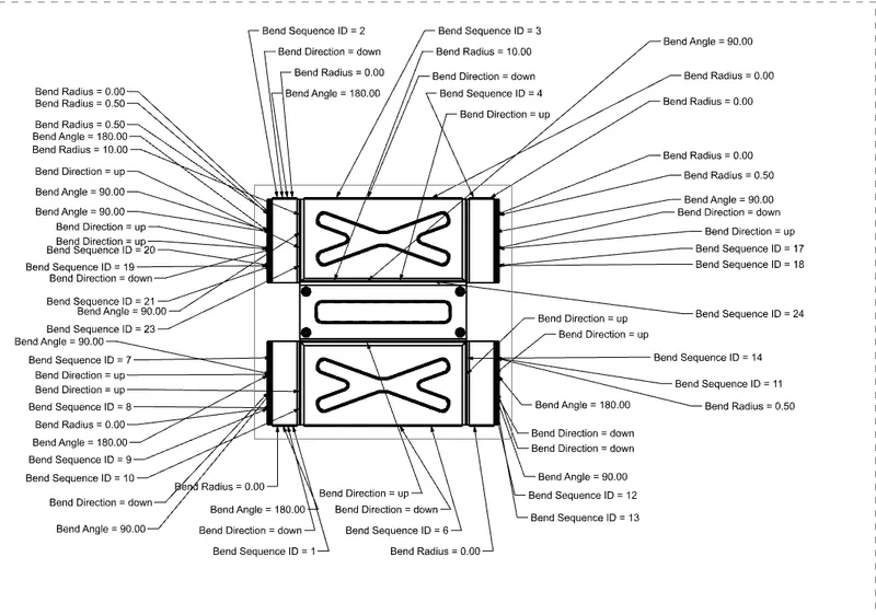
The ‘Unbend’ command is used to view the flat feature of the model, and is folded back using the ‘Re-bend’ command.
Beads are introduced on the bottom portion of the body using the command ‘Bead’, this acts as a leg for the box.
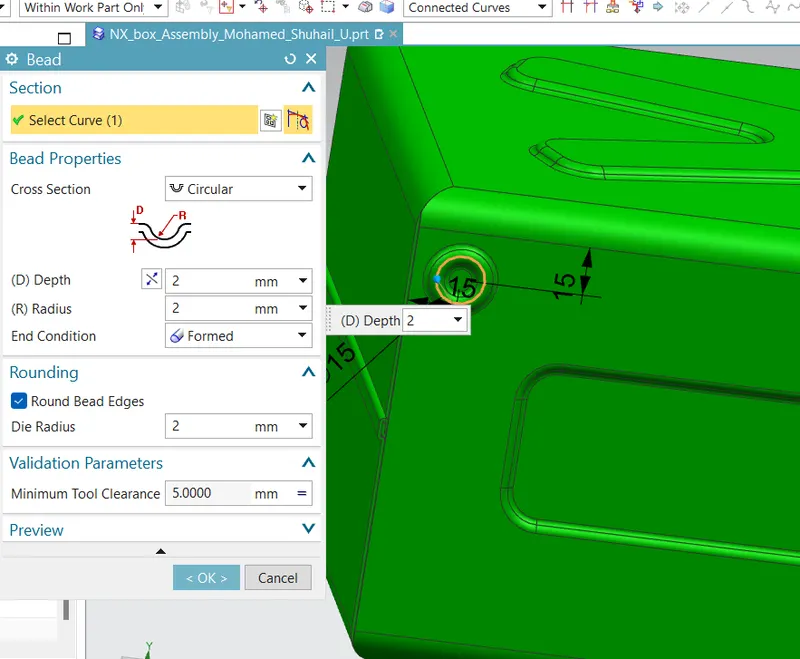
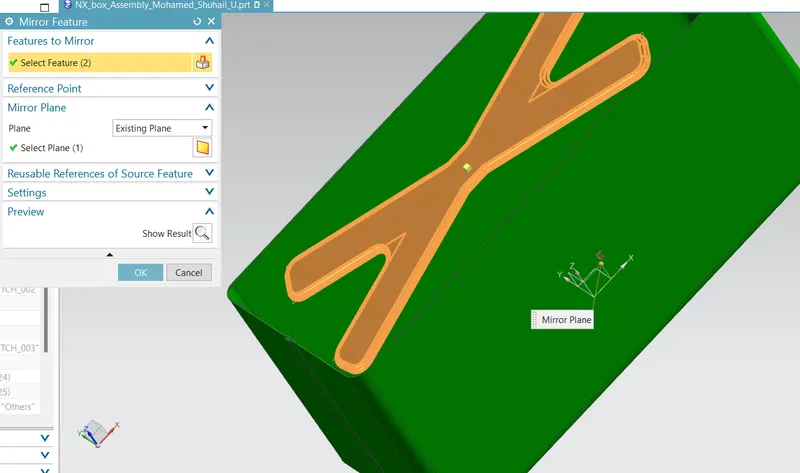
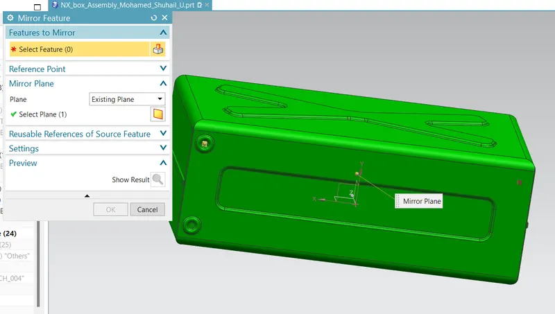
The mirror feature is used to copy the ‘Bead’ command, and the mirror command is used a couple of times to make 4 beads.
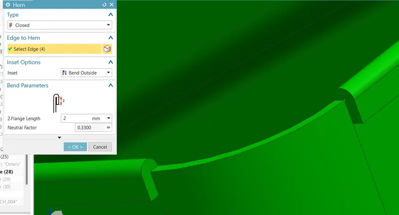
Finally, a closed-type hem is introduced on the top of the part to make the opening smooth.
Part – 2: Cap Modeling
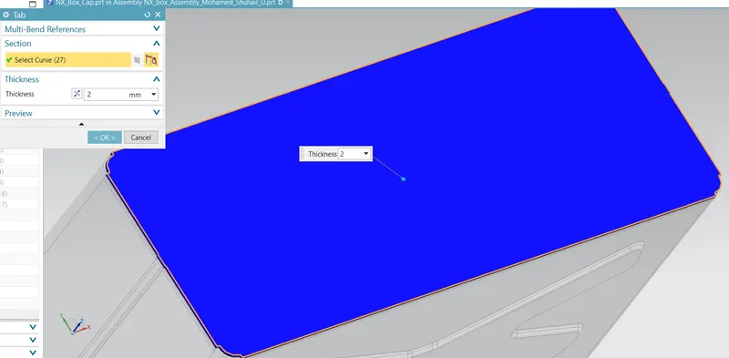
The sketch on the open portion of part -1 is used to make a tab feature, this part act as a cap to the box.
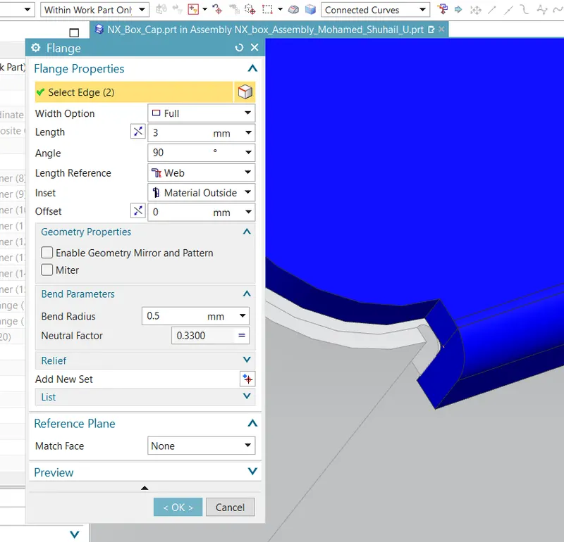
Multiple flanges are introduced to the tabbed model to make the cap appealing and fit.
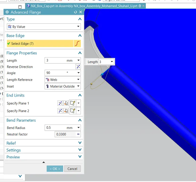
Part – 3: Hinge Part -1
To hold the cap over the box, a hinge is designed. This act as a door to give access to the box compartment.
The hinge is fixed on the side wall. The modeling process started with introducing a tab on the side wall.
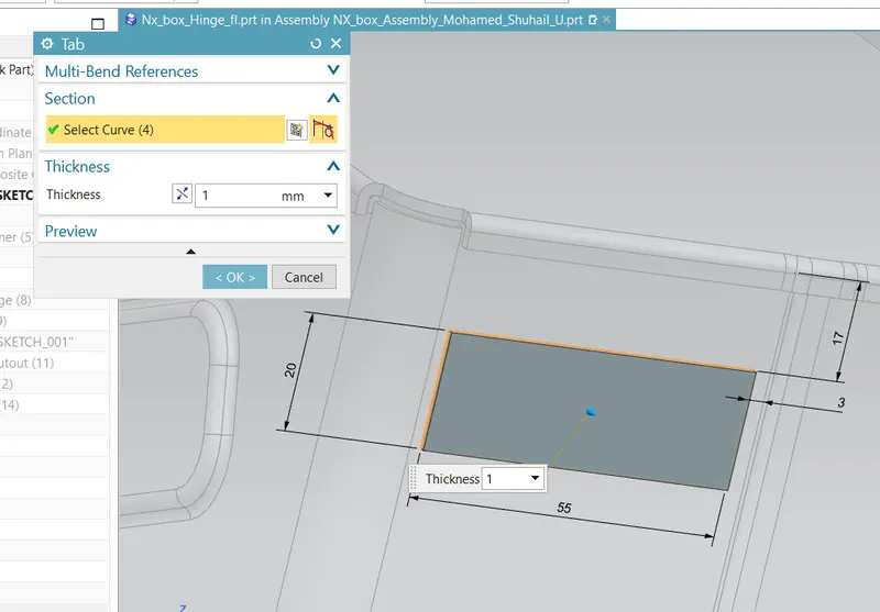
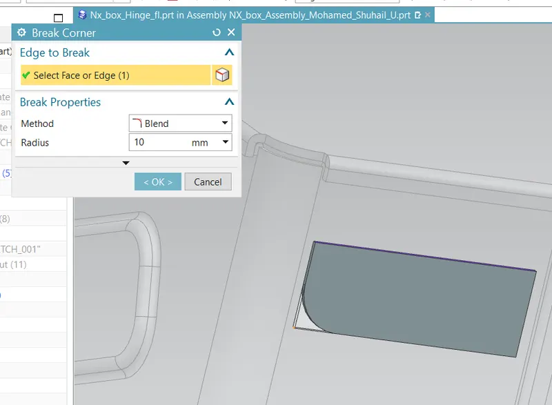
The corner is smoothened using the ‘Break Corner’ command.
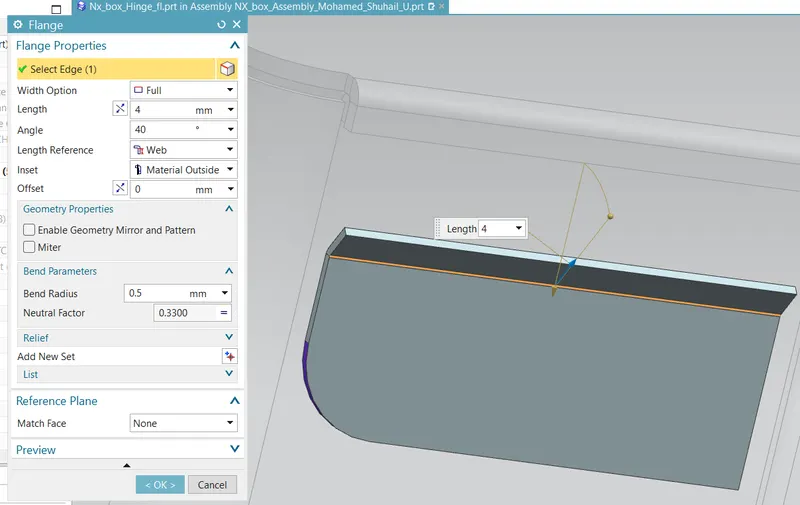
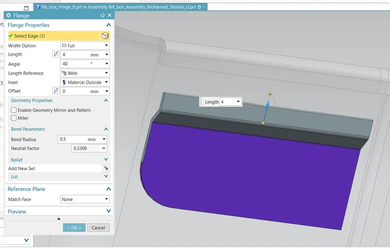
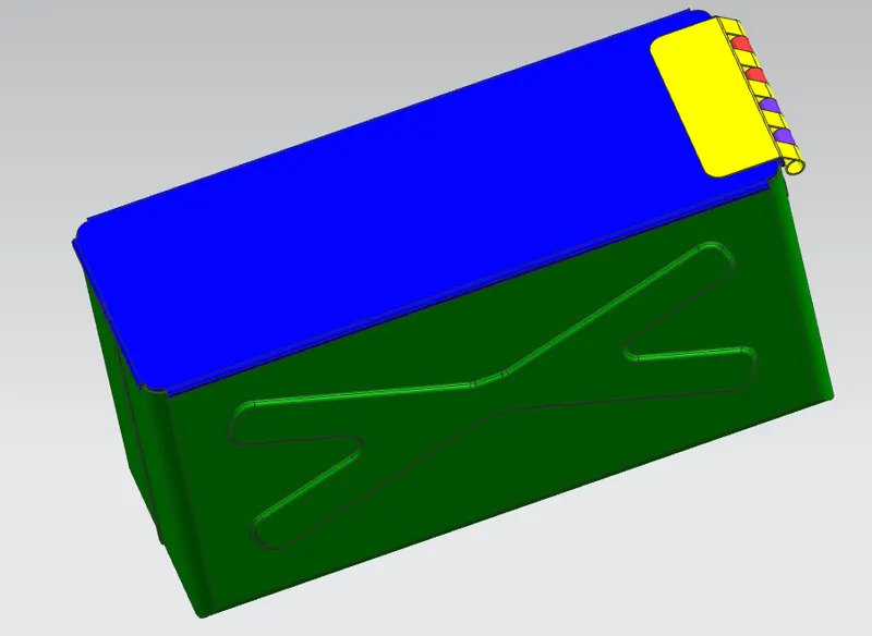
Multiple flanges are introduced to create a round lock on the box.
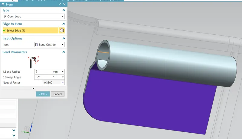
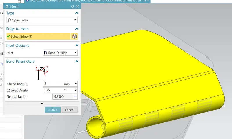
The hem feature is used to create a round feature, which acts as a lock system between the hinge components.
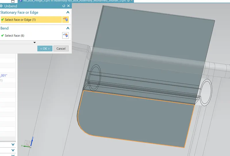
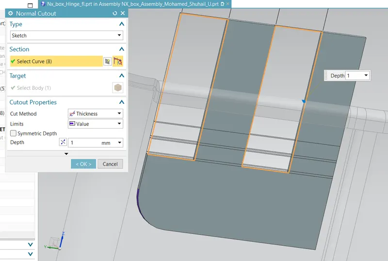
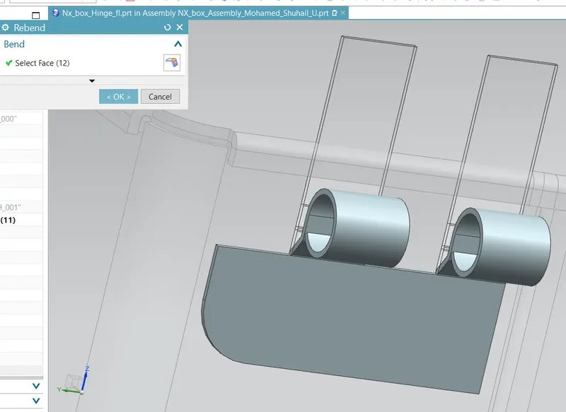
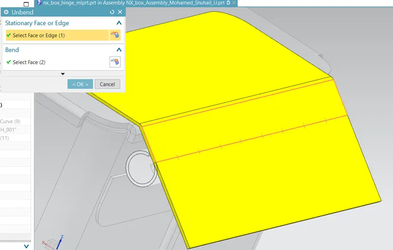
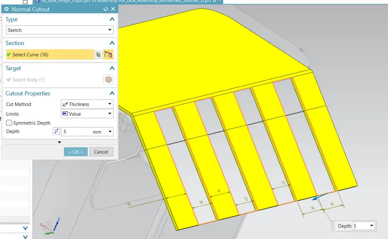
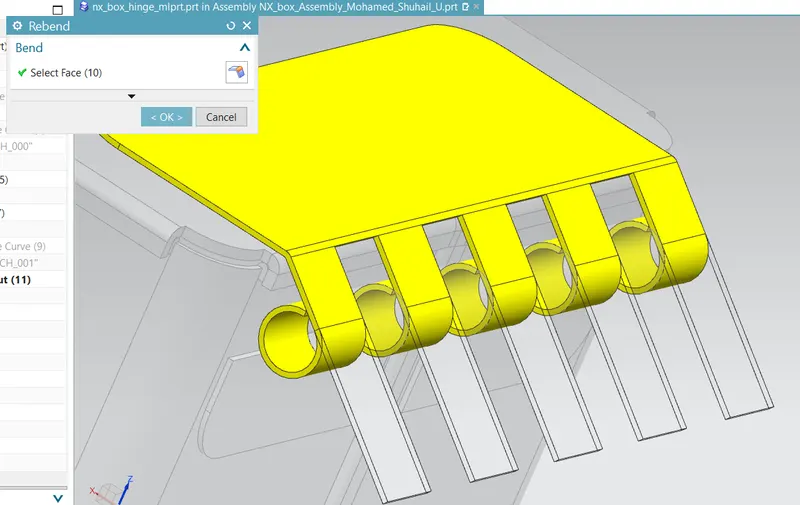
The model is flattened using the ‘Unbend’ command and a normal cutout is created on the model using the ‘Normal Cutout’ command. And finally, the structure is folded back using the ‘Rebend’ command.
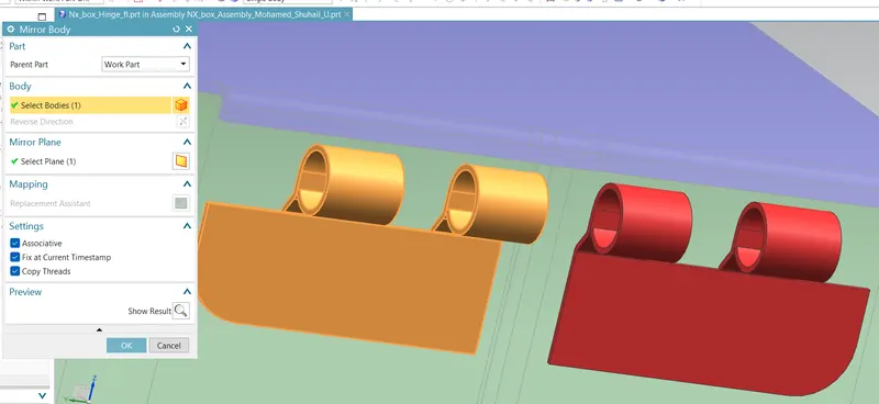
A mirror of the entire part is made using the ‘Mirror Body’ feature (Mirror assembly part can also be used.)
Part – 3: Hinge part -2
The part of the hinge that fixes on the cap is made using the previous hinge part as a reference.
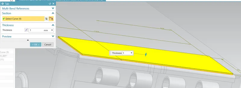
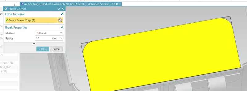
The modeling starts with a ‘Tab’ feature to create a sheet, and the corners are smoothened using the ‘Break Corner’ command.
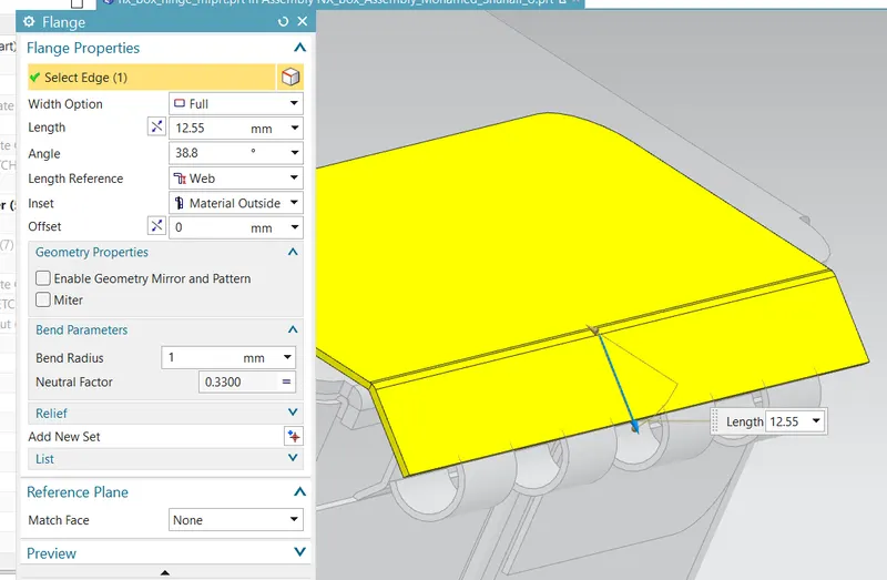
A flange is made on the tab.
The hem has introduced the model to make the lock structure.
The structure is flattened using the ‘Unbend’ command and cut out portions using ‘Normal Cutout’ and finally folded back using the ‘Rebend’ command.
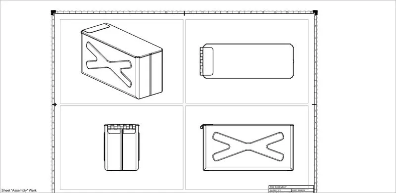
Final Views
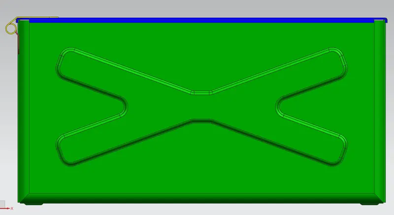
Front View
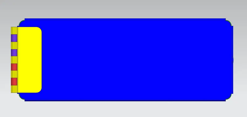
Top View
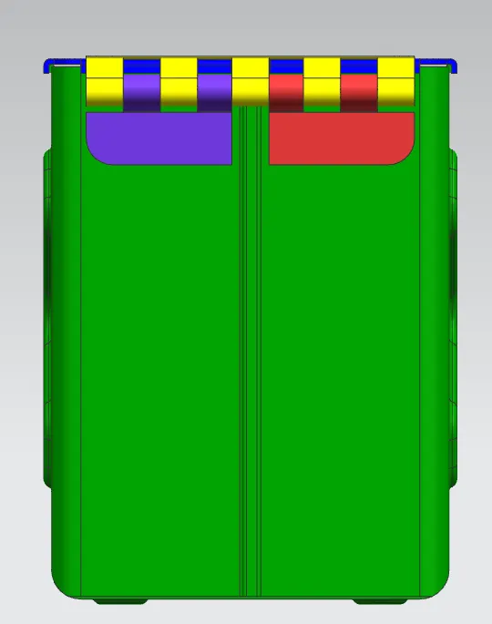
Side View
Isometric View
Drawings
Main Body
Assembly