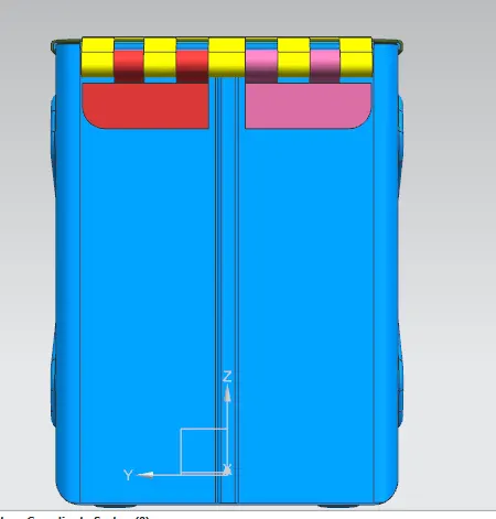
Advanced Sheet Metal Design Using NX Cad Challenge_2_Box Assembly
TITLE:
Design of sheet metal box assembly using NX-CAD
OBJECTIVE:
To design the sheet metal box assembly using NX-CAD and also draft the flattened sheet metal design.
INTRODUCTION:
Sheet metal is a flat or thin shaped metal which is leaned to a sheet and it has a thickness of 0.5-6 mm. Using sheet metal, we can create any sorts of designs like case, holes, dies, punches and several other forms. Unlike other materials it is easy to bend, rebend, drilled and to carry also. It is used in places like AC, Automobile body parts, computer, machineries, tray and etc.
Flowchart:
- Base and cutout
- Bend
- Flanges and holes
- Unbend
- Embose
- Rebend
- Drafting
PROCEDURE:
1. Create base and cutout
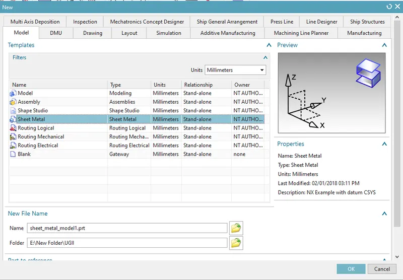
- create new sheet metal file and open the sketch option from direct sketch tab and select the XY plane, specify the horizontal vector as X vector and specify the part origin.
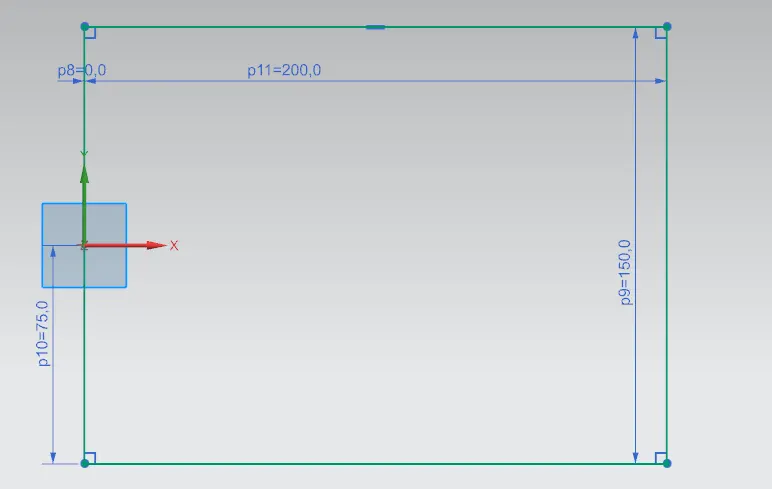
- Draw a rectangle with dimensions 200 mm in length and 150 mm in width on XY plane at origin (0,0,0).
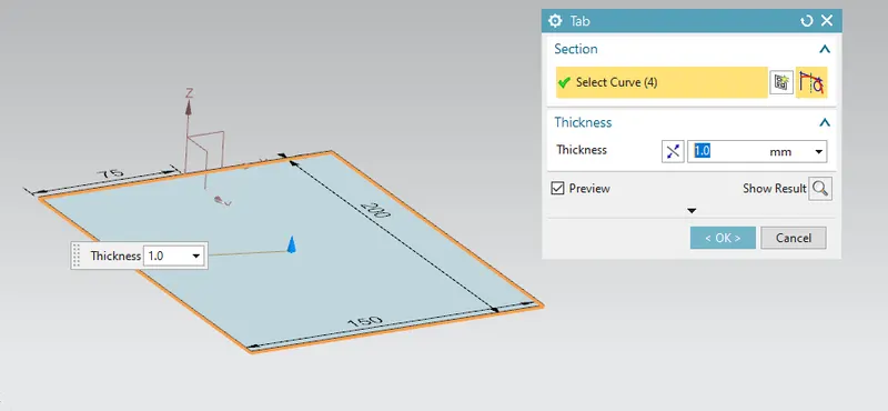
- Modulate the skecth into sheet by selecting the tab option from basic tab and choose the lines, enter the thickness value as 1 mm.
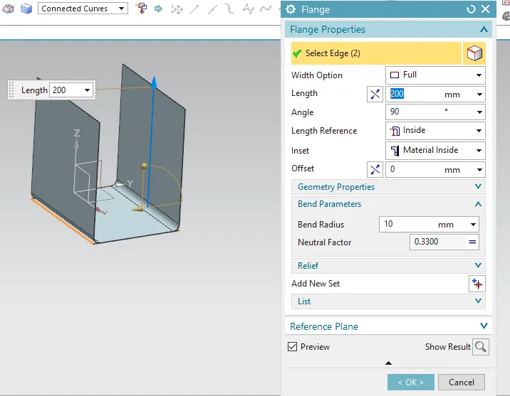
- Create flanges from bend tab, select the edges and enter the input values as length 200 mm, angle 90 mm, inset as material inside and bend radius as 10 mm.
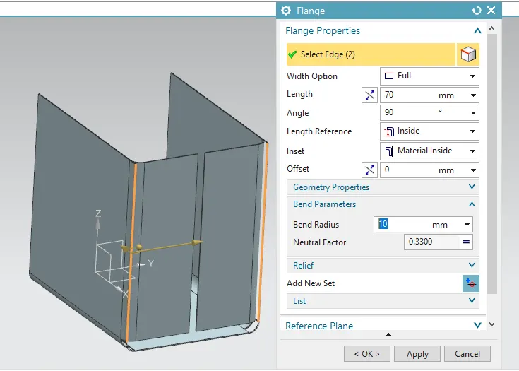
- Also create flanges on side flange, select the edges and enter the input values as length 70 mm, angle 90 mm, inset as material inside and bend radius as 10 mm.
- Ensure the corner relief as none. Click the black triangle > relief > corner relief > none.
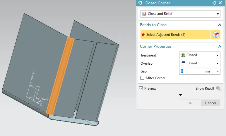
- Select the edges and enter closed corner command from corner tab with overlap closed and gap as 0 mm.
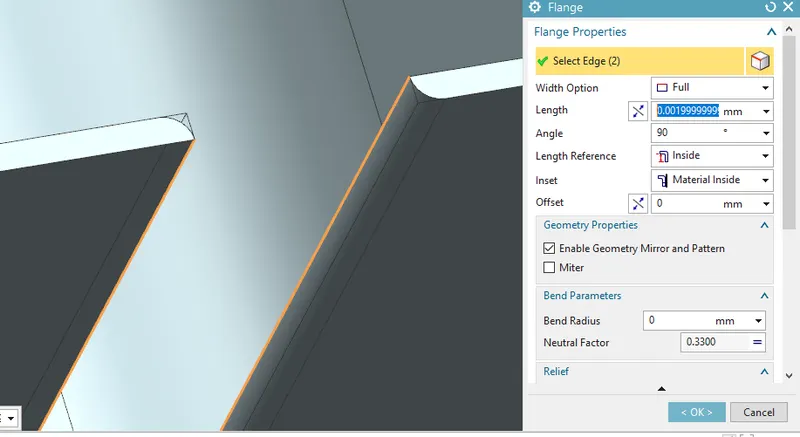
- Create flanges from bend tab, select the edges and enter the input values as length 0.002 mm, angle 90 mm, inset as material inside and bend radius as 10 mm.
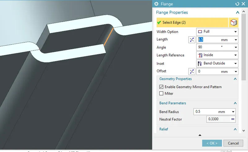
- Create flanges to make two sheet metal to be locked inside, by entering inputs length 6.5 mm, angle 90 mm, inset as bend inside and bend radius as 0.5 mm.
- Use hem option from bend tab> more> hem flange and enter open hem, bend radius 0.5 mm, Flange length 5 mm.
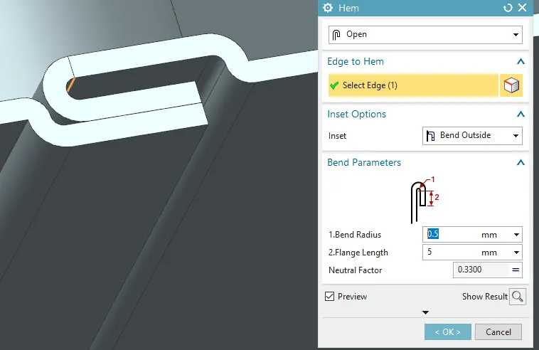
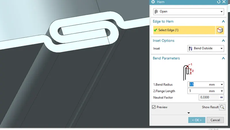
- Follow the same procedure from hem.
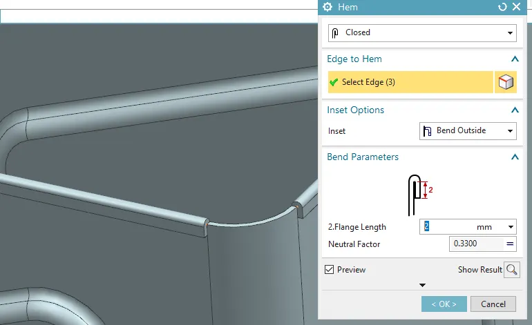
- Use hem option for the top outer bodies expect rounded edges, hemmed parts and select edges,enter closed hem, inset as bend outside and Flange length 5 mm.
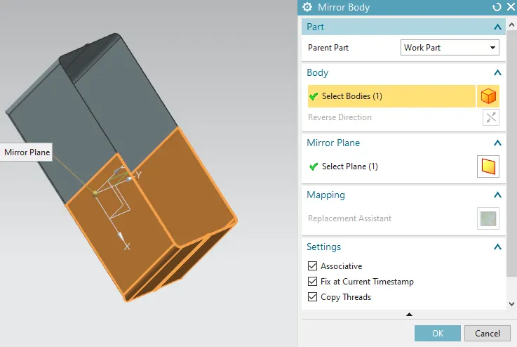
- Mirror the sheet by yz plane as reference using Feature tab>more>mirror feature.
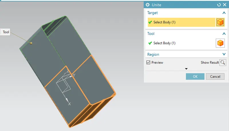
- Unite both the sheet bodies together.
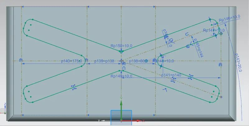
- Create dimple as cross symbol in center of design on sides using sketch command from direct sketch tab with sides R10 mm.
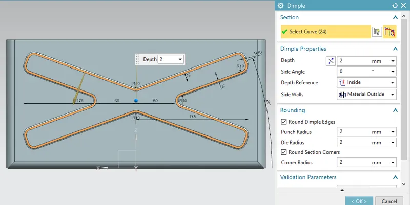
- Use dimple option to create embosement in sheet for 2 mm in depth, Depth reference as inside, side walls as material outside.
- Mirror the dimple by XZ plane as reference using Feature tab>more>mirror feature.
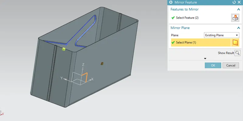
- Create dimple as rectangle in center of design at bottom using sketch command from direct sketch tab with sides R10 mm and other dimensions by refering the cross.
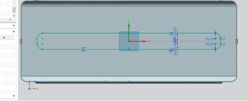
- Use dimple option to create embosement in sheet for 2 mm in depth, Depth reference as inside, side walls as material outside.

- Unbend the 3D sheet metal design to flattened sheet metal, by using unbend command from form tab and select the edges and adjacent faces.
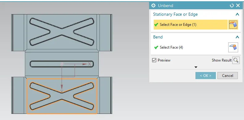
6. Rebend the flat sheet to 3D sheet
- Use rebend command to return the flattened sheet to 3D sheet design from rebend command in form tab by selecting the bend and flanges orderwise.
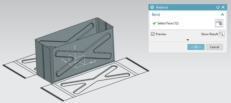
- Create circular embose surrounding the rectangle in bottom by using direct sketch tab>sketch>circle with dimensions as 15 mm diameter, 7.5 mm away from outer sides.
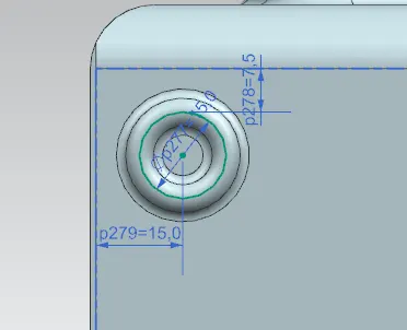
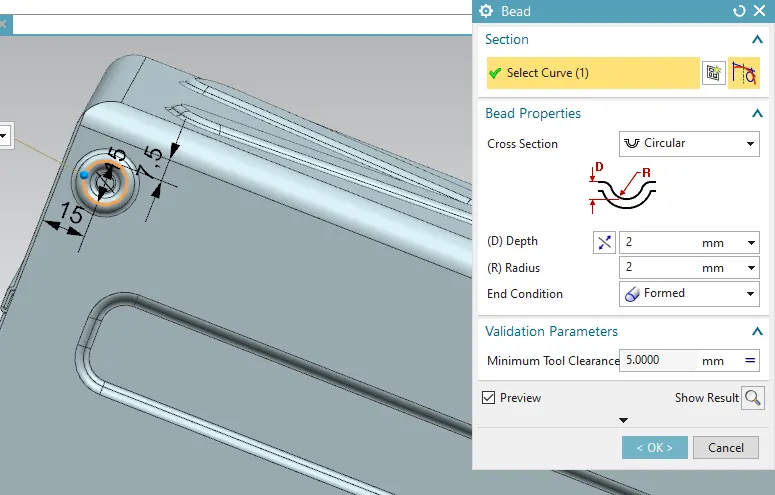
- Use bead option from punch tab, to create a circular embose for 2 mm in depth, 2 mm in radius, end condition as formed.
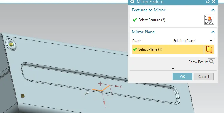
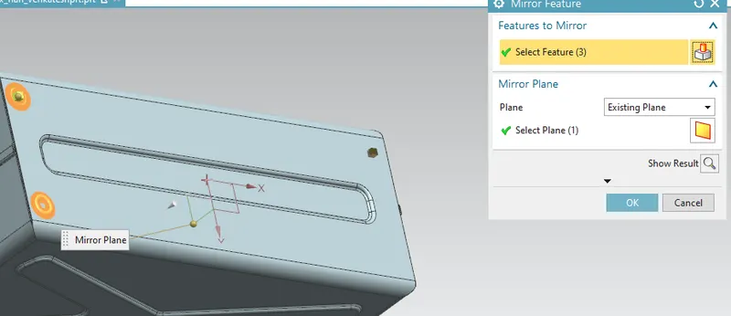
- Mirror the circular embose by X vector as reference using Feature tab>more>mirror feature and also use both the circular emboses to mirror it along Y vector.
- Create a datum plane for 202 mm.
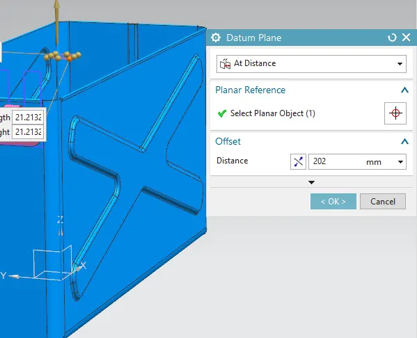
- Refering the top section and its flanges, hems. Create a sketch of a sheet enclosing the box.
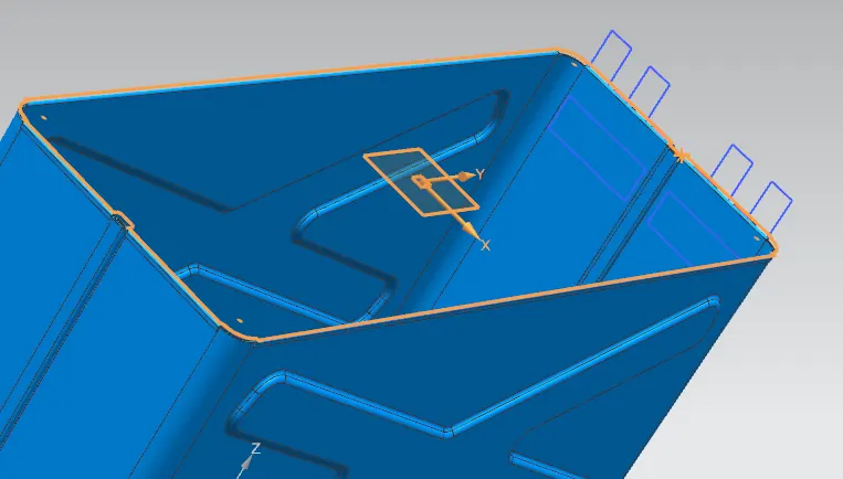
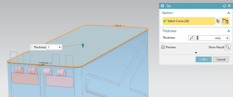
- Modulate the skecth into sheet by selecting the tab option from basic tab and choose the lines, enter the thickness value as 1 mm.
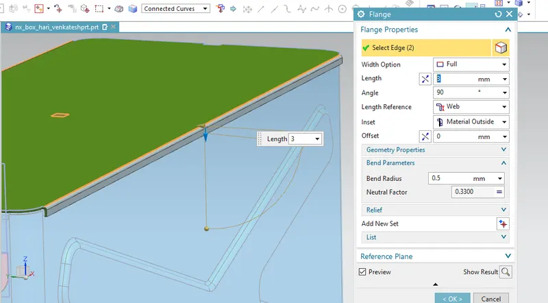
- Create flange on lateral sides from bend tab, select the edges and enter the input values as length 3 mm, angle 90 mm, length reference as web, inset as material outside and bend radius as 0.5 mm.
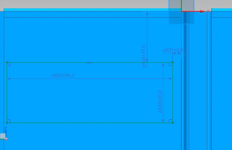
- Create rectangular sketch using sketch command from direct sketch tab with 55 mm in length and 20 mm in width on one side of box away from 17 mm on X and 3 mm on Y.
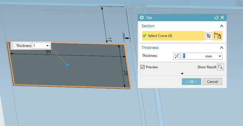
- Modulate the skecth into sheet by selecting the tab option from basic tab and choose the lines, enter the thickness value as 1 mm.
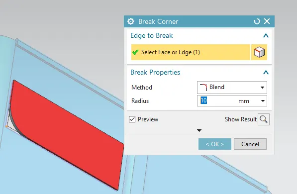
- The tab has sharp edges use break corner from corner tab and radius value as 10 mm.
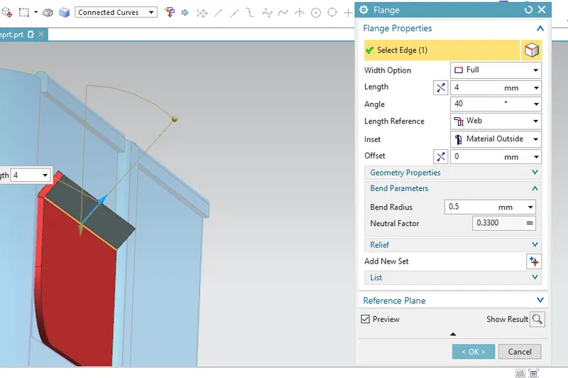
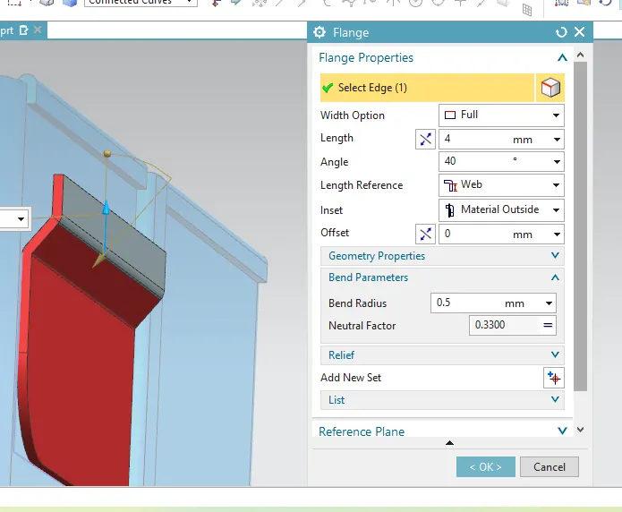
- Create flanges from bend tab, select the edges and enter the input values as length 4 mm, angle 40 mm, length reference as web, inset as material outside and bend radius as 0.5 mm.
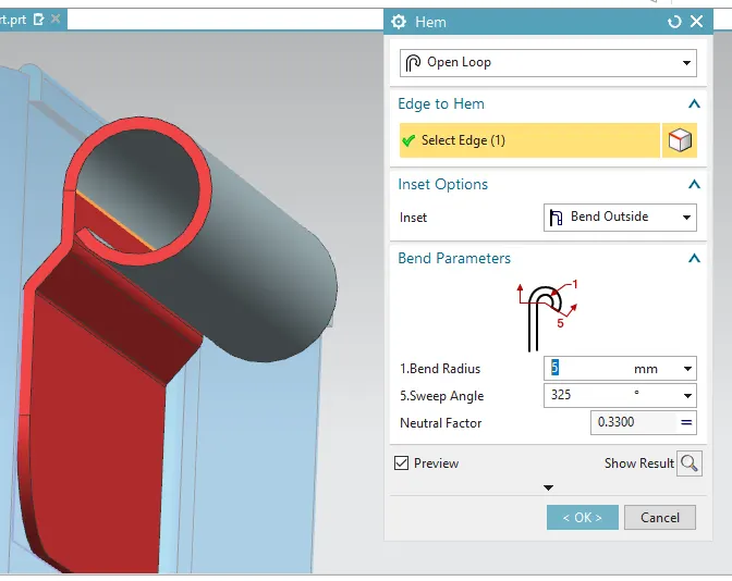
- Use hem option select edges,enter open loop hem, inset as bend outside, Flange length 5 mm and swept angle 325 degree.
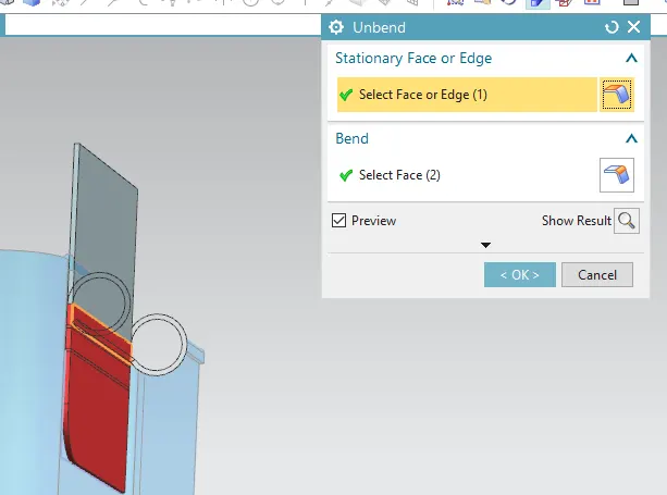
- Unbend the 3D sheet metal design to flattened sheet metal, by using unbend command from form tab and select the edges and adjacent faces.
- Create sketch of two rectangle for 14 mm length, 40 mm width for a distance of 14 mm.
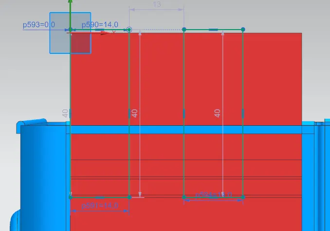
- Modulate the rectangular sketch by choosing the normal cutout command on feature tab and enter the value as 5 mm depth and cut method as thickness.
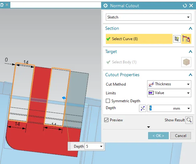
- Use rebend command to return the flattened sheet to 3D sheet design from rebend command in form tab by selecting the bend and flanges orderwise.
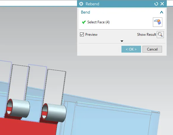
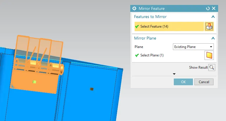
- Mirror the assembly loop by z vector as reference using Feature tab>more>mirror feature.
- Create rectangular sketch using sketch command from direct sketch tab with 126mm in length and 40 mm in width nearer to the edge refering assembly loop of box.
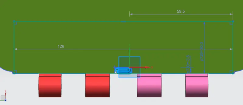
- Modulate the skecth into sheet by selecting the tab option from basic tab and choose the lines, enter the thickness value as 1 mm.
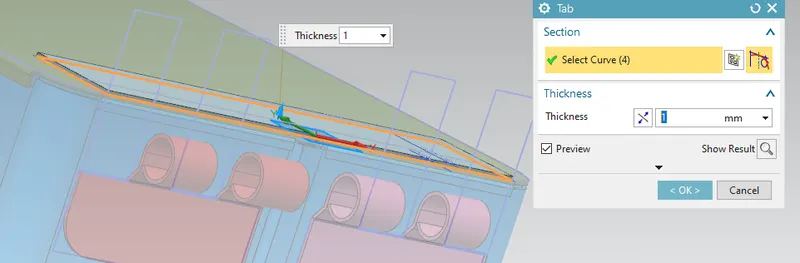
- The tab has sharp edges use break corner from corner tab and radius value as 10 mm.
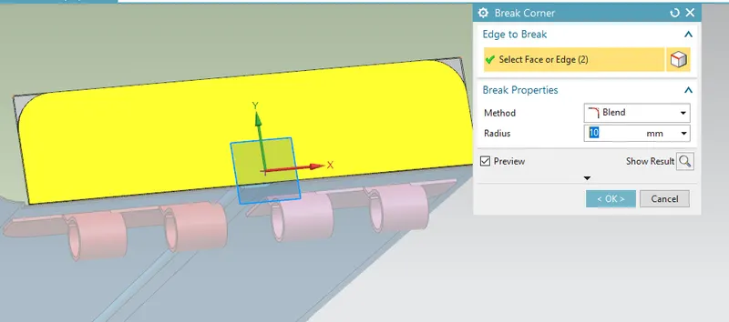
- Create flanges from bend tab, select the edges and enter the input values as length 11.65 mm, angle 35 mm, length reference as web, inset as material outside and bend radius as 1 mm. [Note: if the above dimensions doesn't match use the length, angle and bend radius value as `+-5` accordingly]
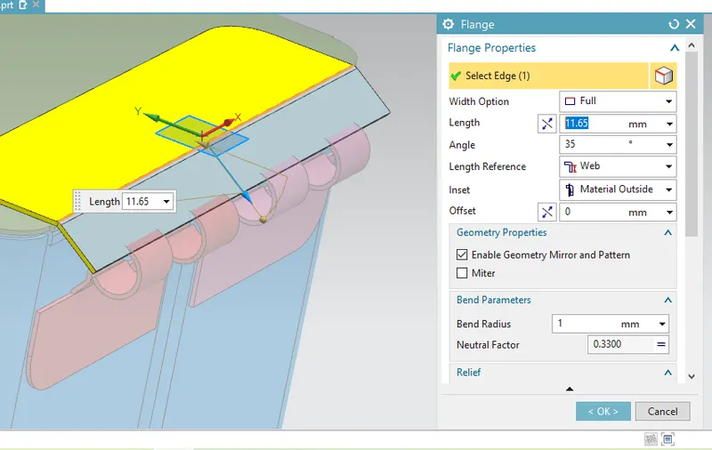
- Use hem option select edges,enter open loop hem, inset as bend outside, Flange length 5 mm and swept angle 325 degree.
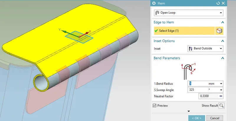
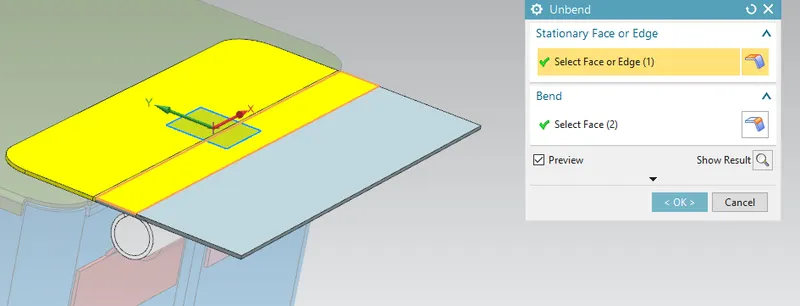
- Unbend the 3D sheet metal design to flattened sheet metal, by using unbend command from form tab and select the edges and adjacent faces.
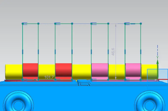
- Create sketch of two rectangle for 14 mm length, 40 mm width for a distance of 14 mm.
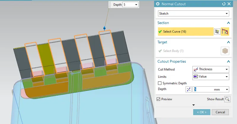
- Modulate the rectangular sketch by choosing the normal cutout command on feature tab and enter the value as 5 mm depth and cut method as thickness.
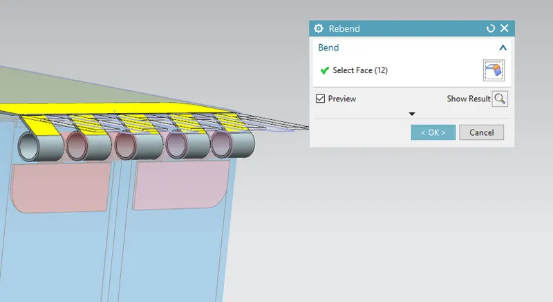
- Use rebend command to return the flattened sheet to 3D sheet design from rebend command in form tab by selecting the bend and flanges orderwise.
RESULT:
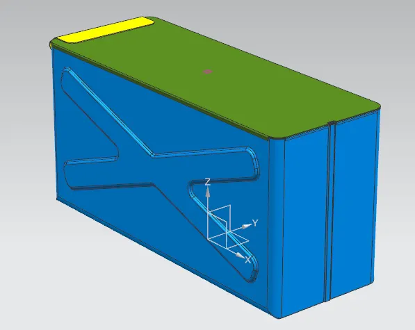
- Isometric view
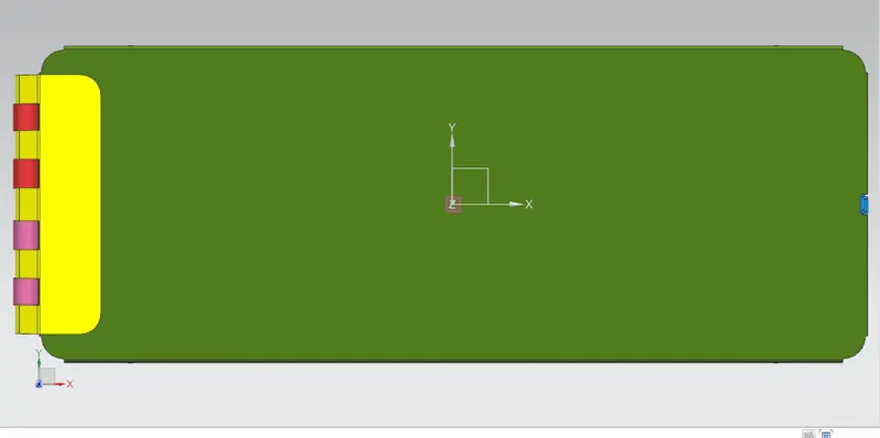
- Top view
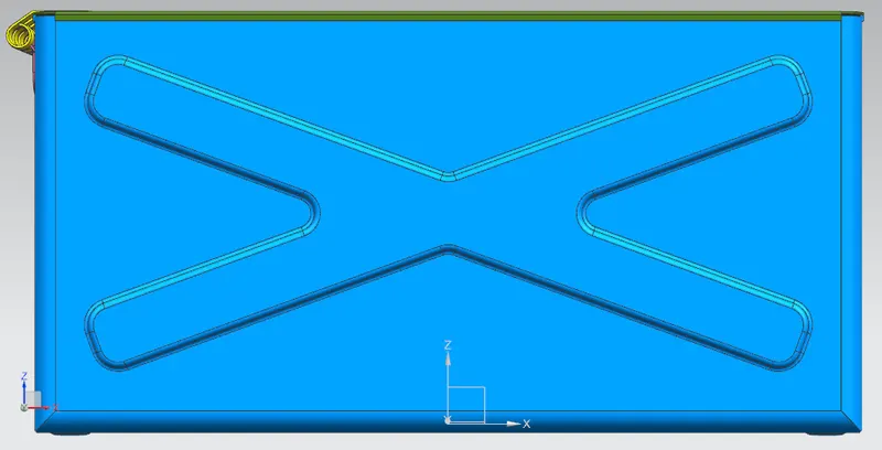
- Front view
- Sideview