Advanced Sheet Metal Design Using NX Cad Challenge_2_Box Assembly
Title of the Project:- To design the Box Assembly and Perform Operation tool on sheet metel using in NX CAD Software.
Objective:-
- The main objective what is the Sheet Metal Basics in this project and the lern about fundamental and advance tools of NX CAD.
- In this project I have Design the Box Assembly and Apply various tool operation on it.
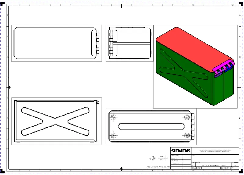
- To Created 2D detailed Drawing sheet.
Introduction:-
NX is formerly known as UG (Unigraphics), as high-end software owned by owned by Siemens PLM since 2007.High-end software means it is an advanced level CAD/CAM/CAE software package developed by Siemens PLM.
Likewise other CAD software, NX-CAD also provide the same purpose of designing or modelling a new part,Drafting (Drawing),Assemnly etc.NX adapts iser-frindly environment, furthe more. it is also delivers onnovative technologies for maximum productivity and creativity from the nasic concept to the final product.NX allows flexibility in the use of feature-based and parametric design.
In addition to creating solid model, Sheet metal and assemblies, the 2D drawing view can also be generated easily in the Drafting environment of NX.
The drawing aspects that can be made include orthographic,section,auxiliary,isometric and detail view.The model dimensions and reference dimensions in the drawing in the drawing view can be produced.
NX provided the benifits that any modifications made in the model are reflected in the drawing aspect automatically can create sketches directly in the Modeling environment.
The software has powerful modeling capabilities by integrating constraint-based feature modeling and geometric modeling.In addition to modeling standard geometry parts.It allows the use to design complex free-form shapes such as airfoils and manifolds.
NX is Used for:-
1] Solid Medelling/Design (Parsmetric and direct solid/surface medelling).
2] Design sheet metal components.
3] Manufacturing design by using included machining modules.
Design methodology:-
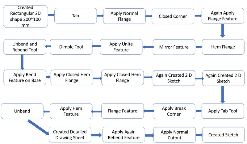
Design Methodology Description:-
- First We have start the NX 12 Software and create a sheet metal part. Create a sketches in the XY plane and draw the rectangular cetered at original give the Dimensions X-length of 200 mm and a y-length of 150 mm.then the sketches is extruded using the tab feature.
- Tab Tool:- This feature is used to create a extrude a sketches to a given thickness . It is also used for to add the material on the existing tab.
- Flanges:- Flange feature is used to create a bend at a angle and upto the a given lenght.
- Closed Corner:- Use closed corner tool to close the corners with adjacent flanges. Use the flange, hem flange tools to fold and stiffen the edges at the middle.
- Hem Flange:- command to modify an edge of a sheet metal part by folding it onto itself for the purpose of safe handling or to increase edge stiffness.
- Mirror Body:- Use the Mirror Body command to mirror an entire body across a datum plane.
- Unite:- Unite command use to combine the volume of two or more solid bodies into a single body.
- Dimple :- The Dimple command makes an indentation in the sheet metal part, using a sketched section as its outline. The difference between the two is that a Dimple feature has a bottom face whereas a Drawn Cutout feature does not.
- Bending:- The bending feature is used to the bend the sheet from the given line in the sheet at a 90 angle.
- Normal Cutout:- The Normal cutout is used for the remove the material from the given sheet and with respect to sketch.
- After we have go to Breaking corner feature.Then the bend is created at the corners with the help of cornor breakout.
- Cornor Breakout:- The Cornor Breakout feature is used to break the sharp edges of the cornor with the help of various shapes. In this model we have used circular bend of the give radius.
- Then the click on Unbend tool. Selected as Stationary face and large horizontal face of the metel sheet next select the as bend face on of its.
- Unbend :- The unbend tool is used to unbend the bended tool of sheet metal.
- Rebend:- Use the Rebend commands to unbend and rebend non-uniform thickness bends.
- Drafting:- Quickly and easily create engineering drawings from 3D models using highly efficient drafting tools. The drafting software automatically creates drawing views from 3D part and assembly models, and helps you align and scale drawing views and arrange drawing sheets.
Final Box Assembly:-
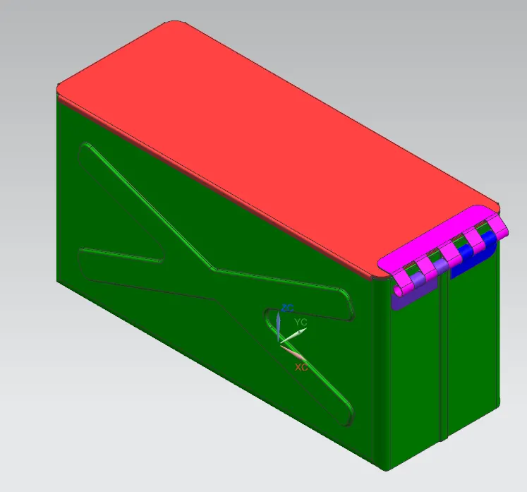
Model View (Front View, Side View, Isometric View and the Top View):-
Front View:-
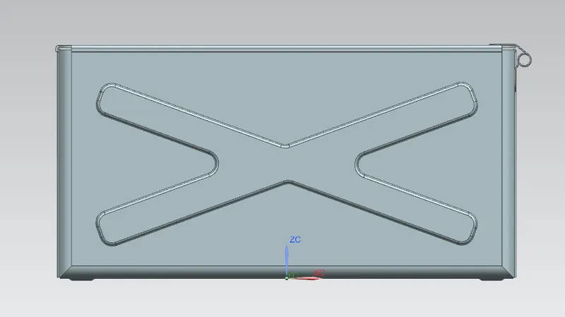
Side View:-
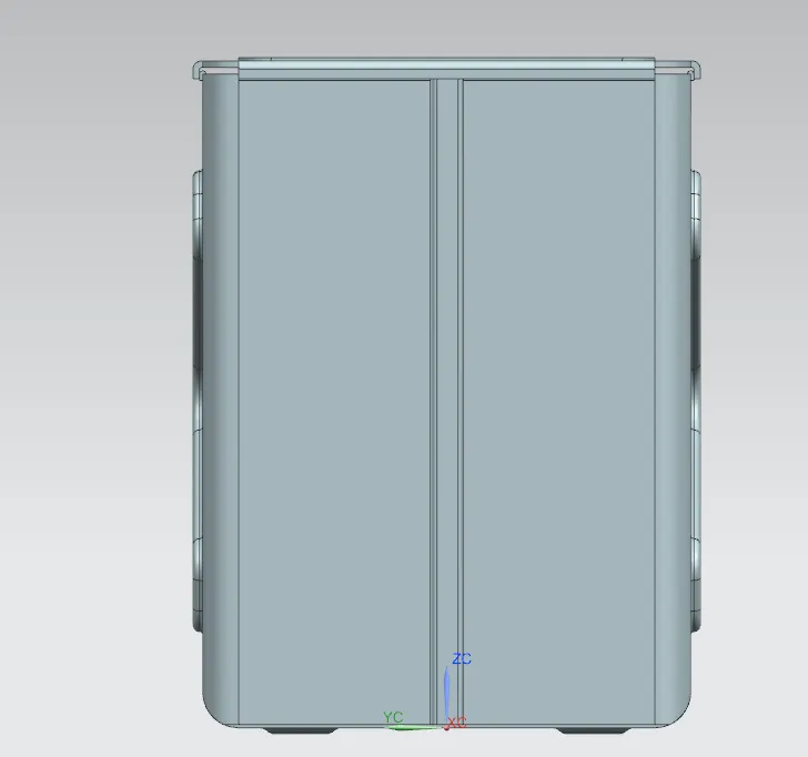
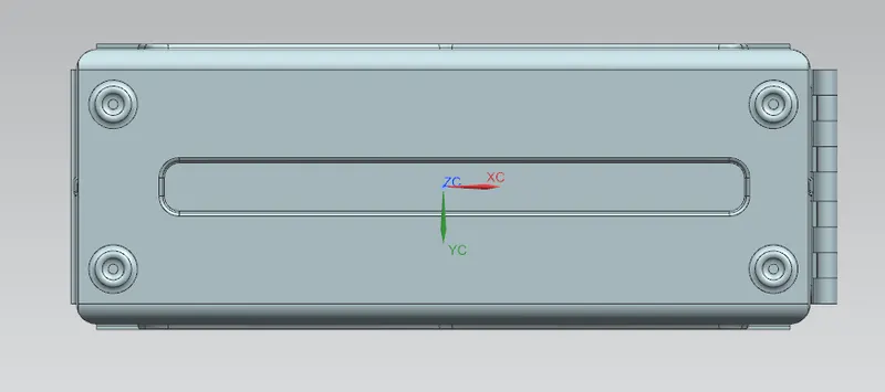
Bottom View:-
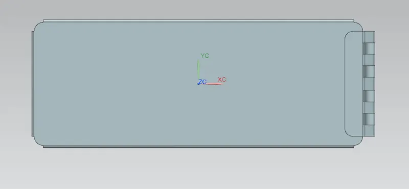
Top View:-
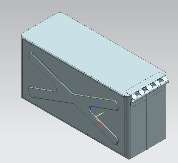
Isometric View:-
Detailed Drawing Sheet:-
Conclusion:-
In this project I have create Box Assembly Design done. I have learned about the various basics and advanced tool commmand of NX CAD sheet metal. I have used are various command and perform on sheet metal on created for part like, Tab, Flanges, Bending and Undending Command, Bend , Adding Dimple , Simple Flange, Hem Flange, Normal Cutout, and Making the 3 D part into 2 D skeches.