Advanced Sheet Metal Design Using NX Cad Challenge_1_Casing Design
Title of the Project - Advanced Sheet Metal Design Using NX CAD challenge 1 - Casing
Objective
To design a casing using NX CAD.
Introduction
Any metal having a thickness in between 0 to 6 mm is called a sheet metal. Sheet metal is a metal formed by industrial such as hot and cold press into thin and flat pieces. It can be cut and bend into many shapes. Here we design a casing using NX CAD software.
Design Methodology
Description
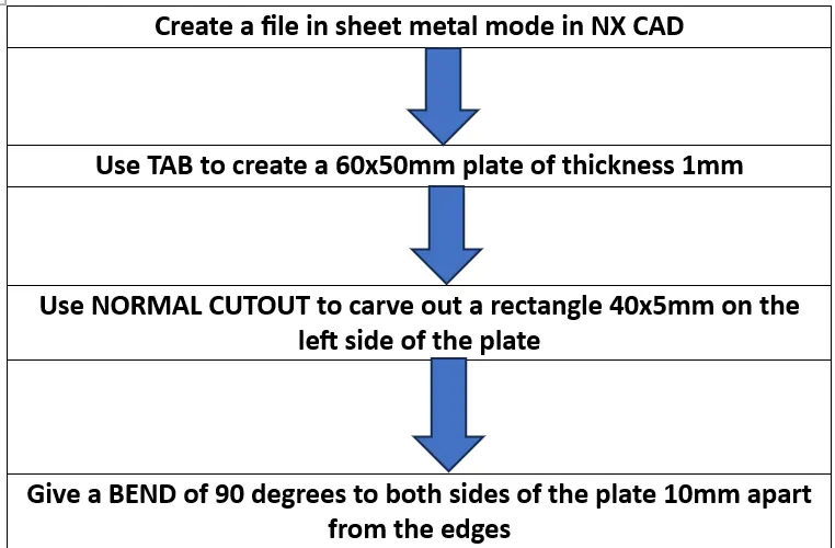
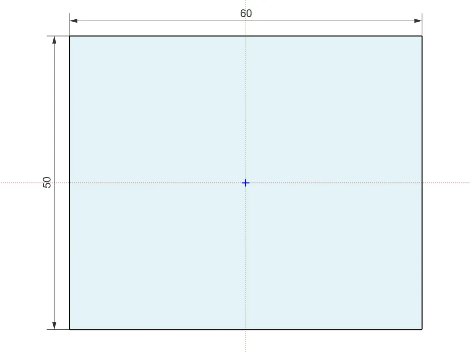
1. Open NX CAD and select new and select sheet metal. Open sketch and select a plane (xy) and draw a rectangle of 60mm length and 50 mm height. Then exit the sketch.
2. TAB
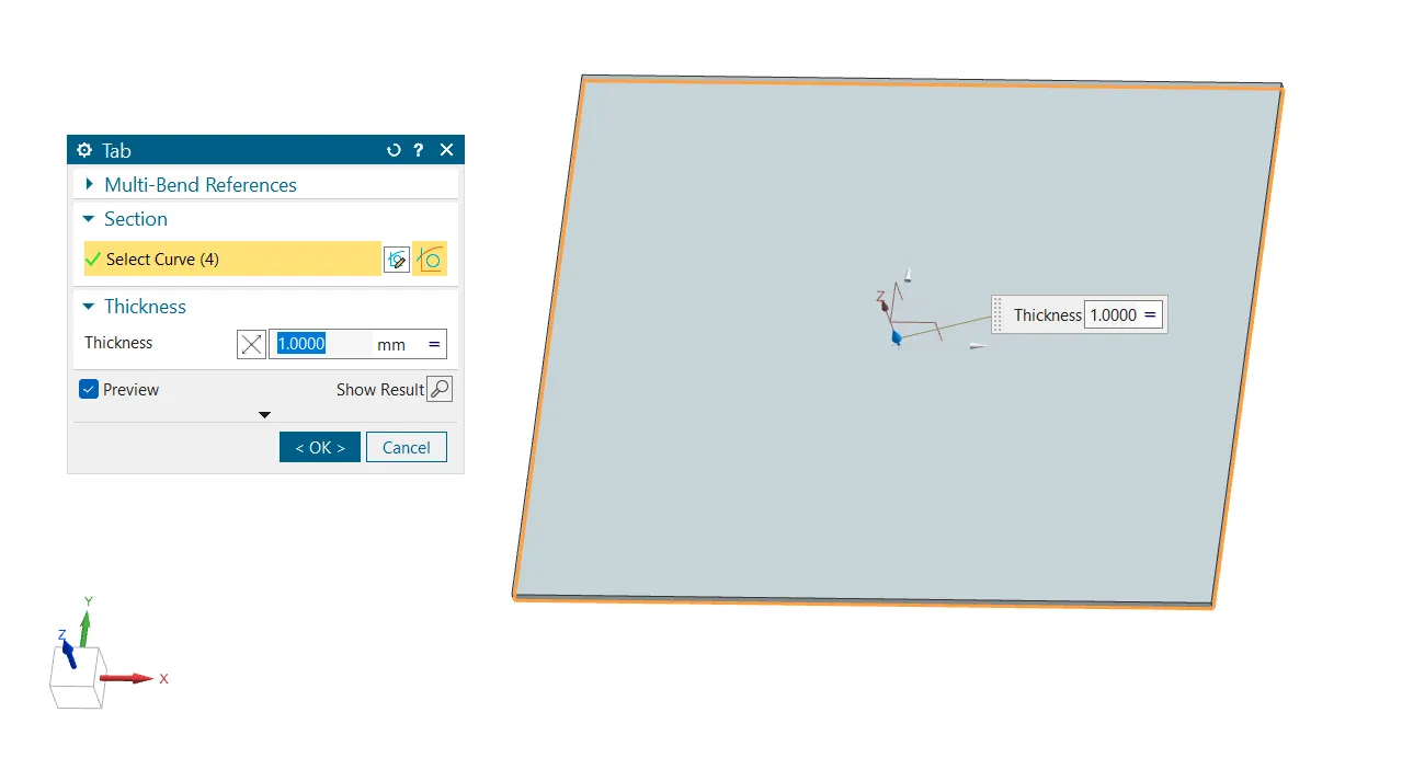
Then we use the command tab. It creates a base feature by extruding a sketch along a vector by a thickness value or adds material to a planar face.
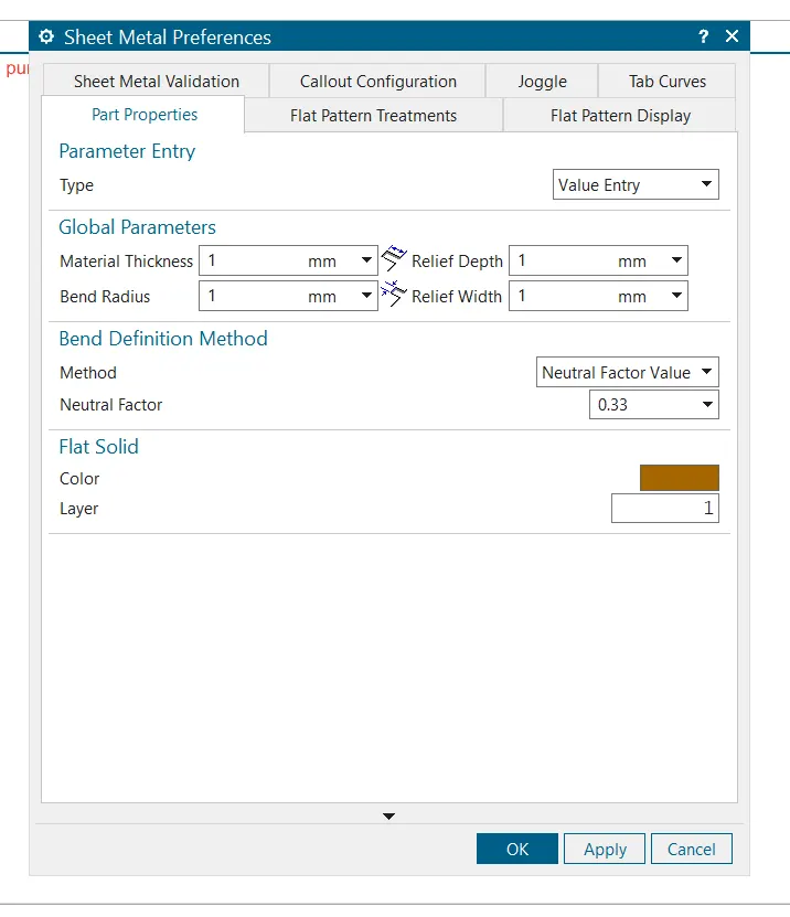
But before we apply tab, we change the design parameters by opening preferences and setting all the four parameters to 1mm.
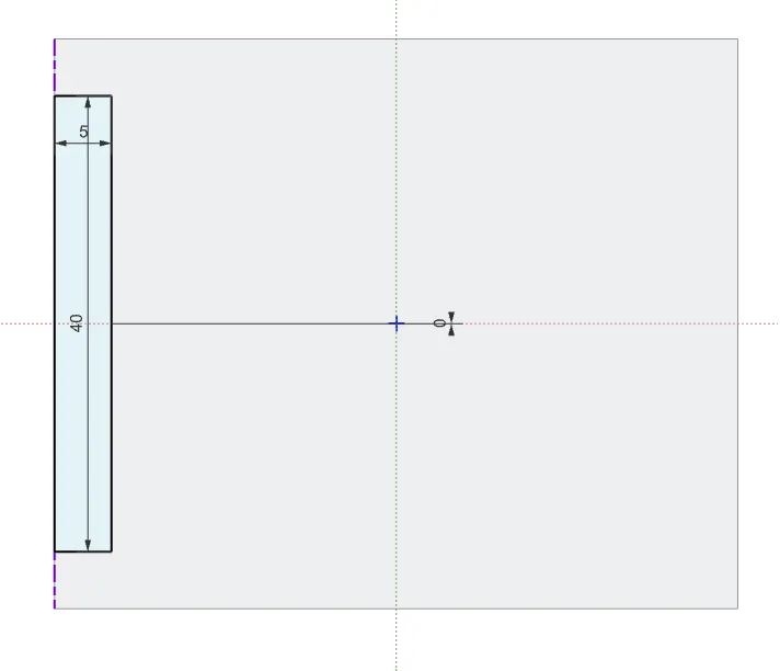
3. Again select sketch menu and draw a rectangle of size 5mm wide and 40mm long symmetric with x axis which is coincident with the left edge of the rectangle.
4. NORMAL CUTOUT
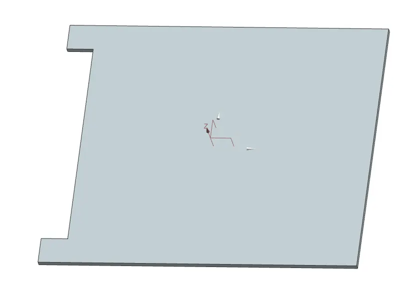
It cuts the material by projecting a sketch onto the model and then cutting perpendicular to the faces intersected by the projection.
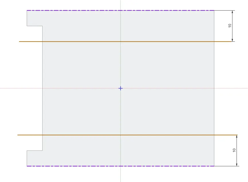
5. Again we draw a sketch in the top plane consisting of two symmetric horizondal lines with respect to x - axis. Both these lines are located 10 mm away from the upper left and lower left corner of the metal sheet.
6. BEND
Click the bend button and select one line as bend line with an angle of 90 degrees. Repeat the same steps for the other line. 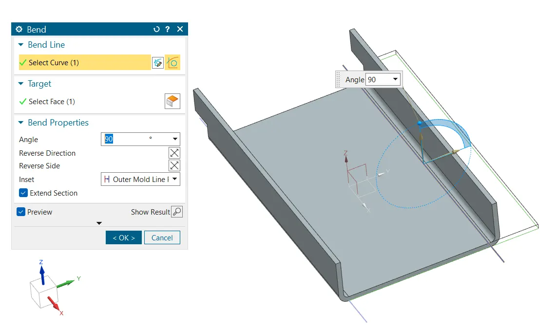
7. FLANGE
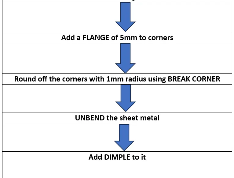
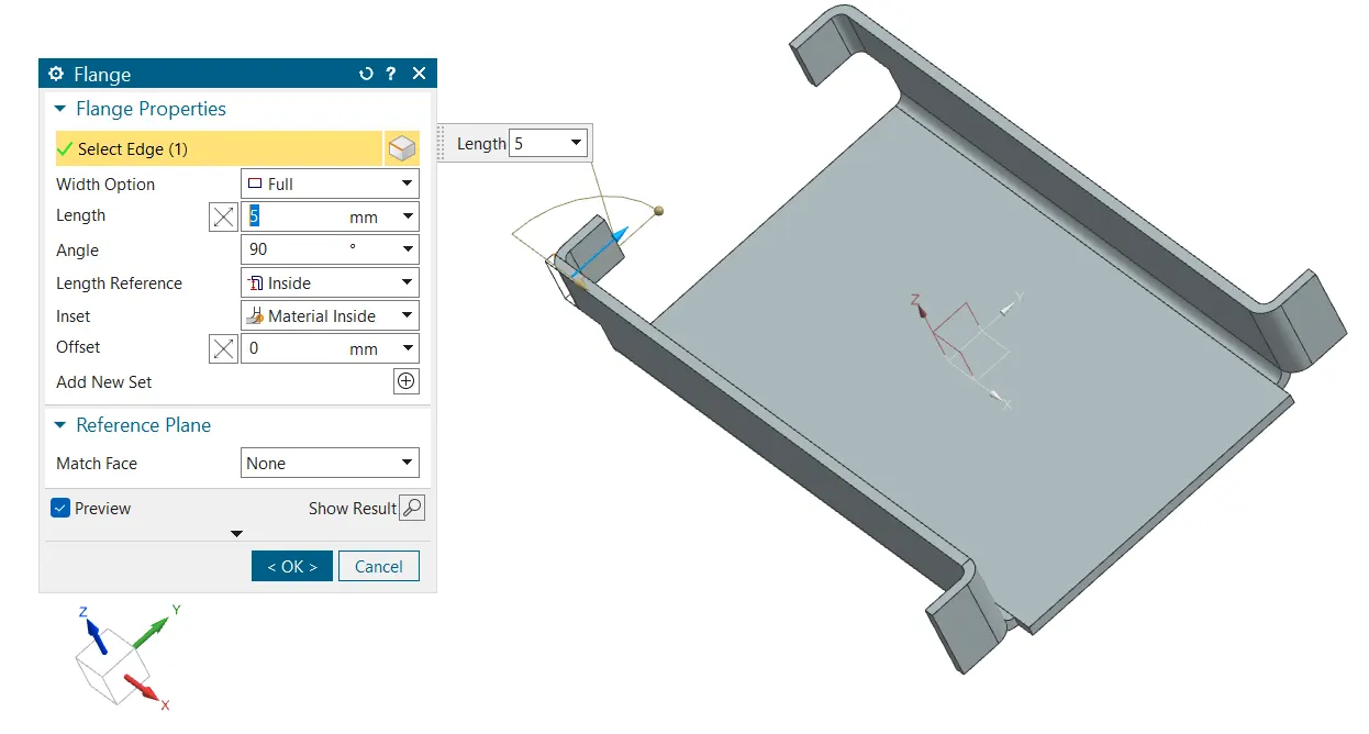
Click on the flange button and apply flanges of 5mm to the mentioned edges.
8. BREAK CORNER
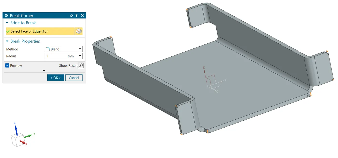
Use break corner button and select all the edges and use blend method with a radius of 1mm. It rounds a shrp edge.
9. UNBEND
It flattens every bend we created. Select on the unbend button and select the face and select the bends to unbend them.
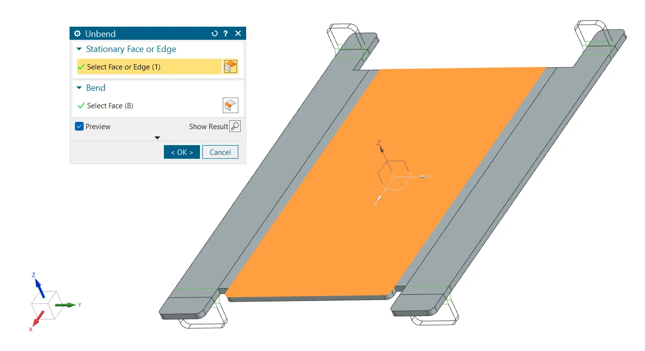
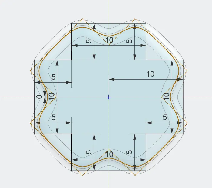
9. STUDIO SPLINE and MOVE CURVE
In the xy plane, we create the given sketch with each sides being 5mm. Then we use studio spline button, we select the type as 'by poles' and then we check the closed option. Then we select all the 16 points one by one in a single direction and click ok.
Click the move curve button and select the spline we created. Set the motion option of the transform field to angle. Specify the orgin as axis point and select the angle as 45 degree.
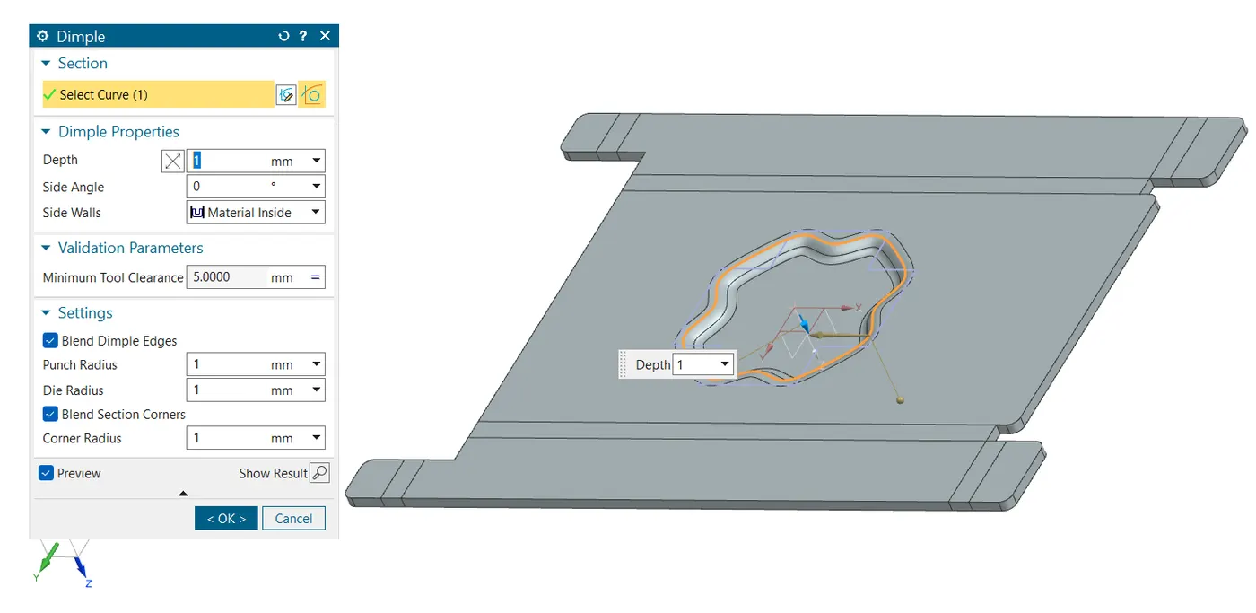
10. DIMPLE
Dimple in the sheet metal component provides more strength and rigidity to the flat structure of the component.
Select the curve and set the depth, punch radius, die radius, and corner radius all to 1mm and click ok.
11. To design a bead, first we sketch a circle of 5mm in diameter as shown in figure.
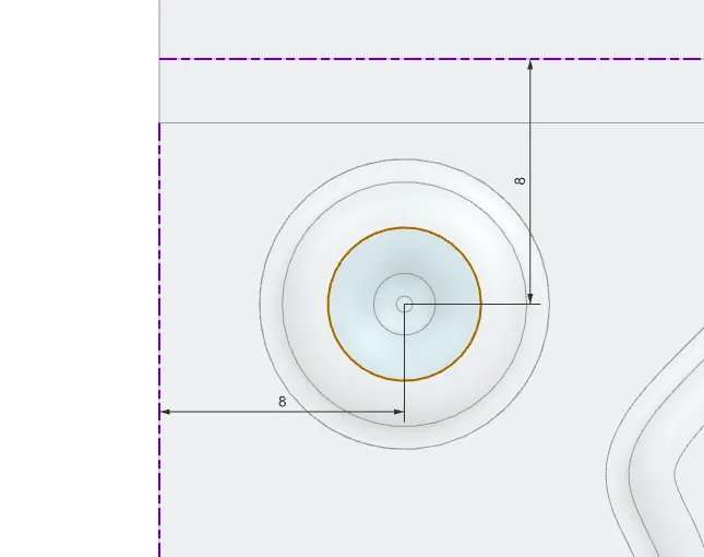
12. BEADS
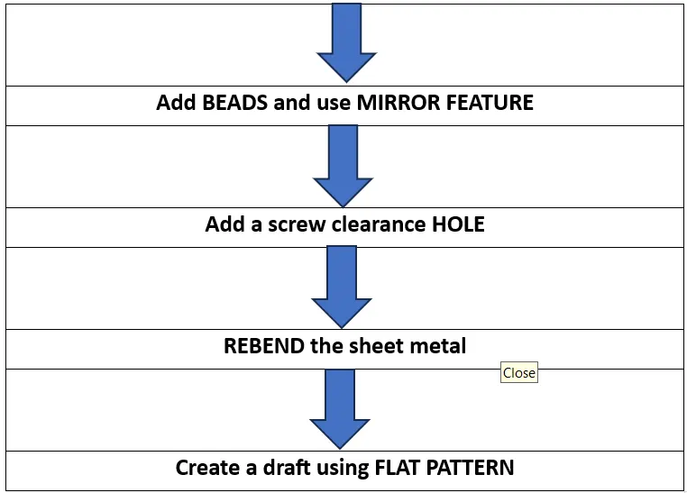
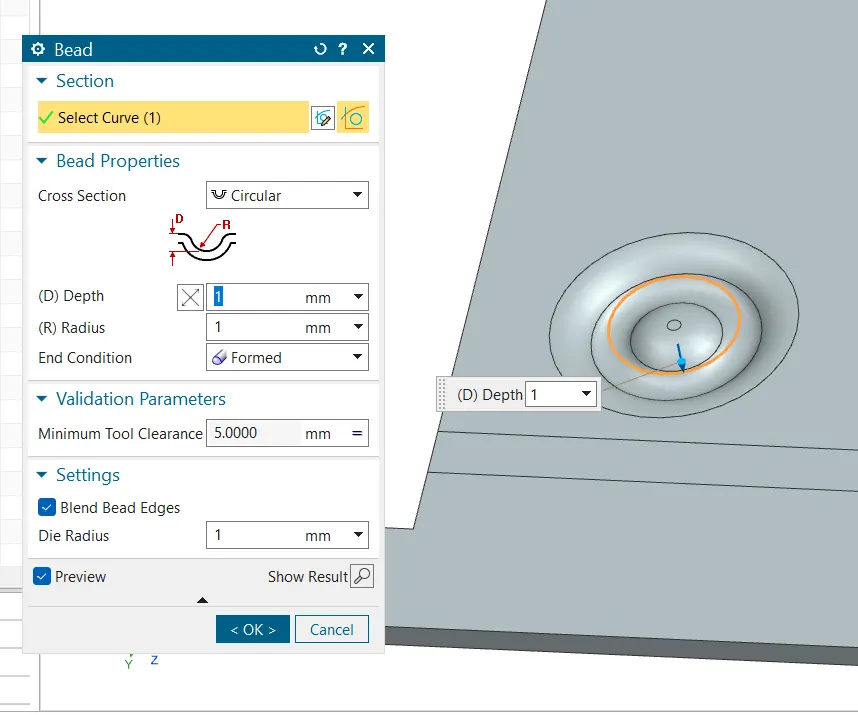
Click on the bead button and set every parameter to 1mm with a circular cross section and select the curve and click ok.
12. MIRROR FEATURE
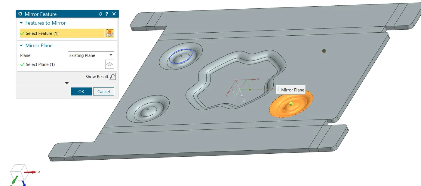
Click on the mirror feature button, and then select the YZ plane and Beads and thier corresponding sketches and click ok. Redo the same thing using xy plane
13. HOLES
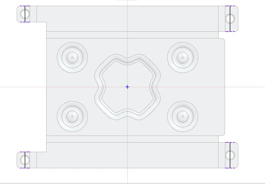
Draw a sketch for a hole
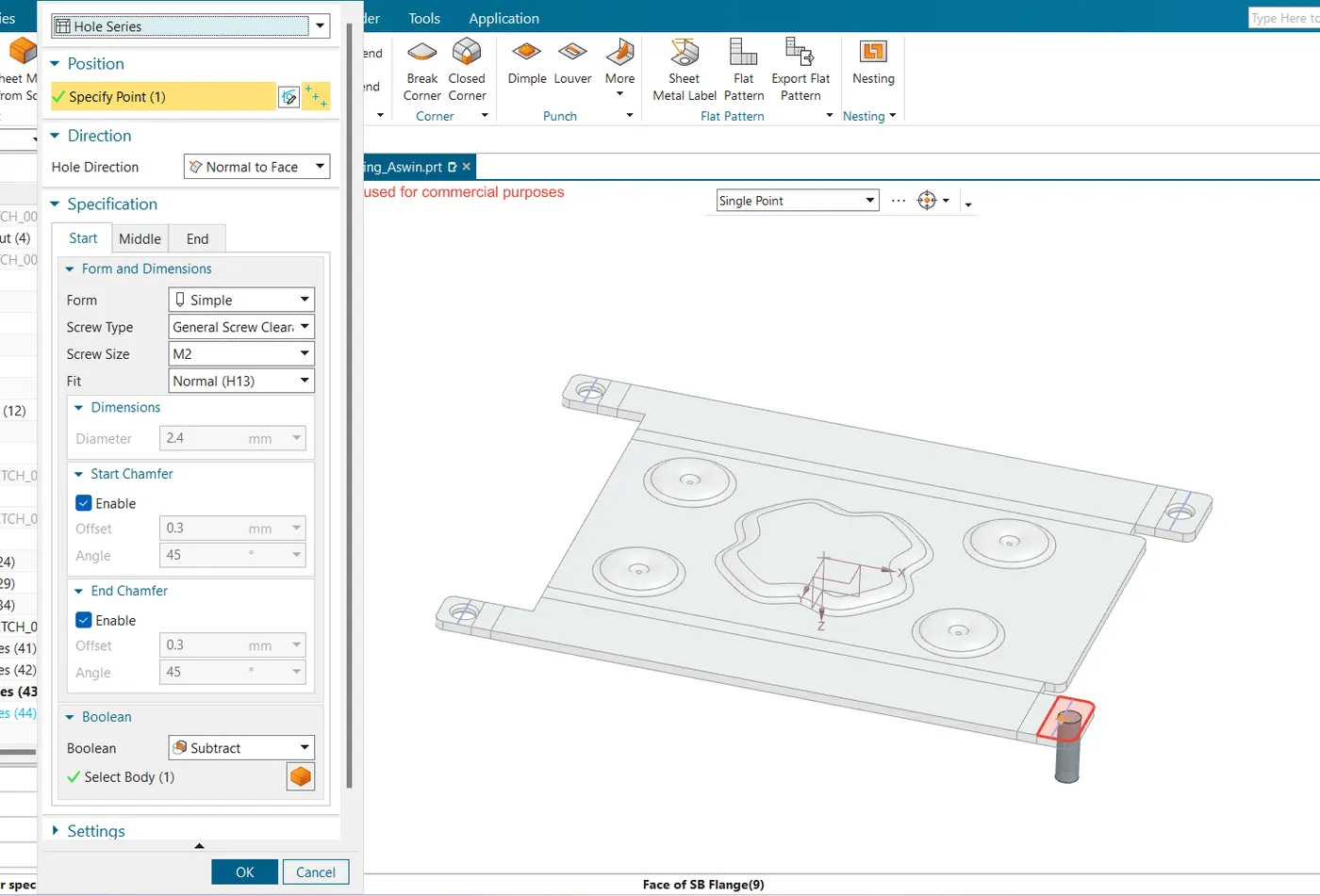
Select hole option, select hole series, specify the point and select the screw size as M2 and click ok.
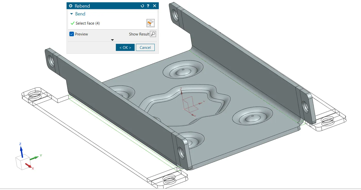
14. Rebending
It restores an unbend feature to its previous bend state along with any features added after the unbend feature.
15. Flat pattern
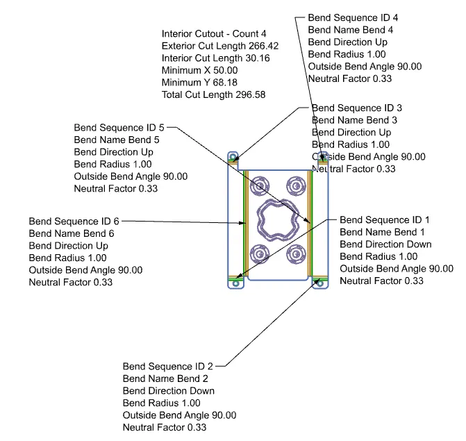
Creates a flat pattern from the formed sheet metal part
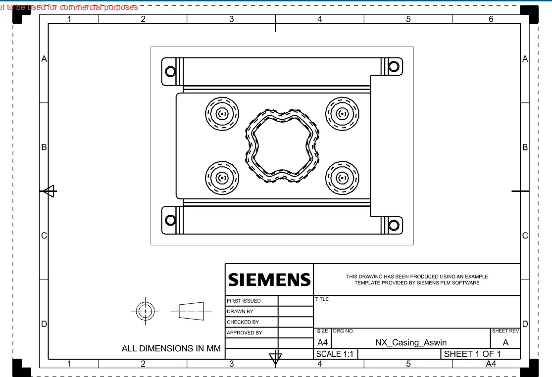
16. Drafting
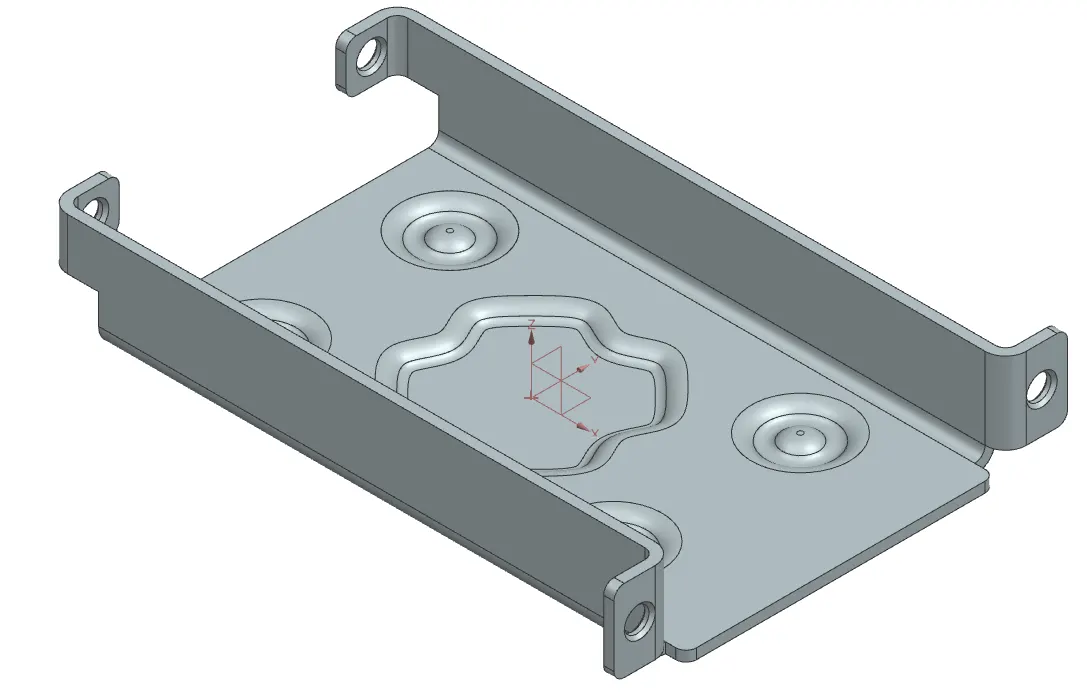
17. Model views
Isometric
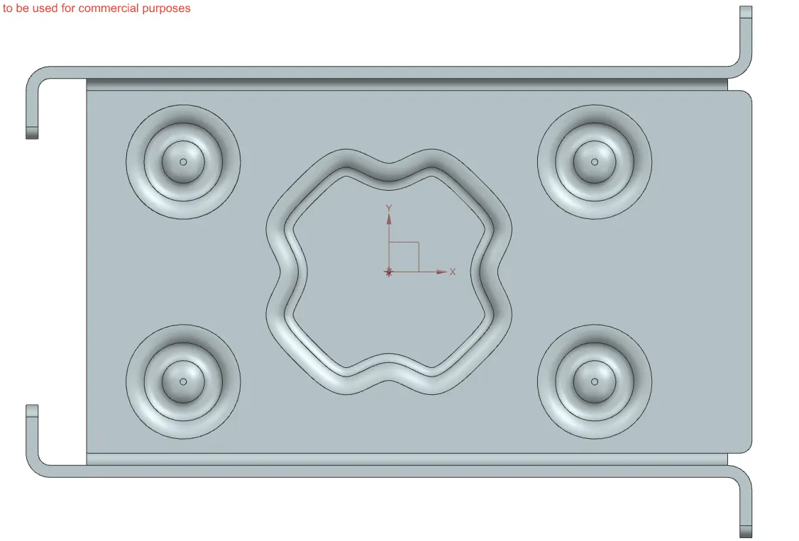
Top view
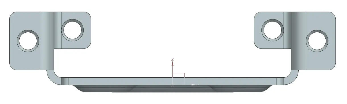
Side view
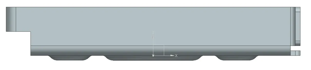
Front view
CONCLUSION
Casing is successfully designed using NX CAD.