Advanced Sheet Metal Design Using NX Cad Challenge_1_Casing Design
Title of the Project
NX Sheet Metal Casing Modeling
Objective
To model sheet metal casing on NX CAD and write detailed report of procedure foolowed.
Introduction
Generally sheet metal components are used as casing or enclosures for different kind of parts. One such casing is to be model in this tutorial.
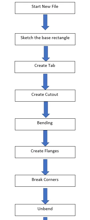
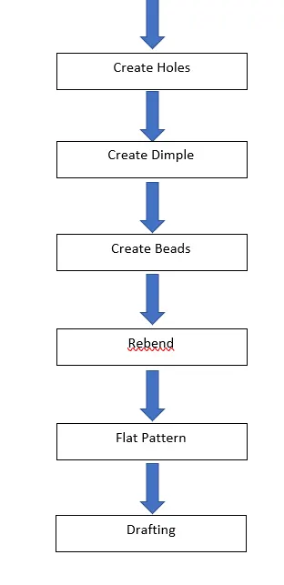
Design methodology / approach (To be explained with the help of Flowcharts only)
Description (Need to explain tools/ Features used while designing)
Create new file naming NX_CASING_OMKAR_GHULE
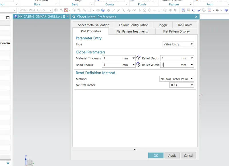
Set all the sheet metal preferences to 1mm.
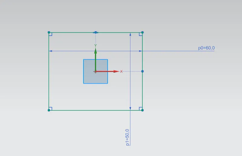
Create rectangular sketch in XY plane. Rectangle of size 60x50mm.
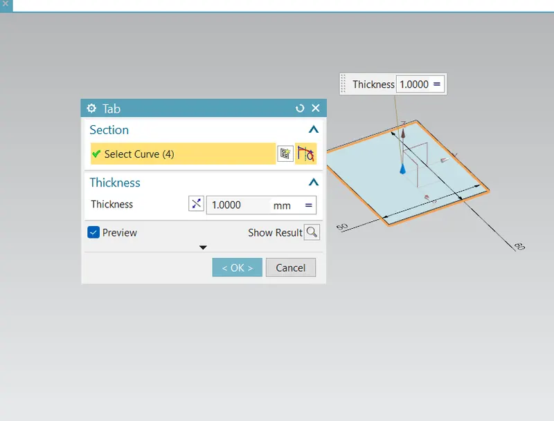
Create tab of 1mm thickness
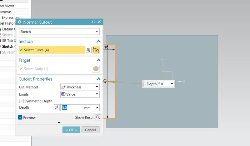
Create 40x5mm cutout at one side of created tab
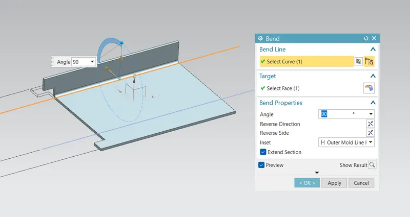
Bend the part from both side by 10mm distance from the edge by 90 degrees.
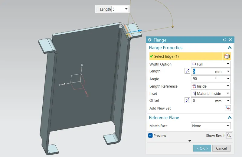
Add flanges on four side of 5mm length as shown in picture.
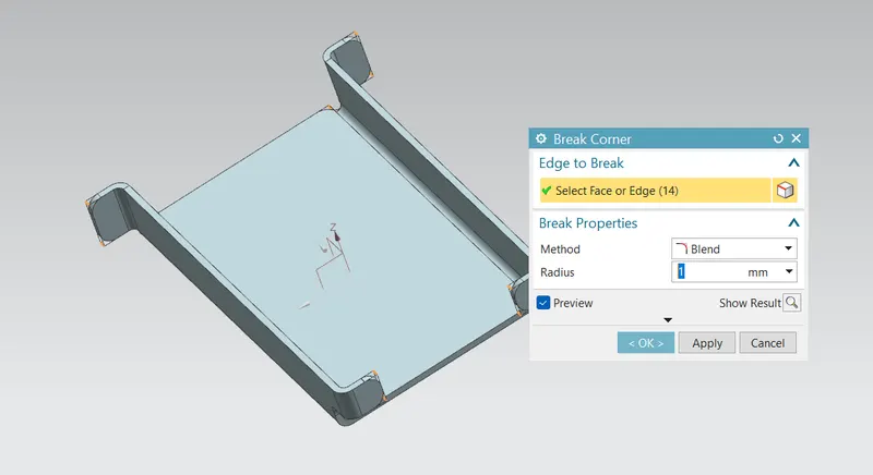
Sharp corners are filleted by using corner break of 1mm.
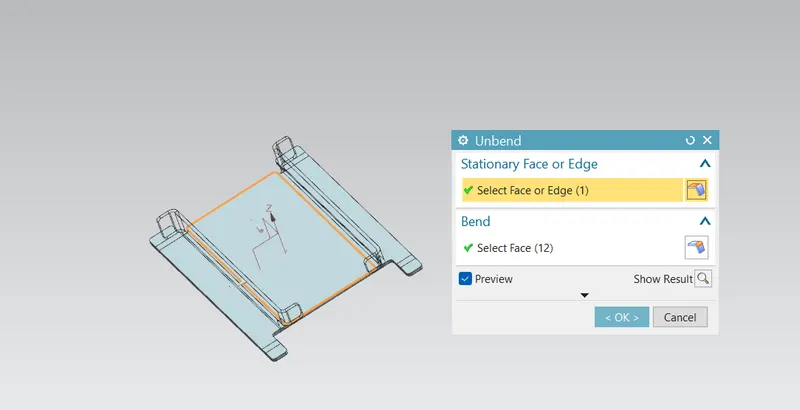
Unbend the part
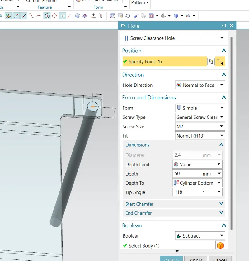
Create screw clearance holes at four corners of part. Holes must be of M2 size.
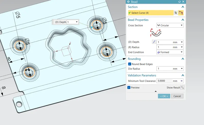
Create dimple by using sketch with 1mm depth.
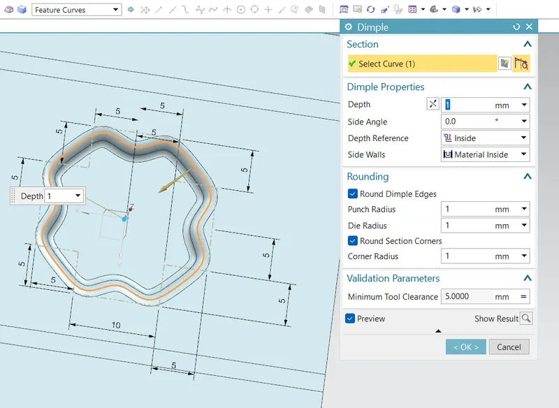
Design beads on four side of 5mm diameter and 1mm depth.
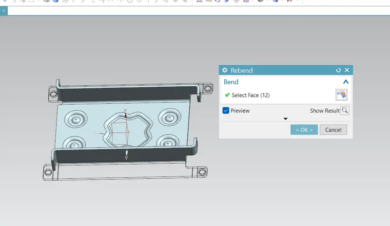
Rebend the part
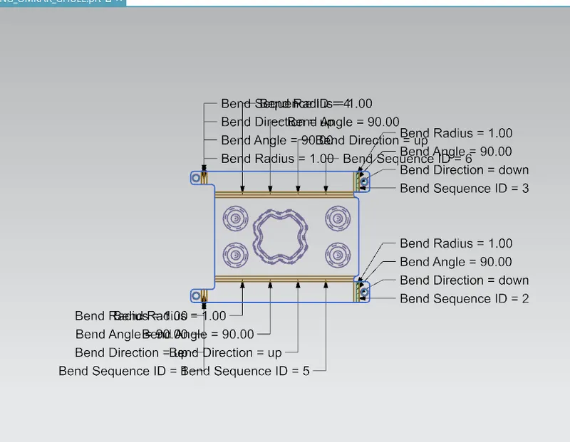
Flat pattern is created
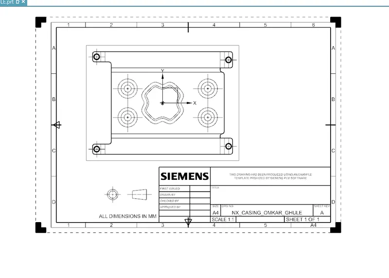
Drafting
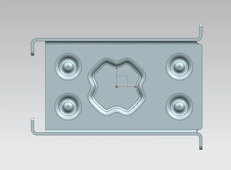
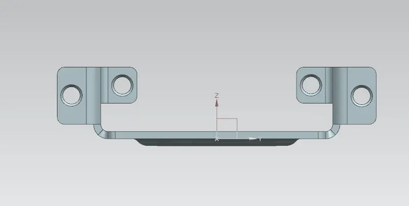
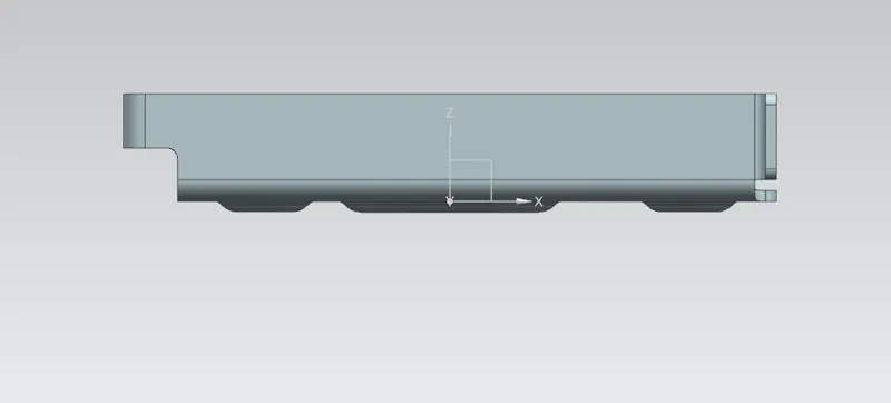
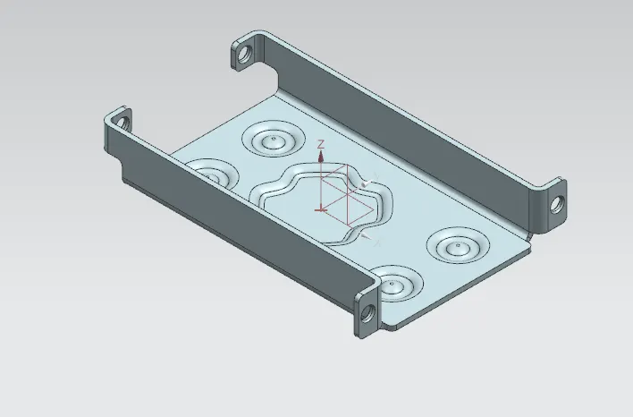
Upload a min of four screenshots of Model in the report. (Front View, Side View, Isometric View and the Top View)
Top:-
Side:-
Front:-
Iso:-
Conclusion:-
In this way casing has been designed using NX CAD.
- Upload a min of four screenshots of Model in the report. (Front View, Side View, Isometric View and the Top View)
- Attach Detailed Drawing Sheet Image
- Conclusion