Advanced Sheet Metal Design Using NX Cad Challenge_1_Casing Design
Sheet Metal Casing
Objective:
Design ‘Sheetmetal Casing’ using Siemens NX Sheetmetal Application.
Introduction
The sheet metal application provide an environment for the design of sheet metal parts used in machinery automotive aerospace et cetera enclosures brackets and other parts normally manufactured with a brake press.
Applications
aircraft bodies
automobile bodies
and Utensile used for domestic purpose beverage cans.
Approach
( Flowchart)
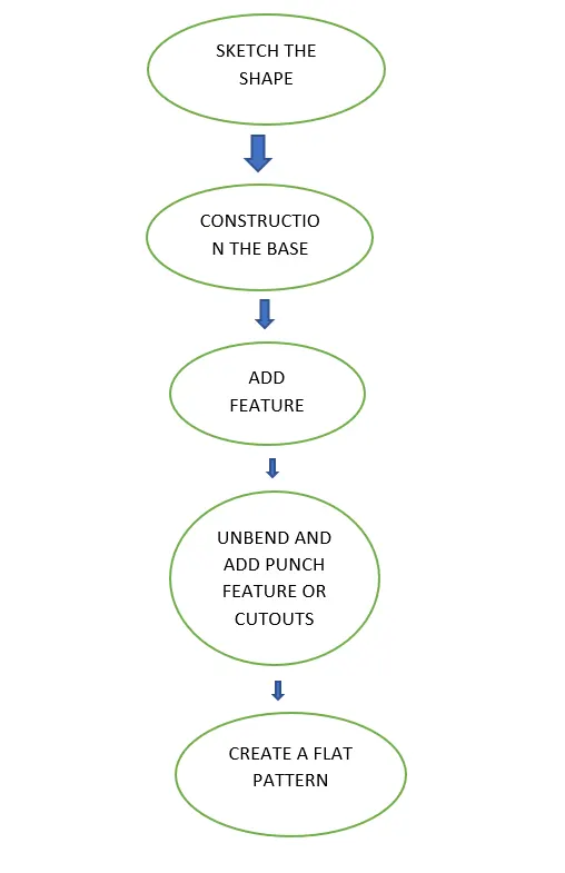
FEATURE USED IN THIS MODEL
Features Used In the Modelling :-
The software used to design this component is NX-CAD also called as Unigraphics. We are exploring the Sheet metal Module of NX CAD in this project. Some of the commonly used features through this modelling are explained as below.
- Sketch - It is the basic of any design.
- Extrude - It creates a feature by extruding a section along a vector.
- Sheet Metal from solid - It builds a sheet metal model that takes its shapes from a collection of planar faces. This command is used to convert the solid body into a sheet metal body. After selecting the command and the solid body, we can also remove the edge sharpness by removing the material at these places.
- Tab - Tab is a command used to create a base for any sheet metal part that can be extruded from a sketch. The sketching plane can be selected as per the designer’s choice.
- Flange - It is used to create an extended part (bend) of a sheet metal. It is created at the edge of one side of the model. This command will allow us to select the edge of the base to create a projecting flat extruded surface. The angle, width, length, and type of flange can be determined as per the requirements.
- Jog - It modifies the model by lifting material on one side of a sketch line, adding a flange between the two sides. Jog is created at another end of the model opposite to the flange. Jog is a command to lift off one whole side of the part. By selecting a line and the plane, the material can be pushed down or lifted off depending on the situation.
- Unbend - This feature is used to unbend the adjacent bends and flatten them. Here it is used to create more features. This command is used to unbend the sheet metal parts to create geometries and work on complicated designs. In this command, we have to select a stationary face and then select the corners of flanges to unbend.
- Rebend - It is used to rebend the corners that were bent before along with any features added after the unbend feature.
- Bead - It lifts material along the contour of a sketch that simulates a stamping tool, it is used for giving strength to the sheet metal. Here two beads are created on the unbent surface. The selected sketch is lifted off from the base to provide strength to the material. Similar to dimple, the material can be removed in both directions.
- Hole - It adds a hole to one or more solid bodies in a part or an asembly with options for counterbored, countersunk and threaded. Here six simple holes are created on the unbent surface with a diameter of 10mm. It can be used to make customized or standardized holes along with a defined point or path. The dept of the hole can be controlled.
- Flat pattern - It creates a flat pattern feature from the formed sheet metal part. The user chooses this command to create a flat view of the sheet metal after unbending all the sides and faces. This view can be used in drawing the flat pattern along with the bend radius and other dimensions.
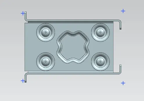
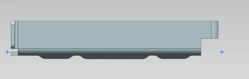
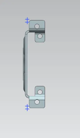
Model in the report. (Front View, Side View, Isometric View and the Top View)
Top view
Side view
Front View
Isometric View

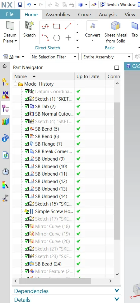
CONSTRUCTION TREE
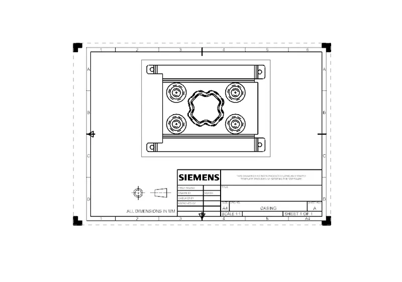
Attach Detailed Drawing Sheet Image
Conclusion