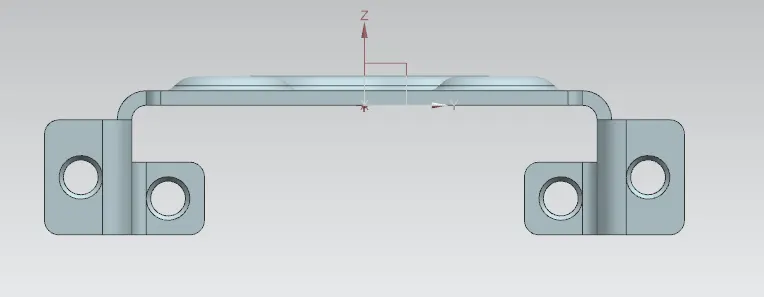
Advanced Sheet Metal Design Using NX Cad Challenge_1_Casing Design
TITLE:
Design of sheet metal casing using NX-CAD
OBJECTIVE:
To design the sheet metal casing using NX-CAD and also draft the flattened sheet metal design.
INTRODUCTION:
A sheet metal casing or sheet metal enclosure is outer body a component where it is presented for its support and asethetical value. An enclosure is made of a sheet metal with bends, cuts, holes and dimples to make a proper shape, grip and positioning a part for a component. Sheet metal is a flat or thin shaped metal which is leaned to a sheet and it has a thickness of 0.5-6 mm.
Flowchart:
- Base and cutout
- Bend
- Flanges and holes
- Unbend
- Embose
- Rebend
- Drafting
PROCEDURE:
1. Create base and cutout
- First of all open the NX-CAD file and create new sheet metal file with proper naming.
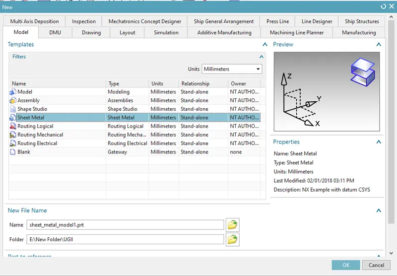
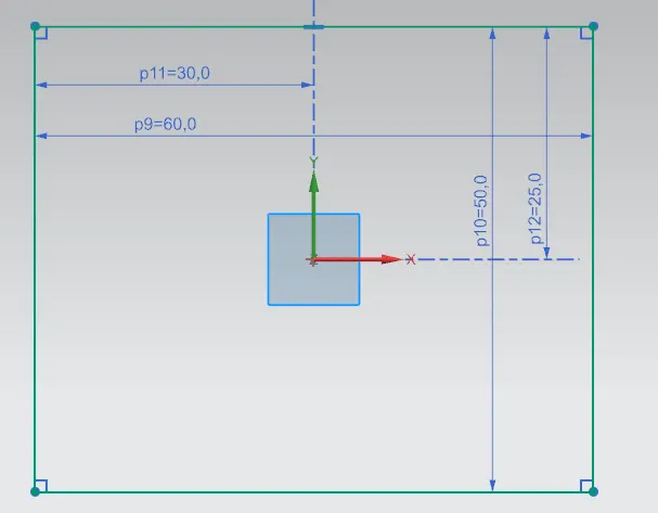
- Next open the sketch option from direct sketch tab and select the XY plane, specify the horizontal vector as X vector and specify the part origin.
- Draw a rectangle with dimensions 60 mm in length and 50 mm in width on XY plane at origin (0,0,0).
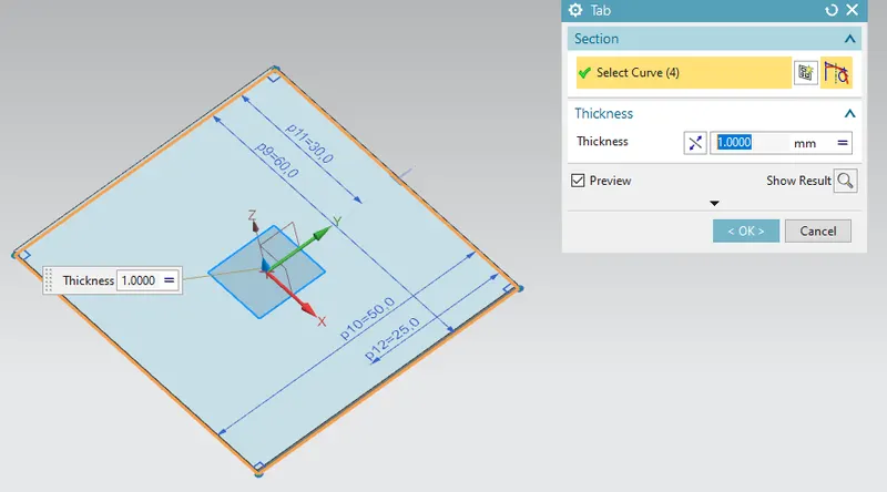
- Modulate the skecth into sheet by selecting the tab option from basic tab and choose the lines, enter the thickness value as 1 mm.
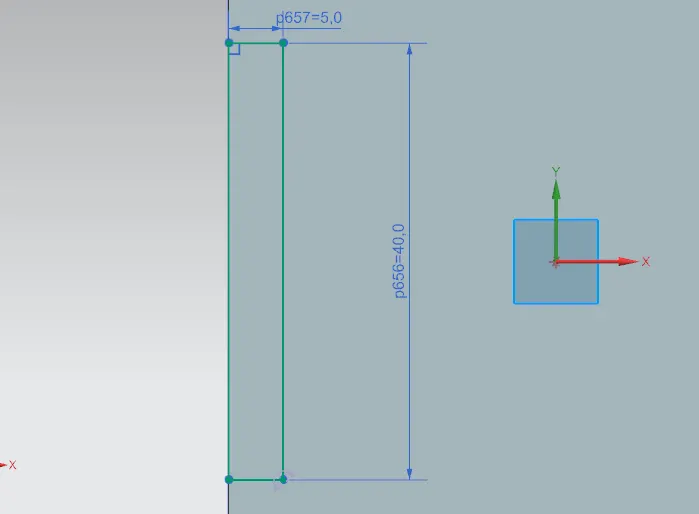
- Create a rectangular sketch form directb sketch tab for 40 mm in length and 5 mm in width on left side of the sheet.
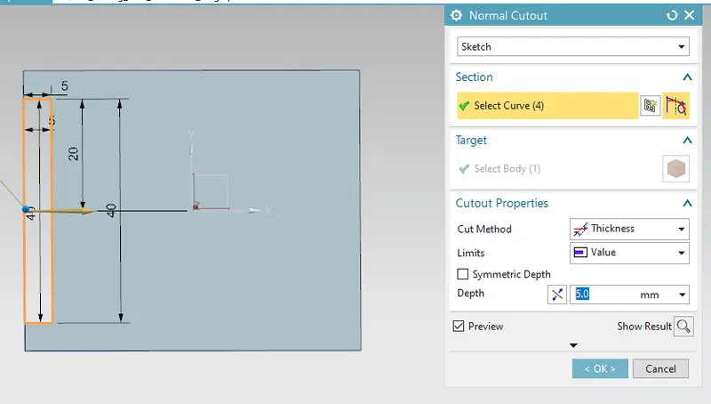
- Modulate the rectangular sketch by choosing the normal cutout command on feature tab and enter the value as 5 mm depth and cut method as thickness.
2. Create bend
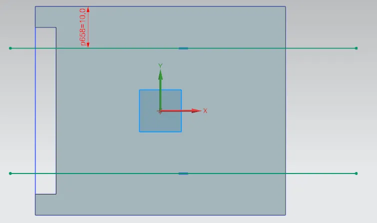
- Draw a two lines for the reference of bends, extended from both ends at 10 mm from either sides in X axis.
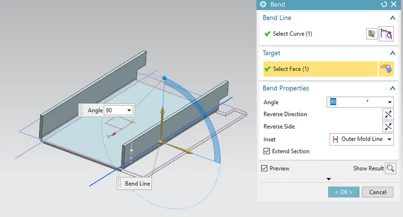
- Select Bend tab>more>bend option and select the reference lines and target as base face. Give angle as 90 degree along inset as outer mold line. (Note: For instance if the bends faces along downwards use reverse side)
3. Create flanges and holes
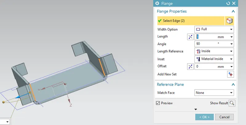
- Create flange from bend tab, select the edges and enter the input values as length 5 mm, angle 90 mm, inset as material inside.
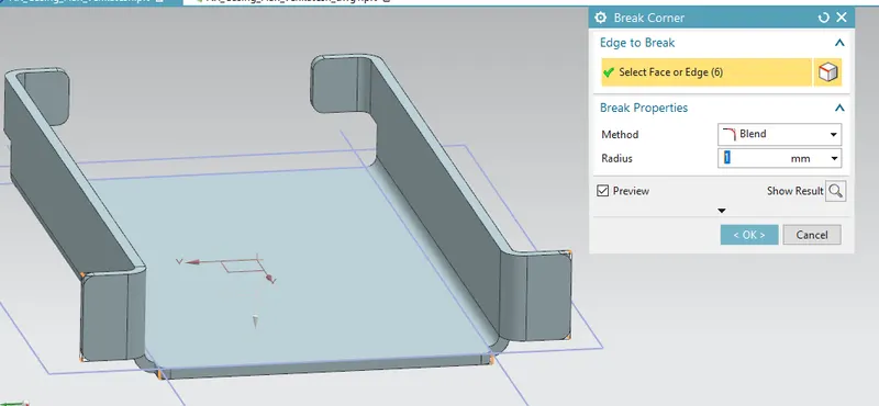
- The flanges has sharp edges use break corner from corner tab and radius value as 1 mm.
4. Unbend the 3D sheet to flat sheet
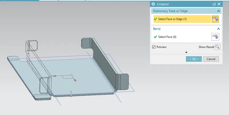
- Unbend the 3D sheet metal design to flattened sheet metal, by using unbend command from form tab and select the edges and adjacent faces.
- Use sketch from direct skectch tab and with the help of flange ends draw a lines with point in its midpoint.
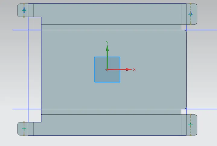
- Use the reference points to create holes by using inputs like hole type as screw clearance hole, screw size as M2, Fit as H13 and depth limit as through body.
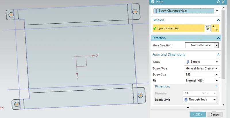
5. Create embose
- Create dimple as cross symbol in center of design using sketch command from direct sketch tab with sides 5 mm.
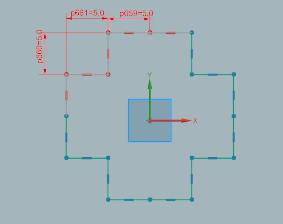
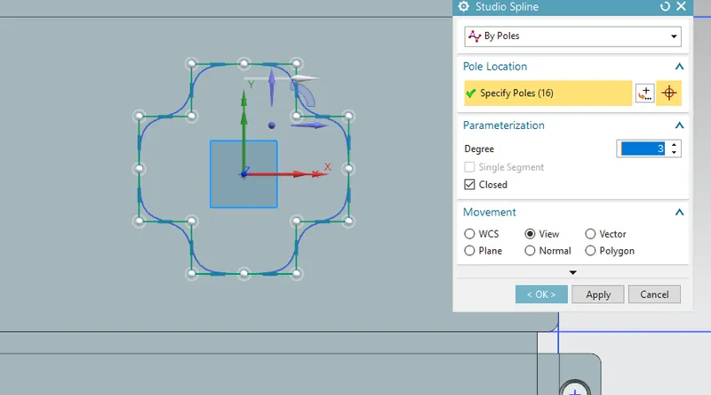
- Use studio spline option from direct sketch tab, create spline ends by selecting 16 points as shown in sketch.
- Input values like Spline type by poles, tick the closed option.
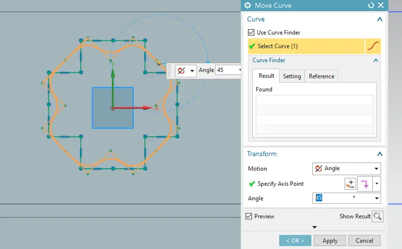
- Next the cross sketch should be tilted 45 degree over its origin (0,0,0) by using move curve command in direct curve tab.
- Use dimple to option create embosement in sheet for 1 mm in depth, Depth reference as inside, side walls as material inside and also select the black triangle to expand the options where rounding section set all three radius as 1 mm.

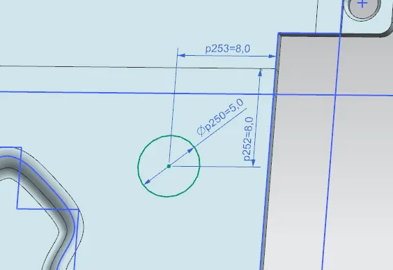
- Create circular embose surrounding the cross in sides by using direct sketch tab>sketch>circle with dimensions as 5 mm diameter, 8 mm away from outer side and outer bend end.
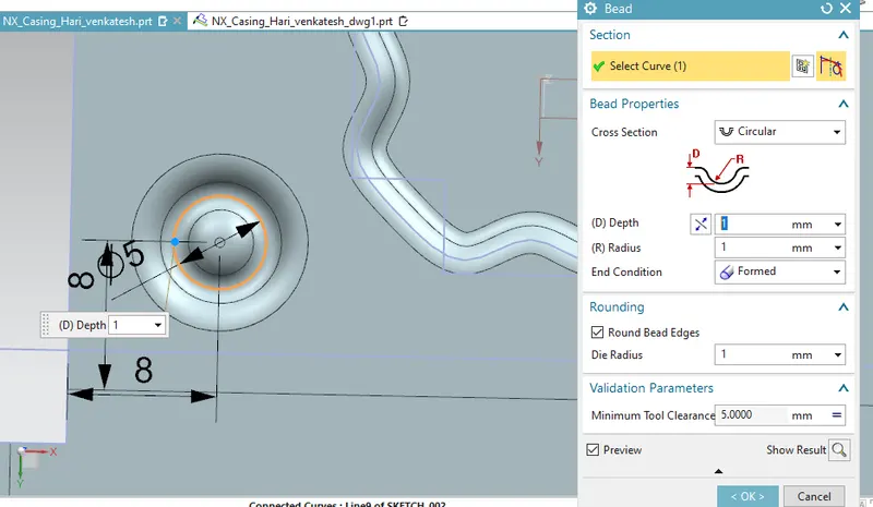
- Use bead option from punch tab, to create a circular embose for 1 mm in depth, 1 mm in radius, end condition as formed and also select the black triangle to expand the options where rounding section set die radius as 1 mm.
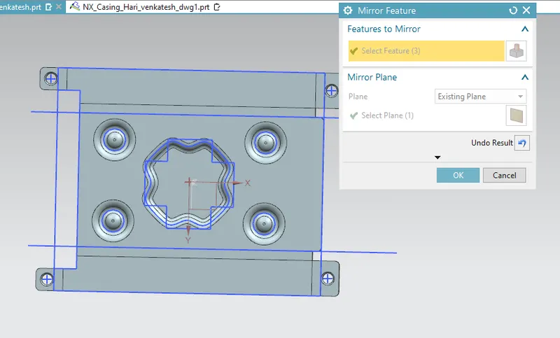
- Mirror the circular embose by X vector as reference using Feature tab>more>mirror feature and also use both the circular emboses to mirror it along Y vector.
6. Rebend the flat sheet to 3D sheet
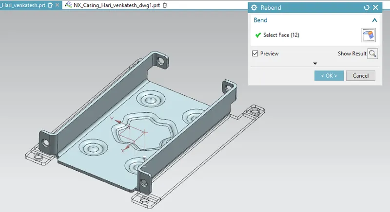
- Use rebend command to return the flattened sheet to 3D sheet design from rebend command in form tab by selecting the bend and flanges orderwise.
7. Draft the flattened sheet
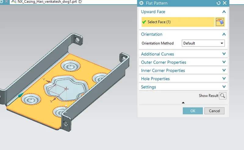
- For drafting, select flat pattern command and click the base face.
- Flattened sheet is not visible, to view it untick the rebend part from part navigator and save the file.
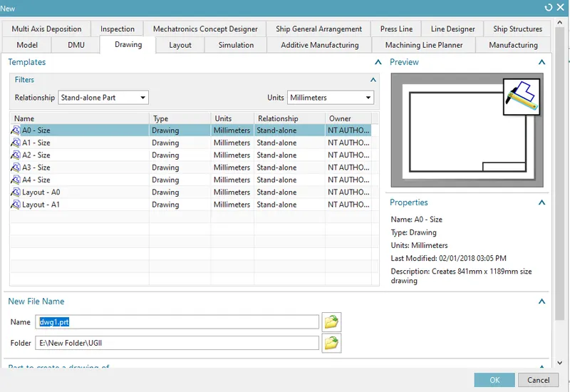
- The flattened sheet should be of an A4 size sheet so open the new file> drawing> A4-size> select ok.
- Use base view from view tab and place the flattened sheet in draft and save the file.

RESULT:
- Draft of sheet metal casing
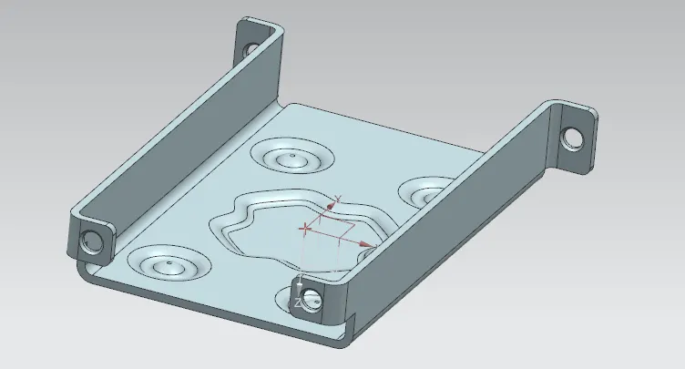
- Isometric view
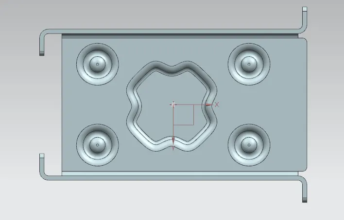
- Top view
- Front view
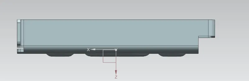
- Sideview