Advanced Sheet Metal Design Using NX Cad Challenge_1_Casing Design
Advanced Sheet Metal Design Using NX Cad Challenge_1_Casing Design
Title of the Project:- To design the Casing Design and Perform Operation tool on sheet metel using in NX CAD Software.
Objective:-
- The main objective what is the Sheet Metal Basics in this project.
- To study the fundamental and advance tools of NX CAD.
- To learn about how operation perfrom on sheet metal
- To study about various parameters and sheet metal designing.
Introduction :-
In this project, the term ' Sheet Metal ' refers to any metal that can be formed into flat pieces of varying thicknees. The used in the sheet metal industry include mild steel, stainless steel, tin, nickel, titanium, aluminum, brass and copper. The design of a casing program involves the selection of setting depths, casing sizes and grades of steel that will allow for the safe drilling and completion of a well to the desired producing configuration.In this , we have to design a Casing Design in NX CAD Software. Firstly we have select the plane and Create on 2 D sketches then those sketches are converted into sheet metal with the help of using various tool and created sheet metal give thicknees value 1 mm.
Design Methodology and Description:-
Flow Chart:-
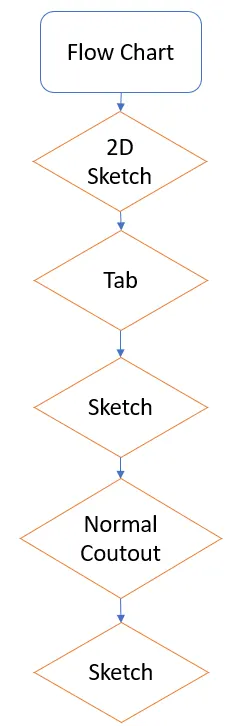
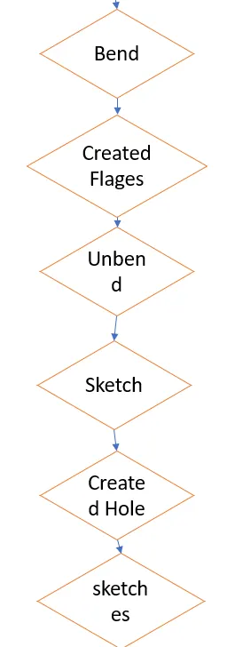
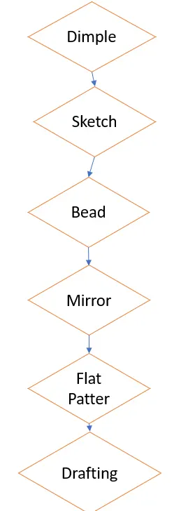
Design Methodology:-
- First We have start the NX 12 Software and create a sheet metal part. Create a sketches in the XY plane and draw the rectangular cetered at original give the Dimensions X-length of 60 mm and a y-length of 50 mm.then the sketches is extruded using the tab feature.
- Tab Tool:- This feature is used to create a extrude a sketches to a given thickness . It is also used for to add the material on the existing tab.
- Create a new sketch in the plane p the upper face of the rectangular sheet. Draw the rectangular symmetric w.r.t the x-axis which is coincident with the left edge of the rectangular is 5 mm wide and 40 mm long.
- After next step go to making normal cutout a rectangure hole in the sheet metal
- Normal Cutout:- The Normal cutout is used for the remove the material from the given sheet and with respect to sketch.
- After tha we have draw the two symmetric line w.r.t the x-Axis. The upper horizontal line is located at 10 mm from the upper left corner of sheet metal and next using the bend feature.
- Bending:- The bending feature is used to the bend the sheet from the given line in the sheet at a 90 angle.
- Next, we have using flanges. The click on flange tool used length of 5 mm and apply the flange.
- Flanges:- Flange feature is used to create a bend at a angle and upto the a given lenght.
- After we have go to Breaking corner feature.Then the bend is created at the corners with the help of cornor breakout.
- Cornor Breakout:- The Cornor Breakout feature is used to break the sharp edges of the cornor with the help of various shapes. In this model we have used circular bend of the give radius.
- Then the click on Unbend tool. Selected as Stationary face and large horizontal face of the metel sheet next select the as bend face on of its.
- Unbend :- The unbend tool is used to unbend the bended tool of sheet metal.
- After we have need to create hole on sheet metal. First create the line which is located in middle of the segments and draw the point center on this line. Then we have click on Hole button and use screw clearance hole as type with a M2 Screw size and a H13 Fit. Create four holes centered on the four point.
- Hole Command:- In the siemens nx modeling, hole command use to create a hole on one or more solid bodies in a part or assembly with option for counterbored, countersunk, and threaded.With hole command, you can make:General holes, Drill holes, Screw holes, Threaded holes, Holes on non-planar faces.
- Next, we have adding the Dimple command on sheet metal. Select the XY plane and create the sketche and click on the studio spline button and select the one by one all the 16 point of the sktches in the clockwise direction.
- Dimple :- The Dimple command makes an indentation in the sheet metal part, using a sketched section as its outline. The difference between the two is that a Dimple feature has a bottom face whereas a Drawn Cutout feature does not.
- Flat Pattern:- Creating a flat solid allows the designer to quickly get a flattened model of the bent sheet metal part. This tool can be extremely useful to measure the total area of the sheet metal required for the component.
- Drafting:- Quickly and easily create engineering drawings from 3D models using highly efficient drafting tools. The drafting software automatically creates drawing views from 3D part and assembly models, and helps you align and scale drawing views and arrange drawing sheets.
Model View (Front View, Side View, Isometric View and the Top View):-
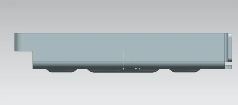
Front View:-
Left Side View:-
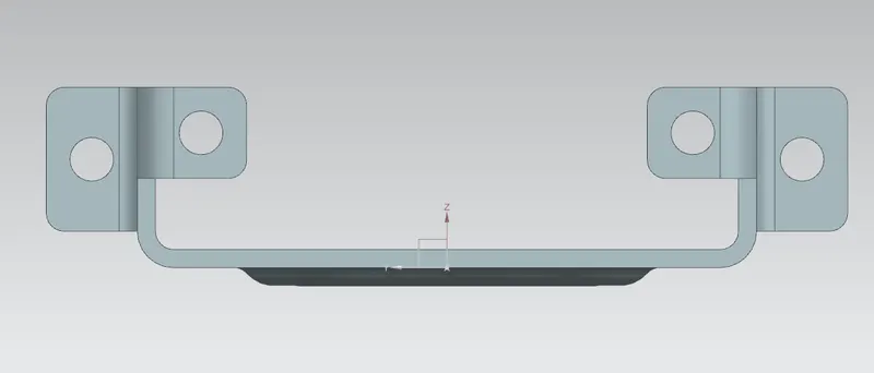
Right Side View:-
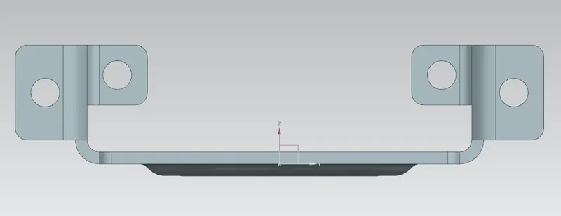
Top View:-
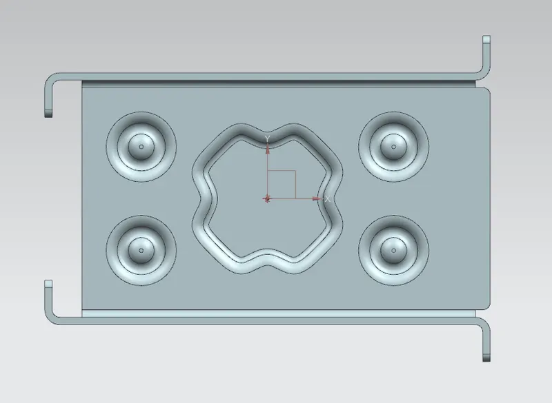
Bottom View:-
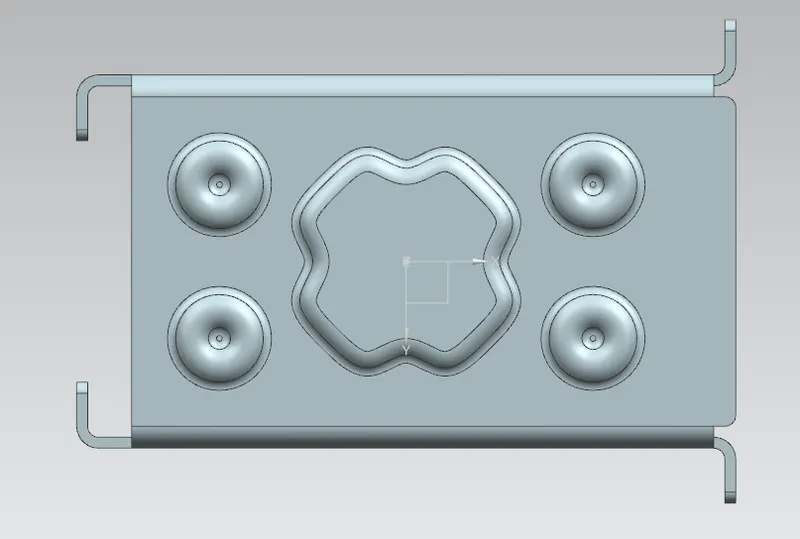
Isometric View:-
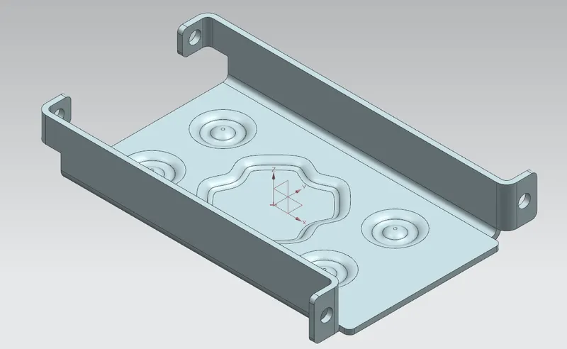
Detailet Drawing Sheet:-
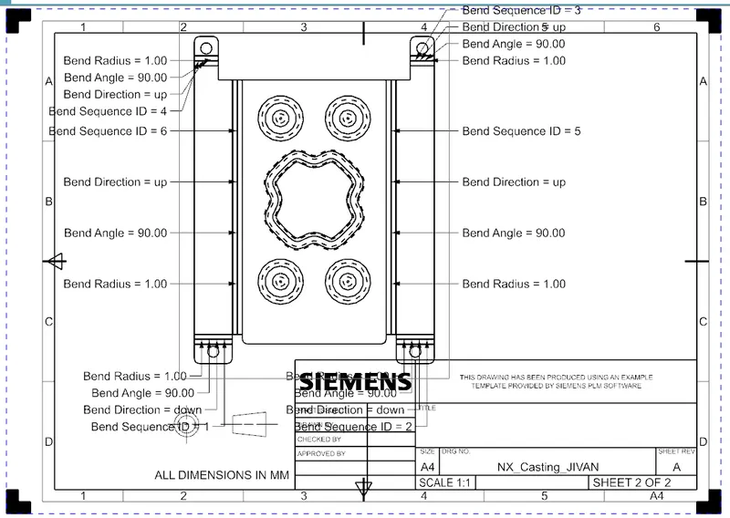
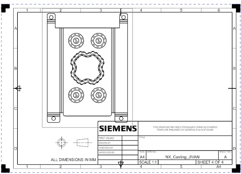
Conclusion:-
In this project I have create Casing Design done. I have learned about the various basics and advanced tool commmand of NX CAD sheet metal. I have used are various command and perform on sheet metal on
created on part like, Tab, Flanges, Hole, Bending and Undending Command, Bend , Adding Dimple , Flat pattern and Making the 3 D part into 2 D skeches.