Advanced Sheet Metal Design Using NX Cad Challenge_1_Casing Design
CASING DESIGN IN NX CAD
OBJECTIVE
The main objective of this project is to design sheet metal casing in the NX application workbench. also to perform drafting for the casing part.
- To design and model the sheet metal casing in NX by using some basic features.
- To learn to create sketches on defined planes as per requirement.
- To master the user interface by basic features like TAB, FLANGE, BREAK CORNER, UNBEND, CREATING HOLES, REBEND, DIMPLE, BEAD, MIRROR FEATURE, AND FLAT PATTERN.
INTRODUCTION
SHEET METAL DESIGN AND FABRICATION
- It is the process of forming parts from the metal sheet by punching, cutting, stamping, and bending.
DESIGN METHODOLOGY
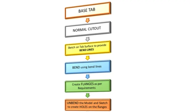
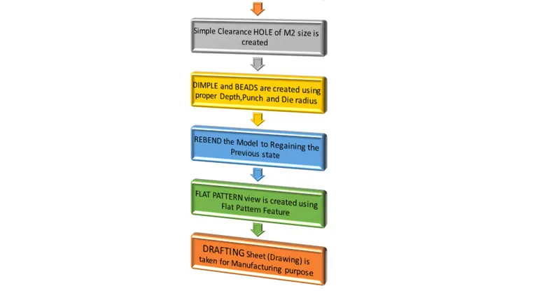
In the flow chart, we are going to discuss step by step.
DESCRIPTION
The sheet metal casing has been done with the above flow chart process. While designing the default thickness, bend radius, relief depth, and relief width value are set to 1mm at the Menu → Preferences → Sheet Metal here you can change the Sheet Metal thickness whenever necessary. The sketch is drawn in the XY plane and the tab command is used for creating the base of the part.
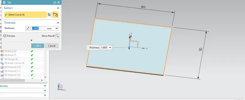
TAB
The tab is the basing feature in the sheet metal environment of NX Cad. The tab is the initial or the start-up stage of the design of the sheet metal component. By using the Tab feature, we create a base for the sheet metal component and decide the thickness of the sheet metal which is then followed in the
further steps of design.
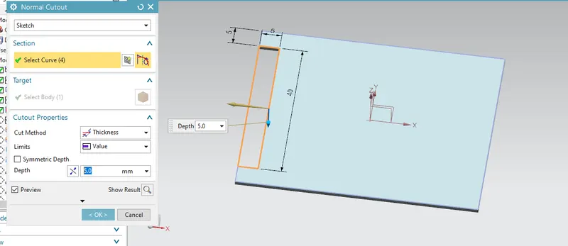
Normal cutout:
This command is used to cut the material by projecting the sketch onto the model and then cutting perpendicular to the faces intersected by the projection.
Bend:
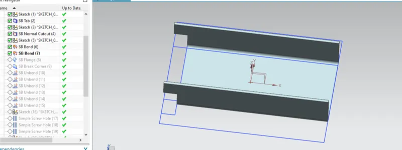
This feature is used to bend the sheet metal as per the required shape. To perform this operation we have to select the face and sketch for bending.
Flange:
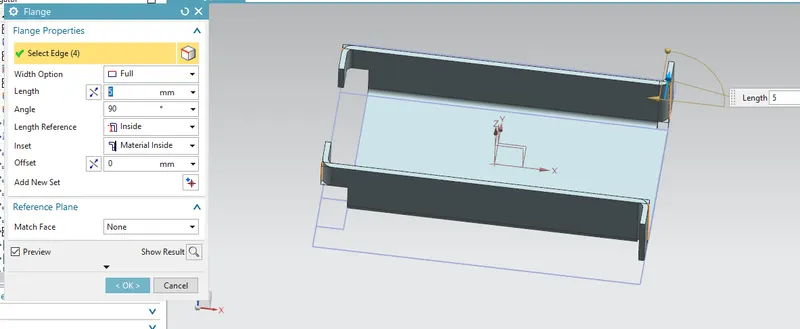
The flange feature is used to create an extended portion or bend to the selected edge. While creating a flange we have to set different parameters such as length of the flange, its angle, length reference (inside, outside, or web), inset (Material inside, Material outside, or bent outside). Other parameters like bend
radius, bend relief, and Neutral factor are also needed to be considered.
Break Corner:
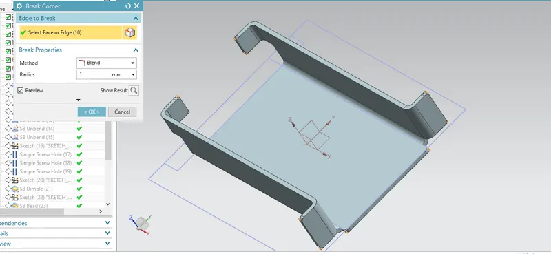
This command is used to round or chamfers the sharp corner of a tab or flange.
Unbend:
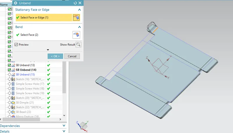
This command is used to unbend the sheet metal. The punching operation can be performed only by unbending the sheet metal.
Hole:
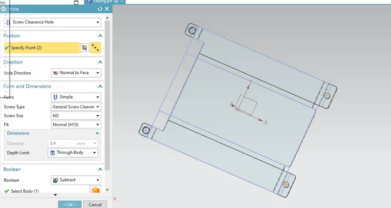
After unbending all the faces and four holes are made by using the hole feature. In the hole feature, we can select the types of holes needed for the requirement.
Dimple:
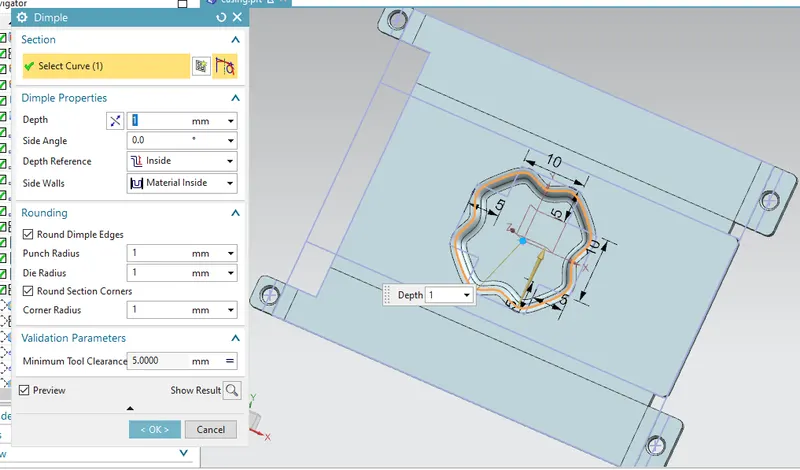
This command is Used to lift an area of the model inside a sketch that simulates a stamping tool. We can create an indentation in a sheet metal part using a sketched section as the dimple outline. The Dimple command makes an indentation in the sheet metal part, using a sketched section as its outline.
Bead:
This feature that we will go over in this post is the Bead. The Bead is like a raised rib in the sheet metal panel. It requires that you have at least one sheet of the metal panel in the active part as well as an open or closed-loop sketch.
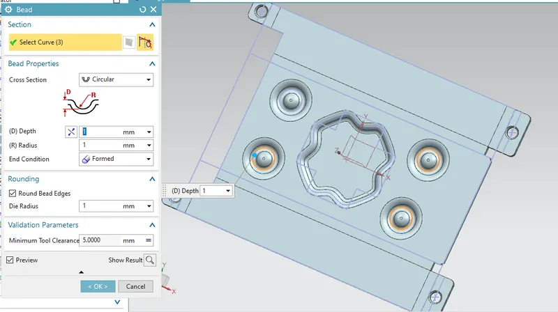
The Bead is another feature that has only a button for Options on the CommandBar.
Mirror Feature:
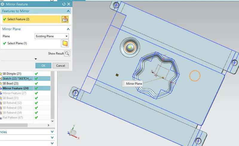
This command is used to mirror the bead feature, now we are going to mirror according to 2 planes (YZ and XZ) plane.
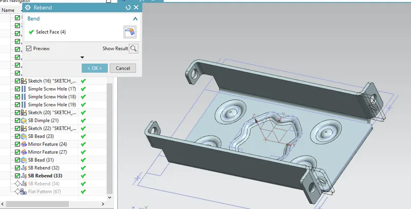
Rebend:
Rebend feature is used to get the original bend shape after performing forming operations like a dimple, bead. After finishing all these operations, then the sheet metal part should rebend to check the DFM (Design for Manufacturing) process.
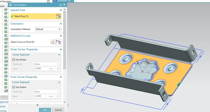
Flat Pattern:
This is used to create an automatically flattened version of sheet metal parts and prepare the model for the manufacturing process. This flat pattern remains the last feature in the model tree.
Drafting
It is possible to create a 2D drawing from a 3D model using the NX Drafting application. With the 3D model opened at NX, go to File > Drafting. ... This will disable the Modelling application and start the Drafting application.
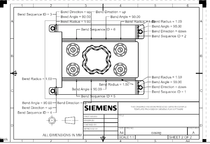
It is also possible to add section views to better detail the model. This can be done through the button Section View.
Required settings:
We want to select the Base view command to show the view of the sheet metal. So, already we have made the Flat Pattern View useful in the Manufacturing process Operations. Change the settings in Model view to Flat Pattern then it will show you the flatter Sheet metal.
Conclusion:-
Sheet metal casing is designed successfully in the NX sheet metal. Basic Features of the sheet metal of NX like creating a Sketch, Tab, Flange, Normal cutout, Break Corner, Bend, Unbend, Rebend, Dimple, Bead, and Flat pattern is learned and applied in Design of Casing.