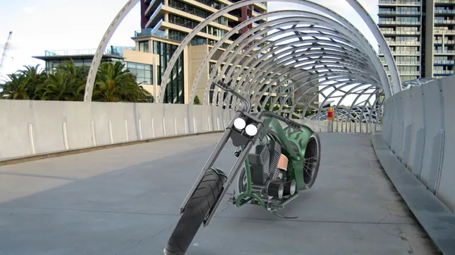
Photo Realistic Rendering
MODELING OF AMERICAN CHOPPER ON SOLIDWORKS
INTRODUCTION
In this project we will look how to model American chopper by using solid works and solid works visualization.
These are the component of the chopper.
- chassis
- Engine with exhaust system.
- Front wheel and Rear wheel with Rims, Sprockets and Calipers.
- Front fork along with handlebars and grips.
- Front and Rear Fenders.
- Oil Tanks.
- Chain and Transmission belt.
- Kick stand and Foot pedals.
After design of these models we will look at the Assembly.
DESIGN APPROACH:
Start with Transmission belt and ending till the rendering section. It has been described step by step.
Let’s discuss what are the features and properties used in the entire model to design different parts:
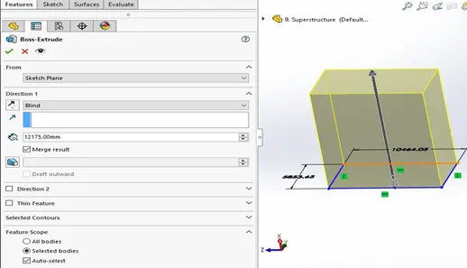
- Extrude boss: Its extrude a sketch to add material. It is most basic command of solid works. As shown in the figure.
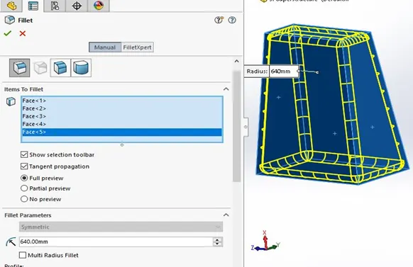
- Fillet: This feature is classified as applied feature and it does not required he sketch It helps to round the Edge/corners. As shown in figure
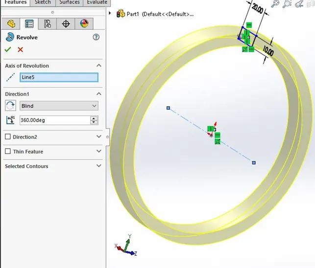
- Revolved Boss Feature: It adds material by revolving a sketch an axis. It is very important to draw an axis the sketch which need to be revolve.
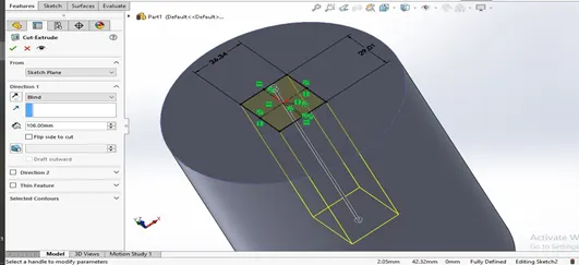
- Extrude Cut: It helps to remove the material from the solid body. It needs the sketch on solid body which need to be cut and will provide desire shape.
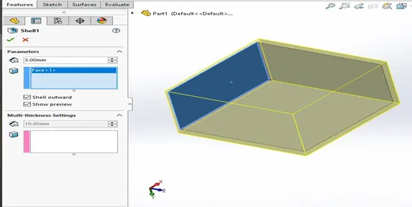
- Shell: I helps to remove material inside the solid body and makes as a hollow model using this feature you can make either completely closed hollow or one face open type model.
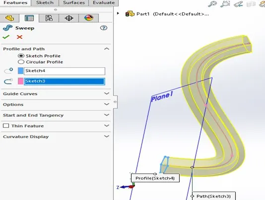
- Sweep boss/Sweep cut: A sweep is a tool that creates a solid, a cut and a surface by moving a profile along a path. To create a solid, use the sweep boss tool to move a profile along a path. The profile contains one or more closed contours.
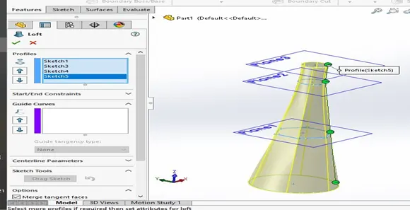
- Loft Boss/ loft cut: It create a shape by making transitions between multiple profiles and guide curves.
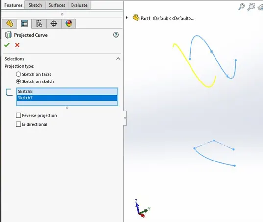
- Projected Curve: you can project a sketched into a model face to create a 3D curve you can also create a 3D curve that represents the intersection of the two extrude surface generated by creating sketches on two intersecting planes.
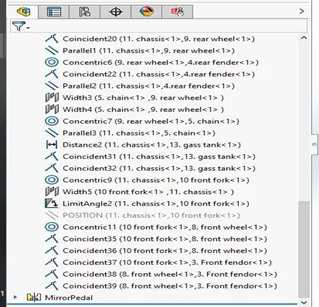
- Mate: Mate creates geometric relationship between assembly component. As you add mates:
- A coincident mate forces two planer faces to become coplanar.
- A concentric mate forces two cylindrical faces to become concentric.
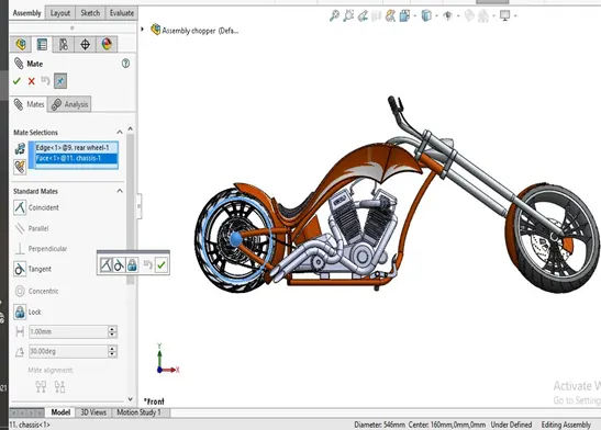
Now we discuss the part of the chopper one by one and last we see the assembly.
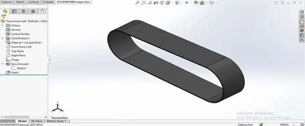
Transmission Belt: In this design we use single extruded surface whose outer edge has been filled and the appearance used on it as a matter rubber. As shown in figure.
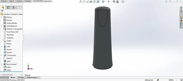
Kickstand: While designing the kickstand we used sketch with additional plane, the sketch we used to create a lofted part and the dome features were applied on both the ends, then we used another sketch to flatten the surface which would rest on the ground to achieve the geometry, we also created an extrude cut for the assembly purposes then we extruded cylindrical boss is created join the cut part and filled is applied to the edge of the cut and joints of the boss. Appearance we used as metal chrome. As shown in figure.
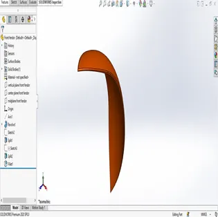
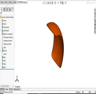
Front and Rear Fender: In these design we used the revolve tool, we revolved the sketch then we used the split tool to remove extra material and also we used the fillet tool to round the outer edge. As shown in figure.
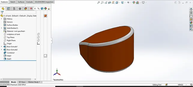
Oil Tank: In this design we used only three tools first we drew the two sketches and extrude that then we used combine feature and applied common command. After these two we fillet the Oil tank at the last we made hollow body with help of shell command.
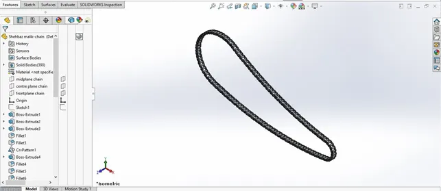
Chain-Link: In this part we have first outline the path of the chain with helps of arcs and lines then created the front and back link which we saved as a block diagram and then simultaneously applied with a concentric relation to one joint of the path then calculatedly we began with the process of curve path arrangement from on joint of the path to another determining the angles and the number of blocks required until the entire loops is complete led finally after sorting out the arrangement we mirror the face of the link to the pins in the block diagram with respect to the mid plane. A fine finished chrome plate metal is used as appearance.
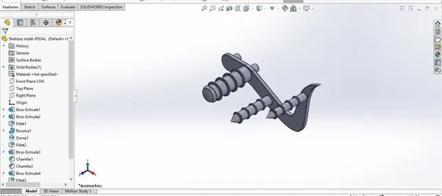
Pedal: In this part first we make the sketch and extrude boss is created with dimension circular holes for the front and the pins which are extruded, now sketch is created on the top plane for the foot rest which is then revolved to make an 3d image the top of the rest is applied with a dome and edges and fillet applied to avoid sharp edge, then chamfer are applied. Then used circular pattern.
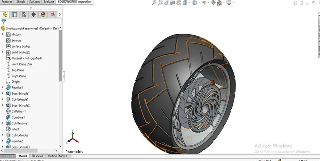
Front and Rear Wheel: The designing of both the wheels are similar the differences are in the size.to begin with the revolved the sketch which is made on front plane. Then we drew the sketch on right plane and extrude both side to make Rim and used extrude cut to cut the rim then we used circular pattern for the rim. Then we sketched circle on the right plane and extrude it to make disk plate and use some command on it. Now we sketched on the right plane to draw a sketch on it and revolved to make the tire part of the wheel and we made some more sketch on the tire to make some grip on it and the pattern all the sketch as shown in the isometric view.

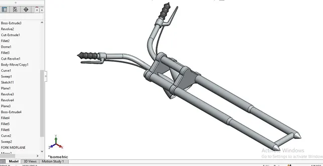
Front Fork: Now we are going to discuss about front fork first we drew the sketch on front plane and revolved it then we used some feature on it like extrude boss, fillet and linear pattern then we designed the front light. And then sketched for the projected curve and made the handle and revolved the sketch for made grip of the handle and used sweep command to made some wire on it then used some fillet on the sharp edge the round it. Then mirrored it then last we used the combine command to combine all the part to make on part. And applied some appearance on it as shown in the isometric view.
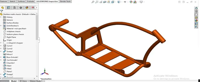
Chassis: the design of the chassis begins with drawing two projected curve to attain the lower curved path of the block which is sweep along the path which is then mirrored to attain the lower geometry a sketch is made and extrude from the open end of the base and a block is created a part from the block is extruded out calculatedly to attain the desired shape and the base of the block is chamfered and the sharp edges are filled both on the exterior and the interior at the end all sharp edge undergoes desired fillet and a plane is added for the purpose of the assembly purposes.
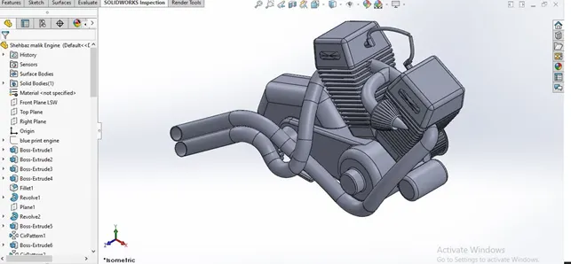
Engine, Motor and the Exhaust System: A sketch is made on the front plane and extruded which is the design of the base of the motor and several bosses are created along with the same sketch to attain a proper shape next the upper curves part is extruded and all the edges are filleted to attain the shape we on the rear side of the motor two revolved feature are made to make the arrangement for the transmission belt and the spokes are made using the extrude and linear pattern around the circular region. The used some command to made other feature of the this par and now comes the designing of the exhaust pipe from the engine to do that projected curve is made both the curves are then joined together to form curve the sweep it at the last appearance given to the engine.
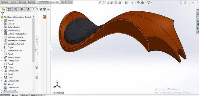
Gas Tank: To start off we must know all the feature used in this come under the surface section of modeling, we begin by making an additional reference plane and drown two sketch on it which is surface sweep to attain the basic layout of the gas, now the edge is surface trimmed to attain the design of the tank one more plane is added and a surface loft is created as affront face and a side face are joined together with the rear part now mirror the entire part and knitting them together now extrude the surface of the seat the use some more command to complete this design and last used some appearance
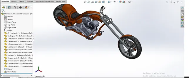
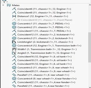
Assembly: after making all the parts the most important part of the assembling the entire chopper to a single file begin. To start by begin by bringing in the chassis first and using its plane and geometry as a base for athe entire solid assembly, the second part we bring in the engine the base stand of the engines are mates so it is fixed. After that we bring the pedal and mate with the chassis then we bring the kickstand mate with chassis with concentric mate applied on it after that we bring the transmission belt and mate with engine. Now we come in the rear wheel the plane of the wheel mated accordingly then raer fender also mated. Now chain link is brought on to start a width mate with respect to chassis. Then front fork mated accordingly with upper part of chassis after the all part mated accordingly and complete the assembly as shown in isometric view.
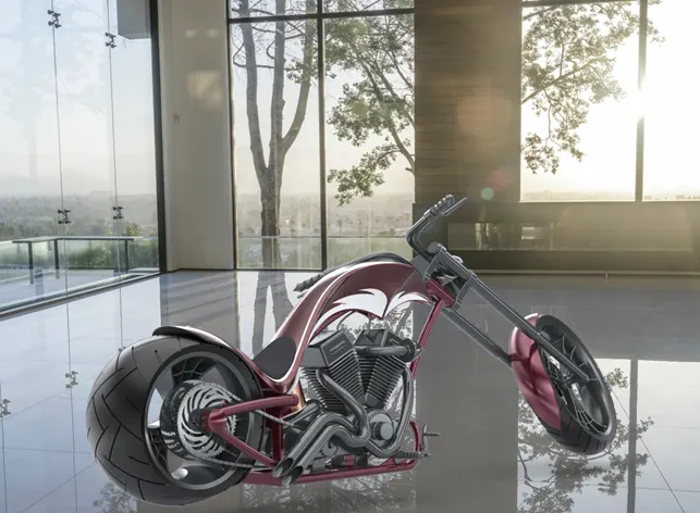
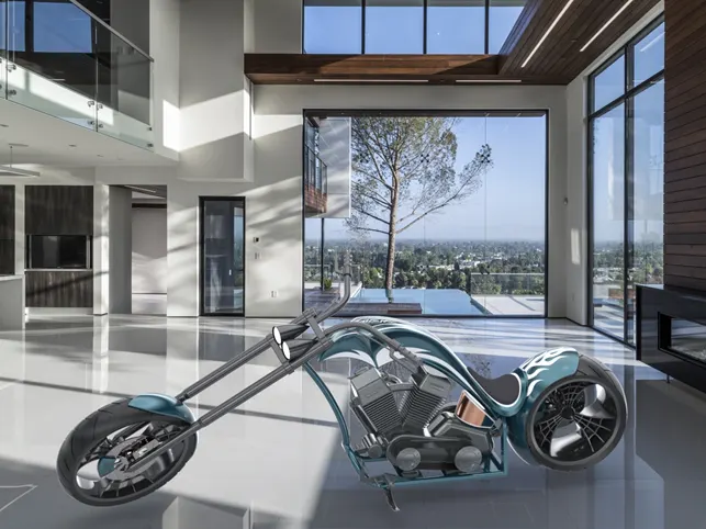
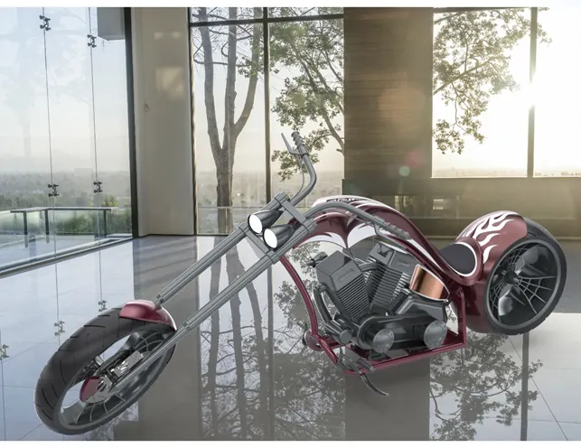
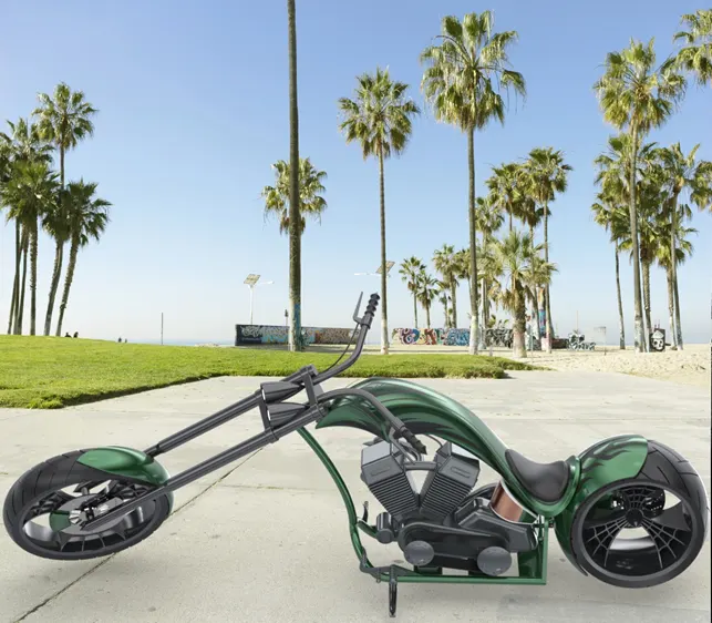
Rendering: The final step of this project to make the project realistic with the help of rendering. Now we discuss the use of rendering. First we add some decals on the rear fender and face of the oil tank now make more realistic to add camera view setting on it. Now we take our assembly file into solid works visualize where we start the rendering then we apply some realistic background and color to this chopper make it realistic as shown in figure.