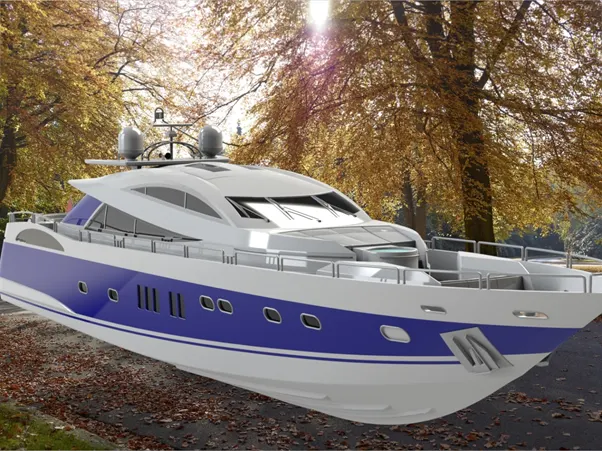
Surface Modeling of the American Predator Yacht
Design, Assembly and Photo-Realistic Rendering of an American Predator Yacht
OBJECTIVE
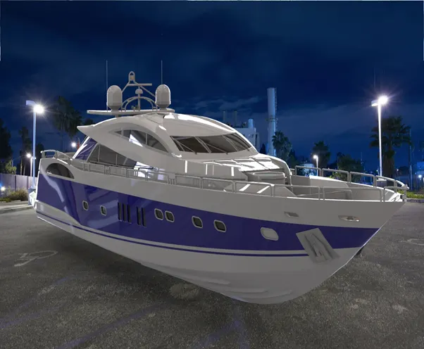
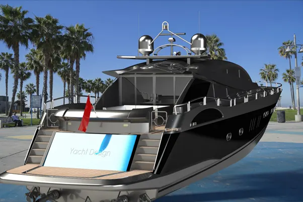
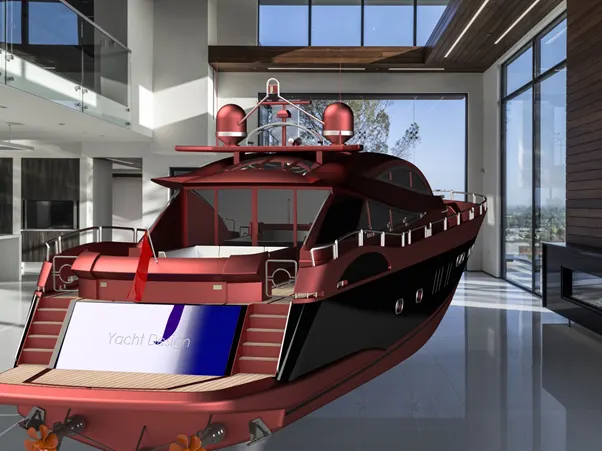
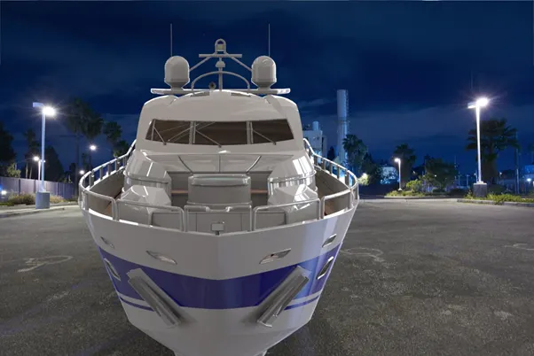
The objective of the project is to design and model all the parts of an American Predator Yacht and assembling in it to create the Photo-Realistic Rendering of an American Predator Yacht.
INTRODUCTION
In this project we will look how to model American yacht by using solid works and solid works visualization.
These are the component of the chopper.
- Propeller
- Radar
- Blue-print
- Hull
- Garage door
- Front-seat
- Middle-seat
- Rear-seat
- Superstructure
- Radar-mast
After design of these models we will look at the Assembly and Rendering.
DESIGN APPROACH:
Start with Propeller and ending till the rendering section. It has been described step by step.
Let’s discuss what are the features and properties used in the entire model to design different parts:
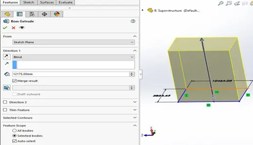
Extrude boss: Its extrude a sketch to add material. It is most basic command of solid works. As shown in the figure.
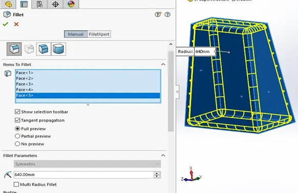
Fillet: This feature is classified as applied feature and it does not required he sketch It helps to round the Edge/corners. As shown in figure
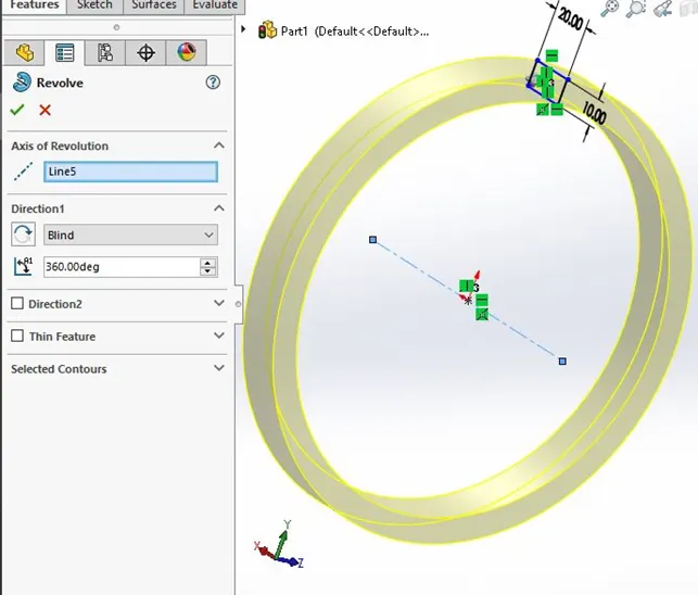
Revolved Boss Feature: It adds material by revolving a sketch an axis. It is very important to draw an axis the sketch which need to be revolve.
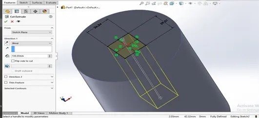
Extrude Cut: It helps to remove the material from the solid body. It needs the sketch on solid body which need to be cut and will provide desire shape.
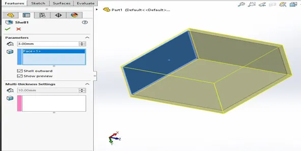
Shell: I helps to remove material inside the solid body and makes as a hollow model using this feature you can make either completely closed hollow or one face open type model.
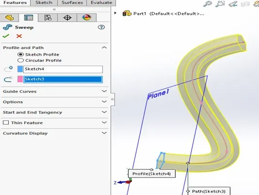
Sweep boss/Sweep cut: A sweep is a tool that creates a solid, a cut and a surface by moving a profile along a path. To create a solid, use the sweep boss tool to move a profile along a path. The profile contains one or more closed contours.
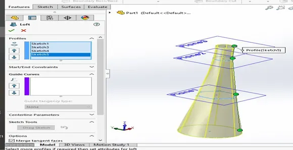
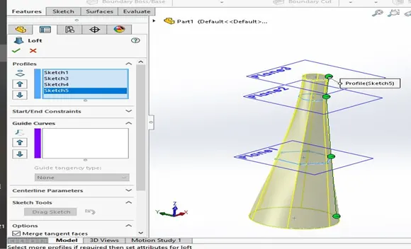
Loft Boss/ loft cut: It create a shape by making transitions between multiple profiles and guide curves.
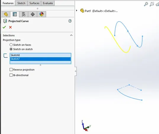
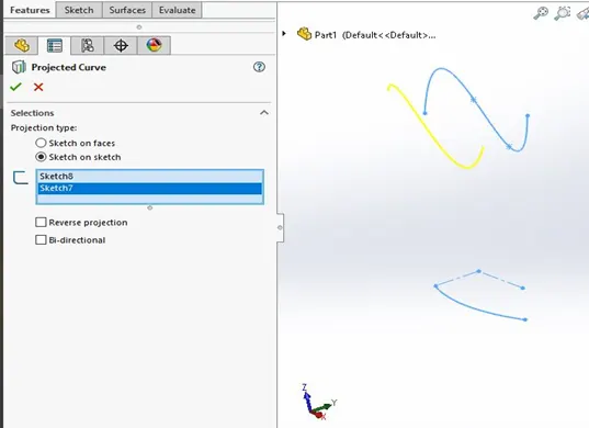
Projected Curve: you can project a sketched into a model face to create a 3D curve you can also create a 3D curve that represents the intersection of the two extrude surface generated by creating sketches on two intersecting planes.
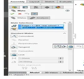
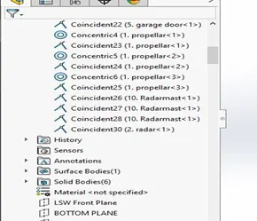
- Mate: Mate creates geometric relationship between assembly component. As you add mates: A coincident mate forces two planer faces to become coplanar.
A concentric mate forces two cylindrical faces to become concentric.
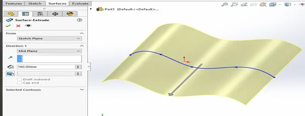
Extrude Surface: It extrude the sketch and make surface it can extrude line into surface its most common command in surface as shown in figure.
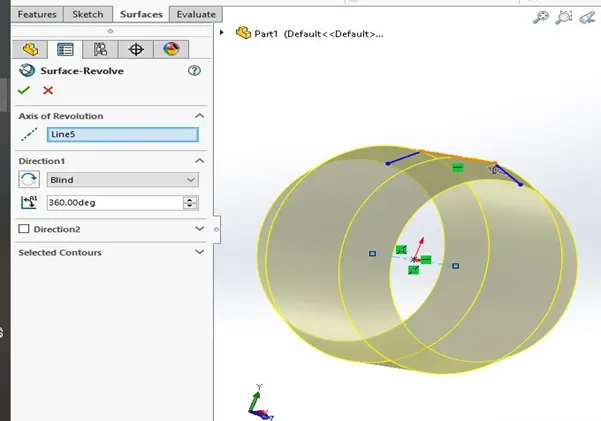
Revolve Surface: This features you can use for revolve the surface in this features we must have axis for revolve the sketch as shown in below.
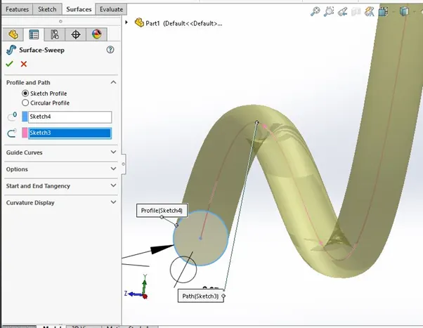
Swept Surface: This feature we can use to extrude with the help of guide sketch as shown in below.
Loft Boss/ loft cut: It create a shape by making transitions between multiple profiles and guide curves.
Projected Curve: you can project a sketched into a model face to create a 3D curve you can also create a 3D curve that represents the intersection of the two extrude surface generated by creating sketches on two intersecting planes.
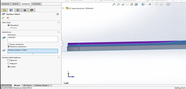
Trim surface: In this feature we can trim the extra surface of the model as shown in figure.
Knit surface: this feature is very useful for combine the two different surface into one surface its also make solid body.
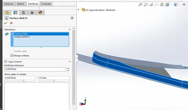
Now we discuss the part of the chopper one by one and last we see the assembly.
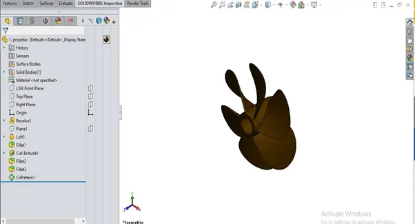
Propeller: In this design we will see how to design propeller first we sketch the circle and revolve it then we take plane to draw some sketch and use loft command to make wing of the propeller and give some fillet.
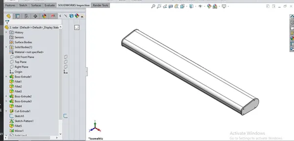
Radar: this design is very handy to make take simple sketch and extrude it and then give some fillet to round the corner as shown in figure.
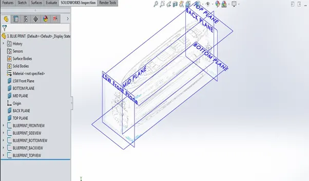
Blue-Print: this is very important for us because we will use it after all the model so we must arrange in proper manner as shown in the figure.
Hull: Now we are going to discuss about hull it is very important part of the yacht in this model we used surface modeling first we drew some curve the we join this curve to make surface with the help of loft surface command when make lots of surface we used lots of command like trim surface , knit surface, ruled surface, extend surface and filled surface as we told about it in the above then we use some appearance and use also photo view 360 to decal the surface of the hull as shown in figure.
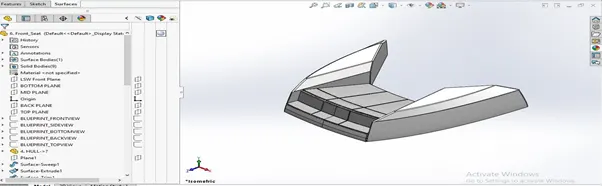
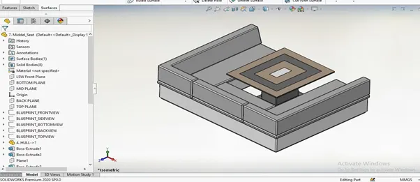
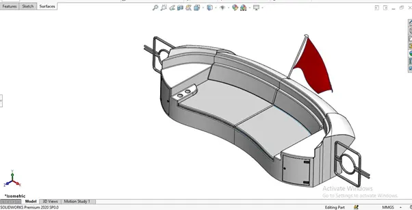
Front, Middle and Rear Seat: First we took the blue print and also we took the hull surface then we sketch and use some command to make our front seat. Then we used fillet command to round it then we knit the surface whose we made and make one surface and also we used revolve command and make half part of the seat then we mirrored and complete the seat then we again applied some fillet. After we used all feature of the surface accordingly then we applied some appearance on it.
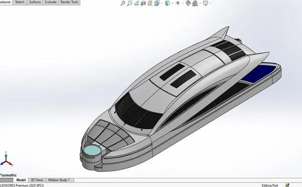
Superstructure: Now we discuss about the super structure it compete surface model we will use lots of surface command. First we tool blueprint with hull surface and the drew some curve with the help of curve projected command the we used surface loft command and made the surface then we repeat again these step to made another surface the we used trim surface to remove extra surface and then we knitted all the surface in one surface then we use dome command for it to look realistic after all the surface we completed then we make super structure in solid body and the mirror it after that we applied some appearance and fillet as shown in the figure.
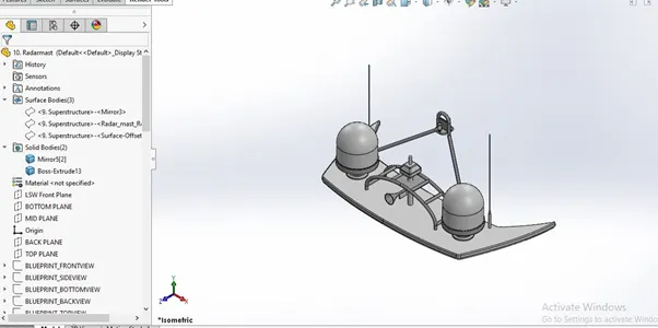
Radar Mast: Now we discuss about the radar mast first we took the blue print with hull surface the we sketch accordingly and use some command to make our model in proper manner as shown in figure.
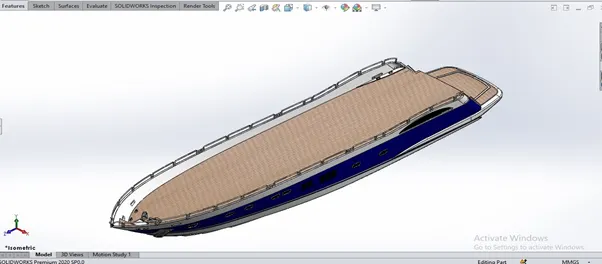
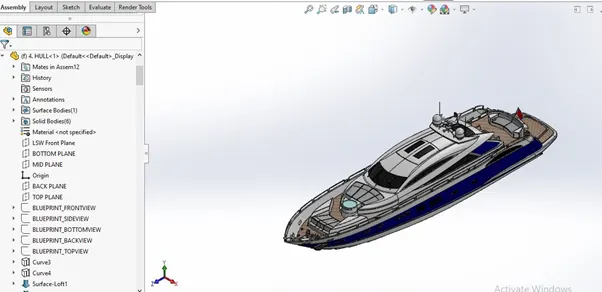
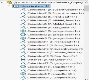
Assembly: after making all the parts the most important part of the assembling the entire Yacht to a single file begins. To start by begin by bringing in the hull first and using its plane and geometry as a base for the entire solid assembly, the second part we bring in the hull the base stand of the superstructure are mates so it is fixed. After that we bring the superstructure and mate with the hull then we bring the seat mate with hull with concentric mate applied on it after that we bring the propeller and mate with hull. Now we come in the garage door the plane of the hull mated accordingly then radar mast also mated. Now radar is brought on to start a width mate with respect to radar mast. Then mated accordingly with upper part of hull after the all part mated accordingly and complete the assembly as shown in isometric view.
Rendering: The final step of this project to make the project realistic with the help of rendering. Now we discuss the use of rendering. First we add some decals on the hull and superstructure now make more realistic to add camera view setting on it. Now we take our assembly file into solid works visualize where we start the rendering then we apply some realistic background and color to this chopper make it realistic as shown in figure.