Hood design-Week 2
DESIGNING A CAR HOOD-BIW INNER PANEL AND OUTER PANEL
OBJECTIVE
The main objective of this project to design the hood of a car that satisfies the manufacturing requirement. The body in white (BIW) inner panel and outer panel must be assemble with the Hinge Assembly, Latch and Striker with thier reinforcements.
INTRODUCTION
A CAR HOOD, also reffered to as a bonnet in some other countries, is the hinged cover that rests over the engine of a front-engine vehicle. its purpose to prvide access to the engine for repair and maintenance. A concealed latch is typically used to hold down the hood. Car hood are typically constructed from steel and sometimes from aluminium. aftermarket car may be constructed from varius material like carbon fiber, fiberglass. or dry carbon.
Body in White is the stage in automobile manufacturing in which car body's frame has been joint togather it is done ferore the painting and before the motor, chassis sub-assemblies, or trim have been interated into the structure.
DESIGNING THE HOOD
Software used: NX CAD
Manufacturing Required:
Minimum fillet radius=3mm+thickness.
No sharp corners inside the component.
No curvature leeser then 5mm.
Small embosses should not exceed the maximum depth of 6mm (staying on the safe side).
Mounting area and welding area need to be flat.
Provide appropriate corner relief on the area od curvature.
Provide exact mastic point to reduce the NVH.
Data to be used:
Hood thickness information
Outer panel thickness=0.75mm
Inner panel thickness=0.75mm
Reinforcement thickness=1.5mm
DESIGN APPROACH
TOP DOWN APPROACH
In this approach we will start to design by defining but not detailing its first-level components. Each component is then refined in more details by defining its sub-components. The process is continouse till all Low-level components are defined and detailed.
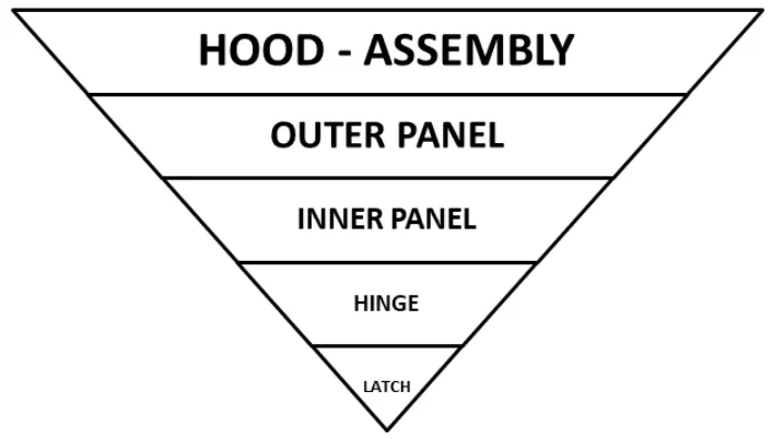
In this project the top down approach was used because the styling and reinforcement wre already designed. Hence by creating the assembly then the hood inner panel is designed and the embosses for positioning the hinge assembly, latch and striker were created.
A SHORT STUDY ABOUT DESIGN
EURO NCAPSAFETY STANDARD
EURO New car assesment programme is a safety assessment center that evaluates the safety performance of the car. They evaluate potential risk of pedestrian impact in the event of collision with the car and providing rating for the new vehicles.
Hood is part that reduce the risk of potensial head injury during pedestrian impact and it is there for vital to validate the Head Impact Zone for better NCAP Assesment Rating.
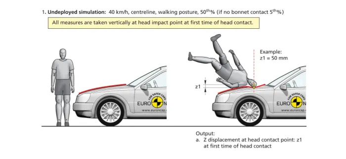
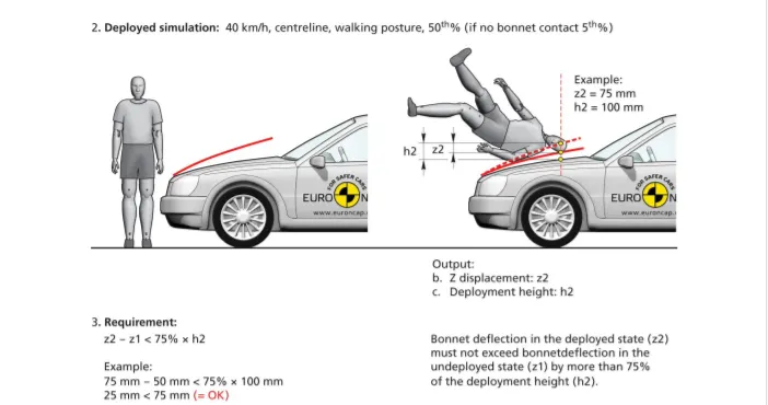
Hood are Two types
- When the side reference line drawn from the ground intersects the CAR Hood is called wrap around the Hood.
- When the side reference line drawn from the ground intersects the CAR Fender is called Inlaid hood.
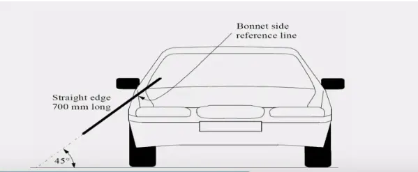
Side reference line
Wrap Around Distance determine the impact of Head, Pelvis and Leg of the pedestrian.

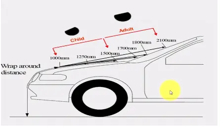
Based on these factor IMPACT ZONE are plotted and CHILD and while packaging of components like Engine, Fuse Box, Control Unit in the Engine compartment an offset distance is provided from the output panel and interference of IMPACT DEFORMATION ZONE should be lower for for better NCAP rating
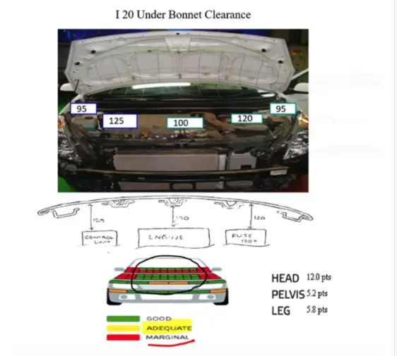
Packing of component with clearence from bonnet
Taking this into criteria Hood is designed to have much greener head injury criteria.
DESIGN REPORT
MASTER SECTION
The master section is the input which is predefined sketch suitable for various design situation and it used to develop the hood model using the hood styling surface.
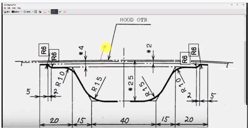
Image I: Master Section Data for Hood Panel Creation
Styling surface are aesthetic surface obtained from the CLASS A Styling Team and is used by the new product design team as a parent model to develop the pessenger hood model.
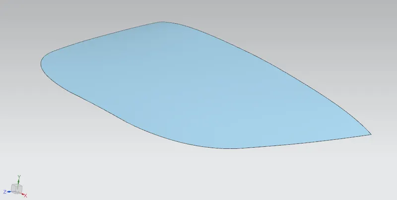
Image II: Styling Surface Hood Panel
Design Requirement
The basic Design requirement for Hood design are
i. Opening Angle Situation
ii. Emboss of inner panel
iii. Heming and relief along the outer panel
iv. Hinge Axis Defination and Latch and Striker Position
v. Stiffener Pad and Mastic Sealant for NVH improvement
vi. Positive Draft Angle for deep drown steel part
PASSENGER CAR HOOD MODEL
- Hood is an Exterior part Trim that cover the Engine compartment and provides styling in the front of the car
- It one of the vital components that requires frontal crash requirements and pedestrian impact safety standards
- After understanding the requirements a top down design approach is followed to pepare the final model
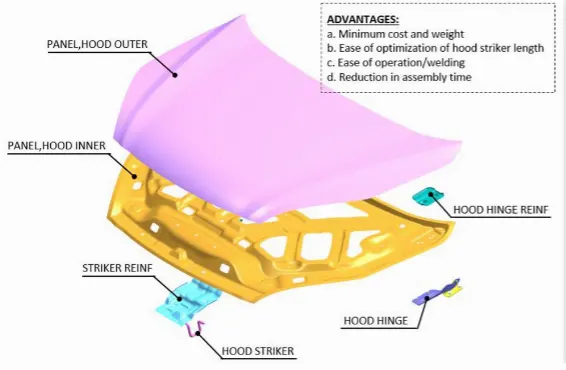
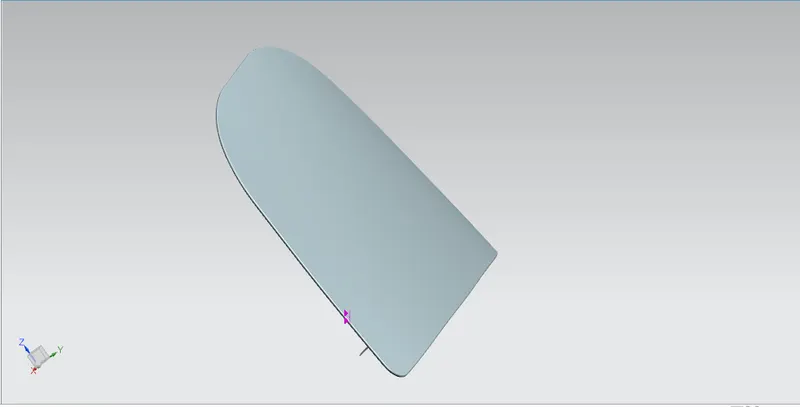
Image 3) Hood Panel
The Operations used to develop the Hood Panel in NX CAD are
- Surface offset
- Offset curve face
- Trim sheet
- Through Curve
- Law Extension
- Trim and Extension
- Trim Body
- Extend Sheet
- Edge and Face Blend
- Emboss
- Bridge Curve
- Mirror Geometry
- Sew
- Thicken
INNER PANEL
The inner panel of the Hood is more vital which involve various engineering aspects and attachment features. The Input styling surface is validate for surface discontinuities and using surface operation in NX the styling surface is developed along the predefined master section data.
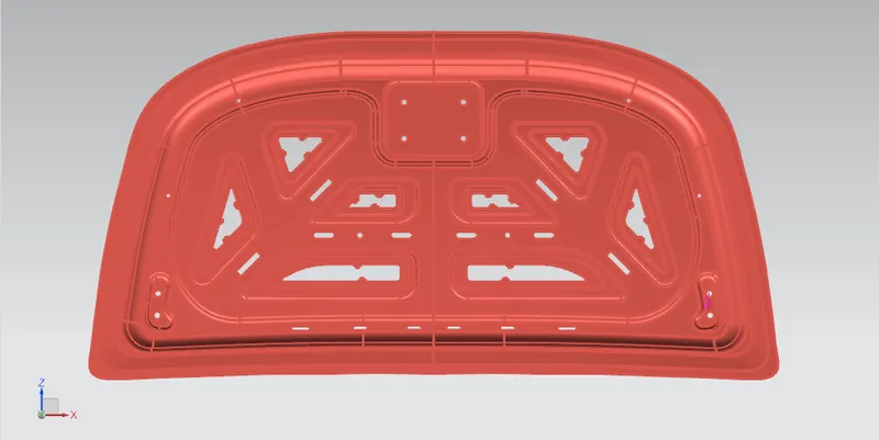
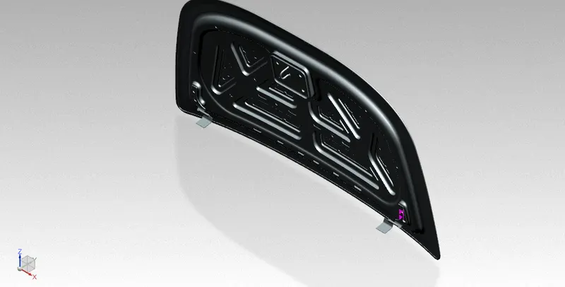
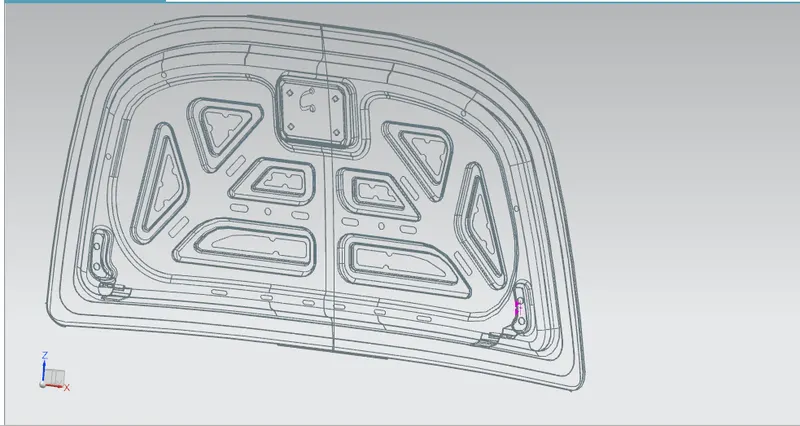
IMAGE 4) INNER PANEL WITH EMBOSS
Emboss
Emboss is an operation that adds stiffness to the part and are produced through deep drown process. The emboss are designed in such a way that it can dissipate impact forces outword swiftly and also reduces the head impact of the pedestrians.
The requiremnt and strength of emboss are validated by the CEA Team and suitable cutout are provided to faciliate proper attachemnt to the outer panel.
For feasible deep drown process the stamping direction are validates and a suitable draft angle is provided between the tool line and the part.
OUTER PANEL
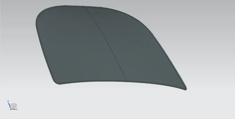
The outer panel is a styling surface where the edge of the panel are wrapped around the inner panel using hemming process.
HEMMING
It is sheet metal process where the edge of the part are wrapped around the surface using a roller.
Hemming is basically as an attachment procedure betwen to surface by reducing the impact of the spot welding on the aesthetic surface.
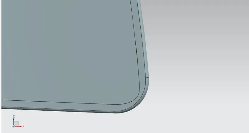
A cornor relief is provided along the rear and front edges during the hemming to improve quality of the outer panel styling surface and reduce intolerances and complexities.
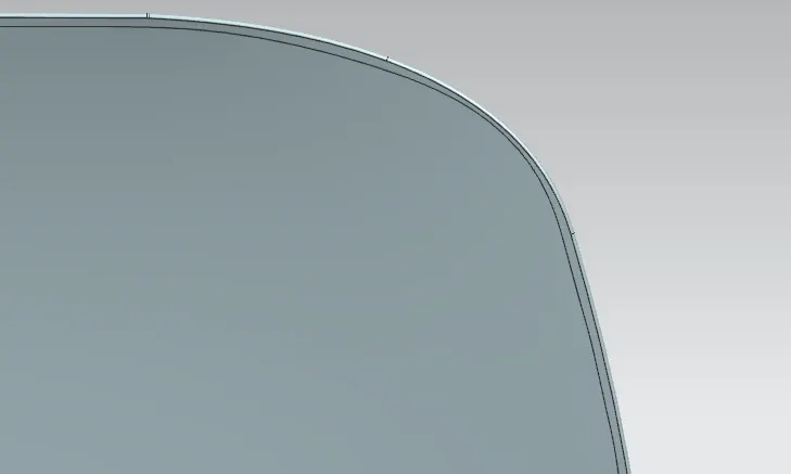
Rear Section and front Section relief
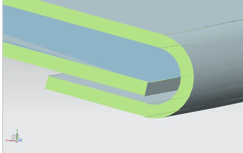
HOOD PANEL WITH HEMMING
REINFORCEMENTS
When adding attachement and weight to the hood the strength of that area is impacted locally and to compensate that reinforcement atructure are added.
HINGES
To actuate the movement of opening and closing of hood hinges are provided along with reinfrocement.
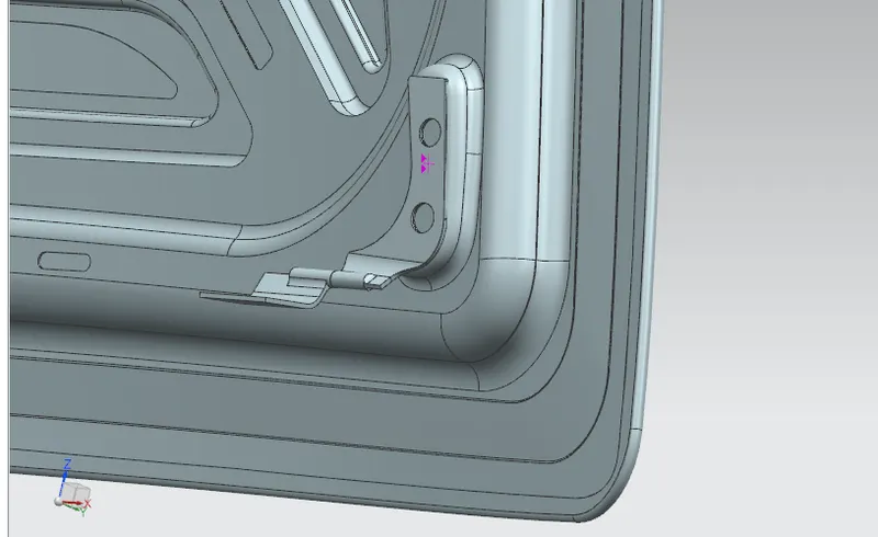
LATCH AND STRIKER POINT
The latch and stirker points faciliate the fixation of hood when closed and reinforcement are mounted impart strength on the Latch area.
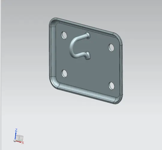
LATCH TRAJECTORY AXIS
For proper opening and closing of hood a trajectory axis is drawn to simulate the axis of movement of latch and striker situation. the desgn consideration for preparing trajectory axis are
- The latch and striker is provided to accommodate the hook and latch.
- The hinge are placed collinearly and a hinge axis are drived.
- From the hinge axis and local striker point a trajectory circle is drawn and the sriker point should be pependicular to that axis.
- Upon achieving pependicular between the trajectory axis and striker point a local emboss is provided for the hinge position.
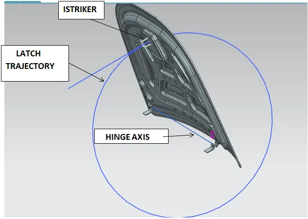
LATCH TRAJECTORY AXIS
This ensure the closing point of the latch and striker and also forms the predecessor to provides latch closing point on the engine compartment.
it also provide withering of the hood and seal the hood mounting perfectly during the closing situation. Thus it is one of the vital design considering in Hood Design.
MASTIC POIN
Mastic point are the area where the mastic adhesive sealant is applied that bonds the Outer panel and inner panel. Mastic sealant provides cover for 80mm locally and provides proper Hem flange bonding and considerably improve the NVH factor.
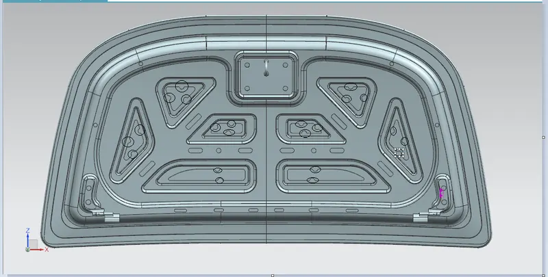
ASSEMBLY
Finally the part are assembled providing varius assembly constraints for the work part and restricting the degree of freedom.
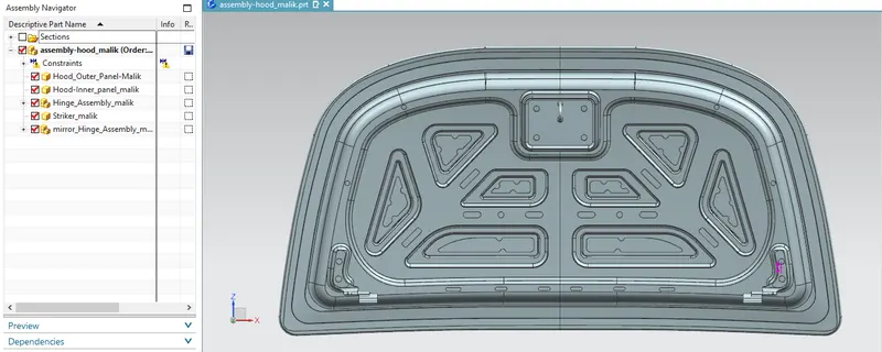
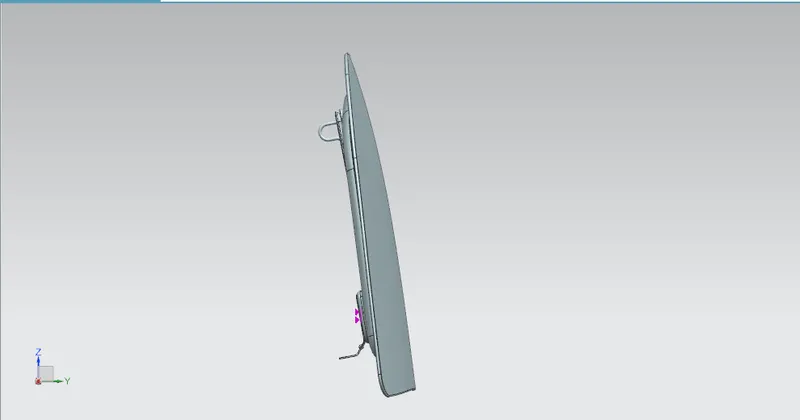
Front view of Hood
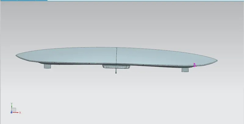
Hood upon closer Condition
CONCLUSION
Pessenger Vehicle Hood is designed in NX CAD by foloowing the master section data within the underlining design parameter by validating the Latch Trajectory and also adhering to the NCAp regulation standard.