Advanced Sheet Metal Design Using NX Cad Challenge_1_Casing Design
TITLE :
CASING DESIGN USING SIEMENS NX
OBJECTIVE:
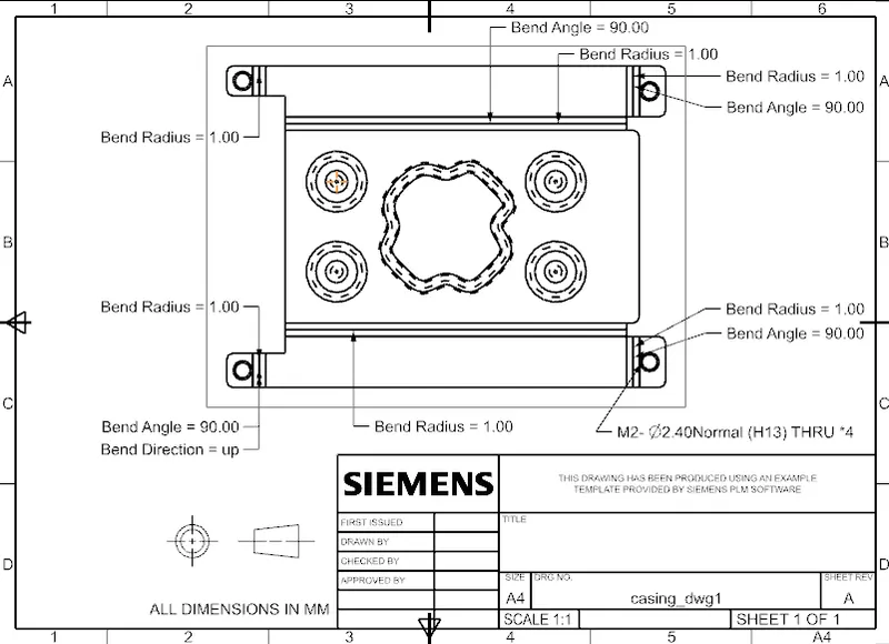
The sheet metal design of casing from the sketch dimensions and also incorporate the features needed and make the two dimensional represntation on a drawing sheet denoting the dimensions and orientation.
INTRODUCTION:
Sheet metal casing is a generic part which is used as the bodywork for most of component. Generally, they are preferred due to their easy malleability which makes the manufacturing process less complex and also a cost cutting procedure. Sheet metal is also strong and durable and also cost efficient than any other metal with properties on par.
These sheet metal are enhanced and designed to be in compact and hold the component parts and modules in tact. Therefore, even fixtures and locators are also designed and carried out making this desing aspect an inherent part of the product cycle.
In this project such a casing is designed using Siemens Product Life Management software (PLM) named NX. The design specifics are already provided and the dimensions are given beforehand. The design procedure and the methodology adopted are described further below.
DESIGN METHODOLOGY:
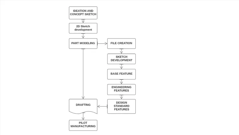
DESCRIPTION:
TOOLS
Sketch: This tool is used to create the elementary step in the process. It helps in creating the two dimensional sketch that can be developed into part. The orientation and the position are specified in the sketch support using the planes and origin.
BASE OR ENGINEERING FEATURES
Tab: One of the base feature, allows to extrude a sketch along a vector where the thickness or the length are taken global values predominantly or can be altered. Simply, it adds material to the planar sketch by a value.
Flange: This feature helps by bending a section with or without relief, at a specified angle and distance. These are again taken globally and can be altered to meet the specs needed.
Cutout: A specific area to be removed can be out drawn using the sketch feature and this cutout removes the projected sketch from the base part.
Hole: Creates a hole on a specified point, also the hole can be modified to adapt the fasteners with its standards as given input and clearance provided itself.
DESIGN FEATURES
Dimple: They are given to the surface to give support and improve the rigidity of the component, inturn better energy absorption. Also, they are oriented and aligned to produce aesthetic property.
Bead: They are again added to increase the stiffness of the component. NX allows to input the depth, radius of the bead along with it the die and punch radius are also described in this feature.
Break Corner: Adds a preset fillet value to the edges extruding sharper.
SHAPING FEATURES
Bend: Modifies the part by bending a section along a sketch line at perpendicular orientation with reversable directions.
Unbend: Does the pretty much opposite of the above, used to maintain the datum of the part and avoiding complexity in creating CSYS separately.
Rebend: As the name itself suggests, rebends the unbended component. Differs from bend by bending the component with its earlier orientation in memory.
Mirror: Produces the specific feature mirror image along a center line or plane to reduce the repitition of creating separate sketches and features.
DRAFTING FEATURES
Flat pattern: Creates the flat metal appearance from the formed sheet metal part which can be used to draft, making the understanding better and less complex.
CASING:
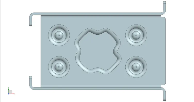
TOP VIEW
FRONT VIEW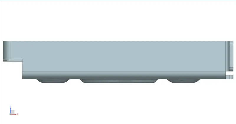
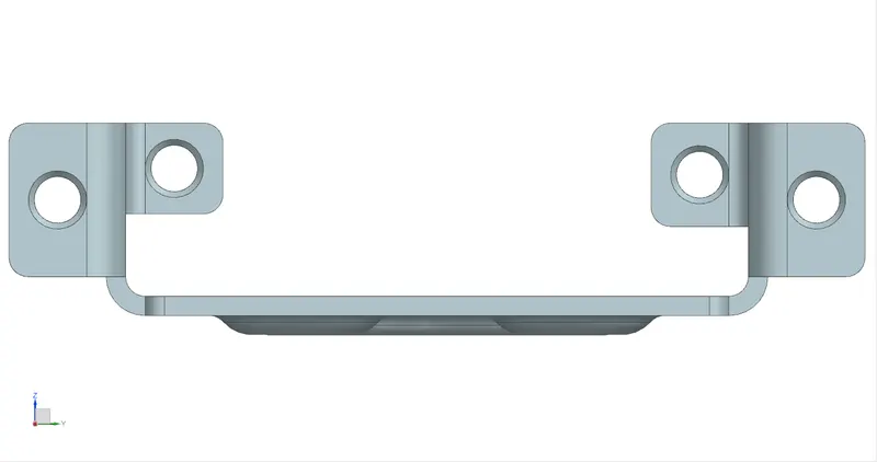
SIDE VIEW
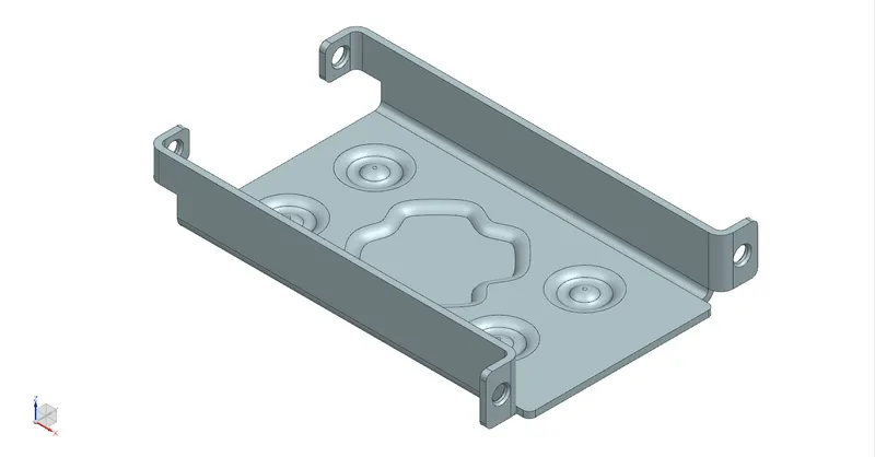
ISOMETRIC
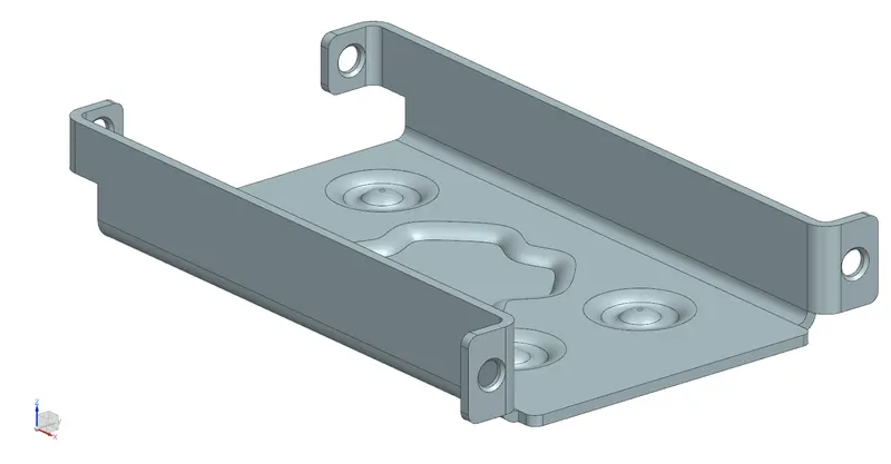
TRIMETRIC
DRAFTING:
CONCLUSION:
The casing design using Siemens PLM NX has been successfully developed using the given representation.