Adams Assignments – Problem 5 – Compliance
AIM :-
To perform the appropriate simulations of a rear multilink suspension assembly to obtain the following parameters.
- Brake steer (deg/m).
- Traction steer (deg/m).
- Longitudinal wheel center recession (mm/KN).
- Lateral force compliance steer (deg/KN).
- Lateral force compliance camber (deg/KN).
- Bump steer.
After obtaining the above parameters, tune a single parameter of the assembly to obtain the following targets.
- Bump steer of +2.6 deg/m.
- Traction wheel center recession stiffness of ~500 N/mm.
- Camber compliance of 0.45 deg/KN.
ASSEMBLY MODEL :-
The rear multilink assembly is created by importing the MDI_REAR_MULTI_LINK.sub file, and the assembly is loaded after clicking on apply.
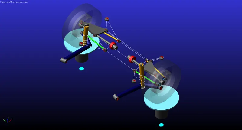
Once the assembly is loaded, the appropriate simulations are run to obtain the parameter values.
BRAKE STEER, TRACTION STEER AND WHEEL RECESSION :-
The simulation run to obtain the brake steer, traction steer and longitudinal wheel recession center is the same which is the static load simulation. Here the input forces are varied depending on the parameters to be plotted.
Brake steer,
For brake steer analysis, the braking force input is provided between 0 to 3500 N. The number of simulation steps is 250.
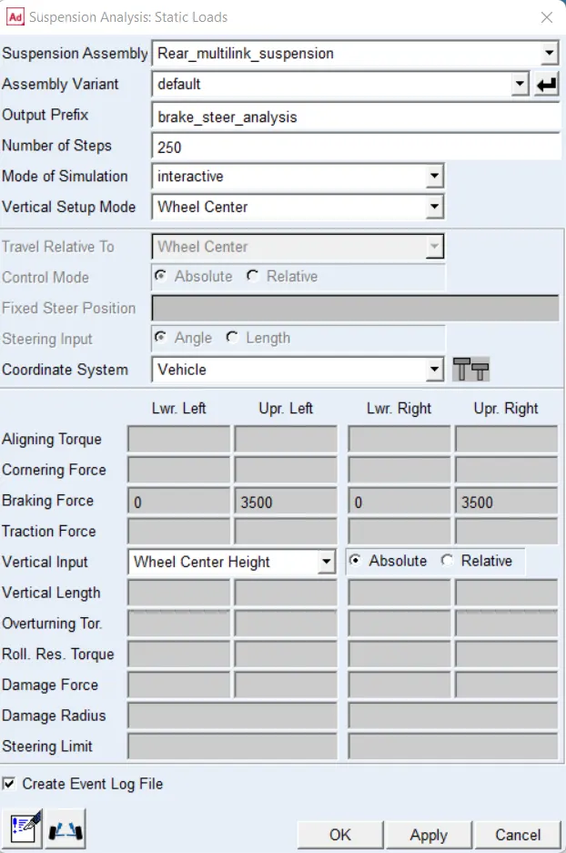
The simulation is run and the brake steer is plotted.
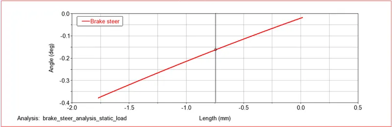
The brake steer is the slope of the toe angle vs the wheel base travel and it is 200 deg/m. The suspension is in toe out during braking as shown by the negative sign for the toe angle.
Traction Steer,
For traction steer analysis, the traction force input is provided between 0 to 3500 N. The number of simulation steps is 250.
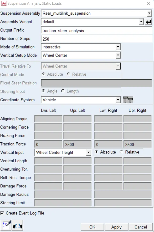
The simulation is run and the traction steer is plotted.
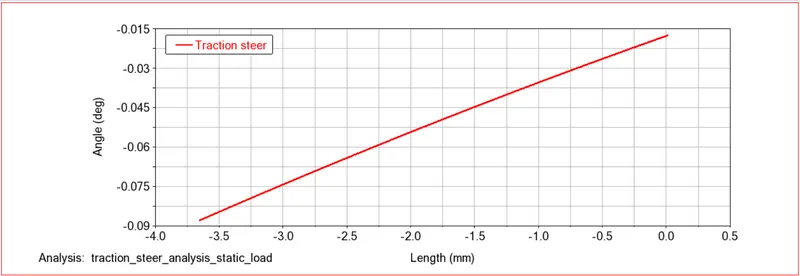
The traction steer is the slope of the toe angle vs the wheel base travel and it is 19.2 deg/m. The suspension is in toe out under traction as shown by the negative sign for the toe angle.
Longitudinal Wheel Center Recession Under Traction and Braking,
The same simulation parameters used for brake and traction steer are taken into consideration to plot the wheel recession.
The longitudinal wheel center recession under traction is given below.
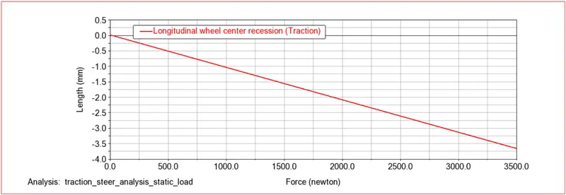
The wheel recession under traction is the slope of the wheel base travel vs the longitudinal wheel load. The recession is 1 mm/Kn.
The longitudinal wheel center recession under braking is given below.
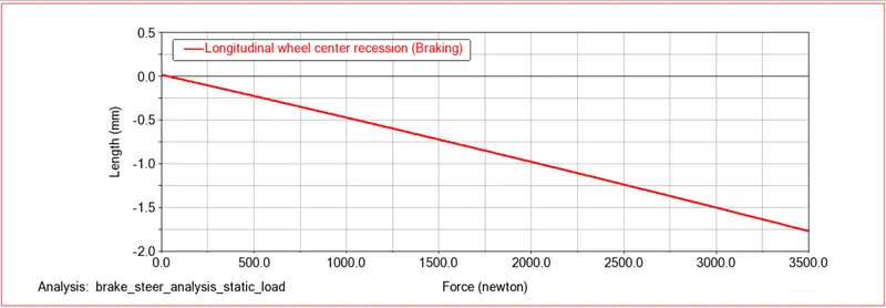
The wheel recession under braking is the slope of the wheel base travel vs the longitudinal wheel load. The recession is 0.51 mm/Kn.
LATERAL FORCE COMPLIANCE STEER AND CAMBER :-
The lateral force complinace steer and compliance camber are obtained by running the static load simuation where the input is the cornering force. The force is varied from 0 to 3500 N and the number of steps of the simulation is 250.
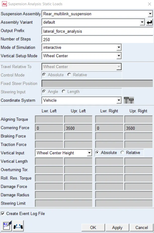
The simulation is run and the compliance camber and compliance steer are plotted.
Lateral Force Complinace Steer,
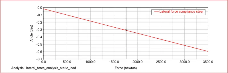
The compliance steer is the slope of toe angle vs the lateral wheel load and the value is 0.164 deg/KN. The suspension is in toe out while cornering which results in an oversteer effect.
Lateral Force Compliance Camber,
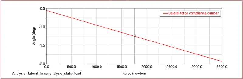
The compliance camber is the slope of the camber angle vs the lateral wheel load and the value is 0.394 deg/KN. The suspension has a negative camber during cornering which results in an understeer effect.
BUMP STEER :-
To obtain the bump steer, parallel wheel travel simulation is run where the number of steps is 250 and the suspension travel is 100 mm in jounce and rebound. The simulation is run and the bump steer is plotted.
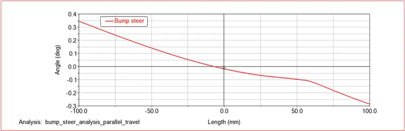
The bump steer is the slope of the toe angle vs the wheel travel and the value is -2.5 deg/m. This indicates that the suspension is in toe out and causes an oversteering effect.
TUNING THE ASSEMBLY TO OPTIMIZE BUMP STEER :-
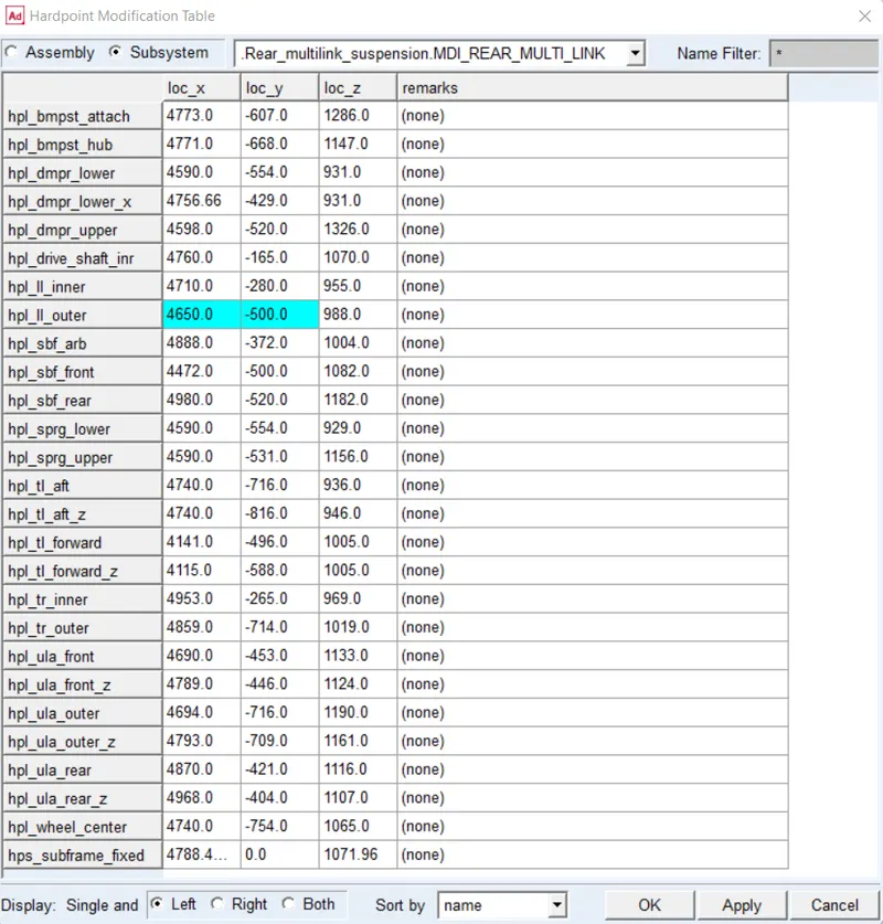
To optimize the bump steer to get +2.6 deg/m, The hardpoint of the outer lower link is modified which is shown below.
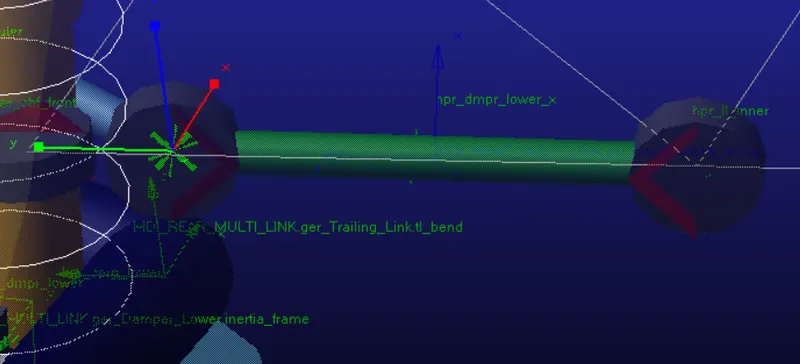
The X and Y coordinates of the hardpoint are varied and through trial and error, the coordinates shown in the table below are that required to achieve the target bump steer.
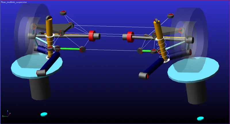
This has a drastic effect on the geometry of the lower link as shown in the image below.
Once the hardpoints are modified, the parrallel wheel travel simulation is run with the same inputs and the bump steer is plotted.
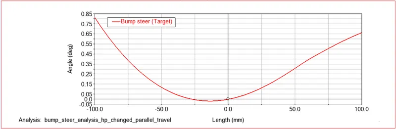
The bump steer is 2.5 deg/m and the suspension is in toe in which now produces an understeer effect.
TUNING THE ASSEMBLY TO OPTIMIZE WHEEL RECESSION STIFFNESS :-
The bushing selected to be tuned is the trailing arm bushing. This bushing is selected because the trailing arm has the largest moment to the wheel center.
The property file of the bushing is opened and the stiffness of the Fx component is calculated and is 4500 N/mm. The stiffness of the Fx component is modified to achieve the wheel recession stiffness target of 500 N/mm.
Through trial and error, the bushing stiffness is set to 210 N/mm, and the Fx component is modified as shown below.
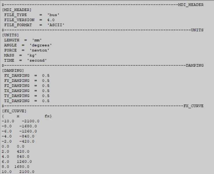
The new property file is loaded and the static load simulation is run where the inputs are 250 steps and traction force from 0 to 3500 N. The graph is then plotted as shown below.
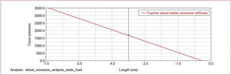
Here the stiffness is the slope of the longitudinal wheel load vs the wheel base travel and the value is 501.91 N/mm which is close to the target.
TUNING THE ASSEMBLY TO OPTIMIZE CAMBER COMPLIANCE :-
To achieve the target camber compliance the bushing of the upper control arm is selected. It is chosen because the bushing being connected to the knuckle affects the camber changes.
The property file of the bushing is opened and the stiffness of the Fx component is calculated and is 4500 N/mm. The stiffness of the Fx component is modified to achieve the camber compliance target of 0.45 deg/KN.
Through trial and error, the bushing stiffness is set to 2300 N/mm, and the Fx component is modified as shown below.
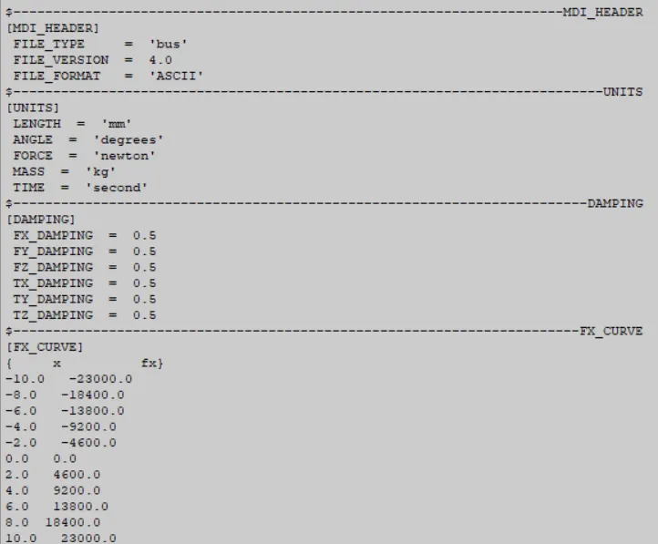
The new property file is loaded and the static load simulation is run where the inputs are 250 steps and cornering force from 0 to 3500 N. The graph is then plotted as shown below.
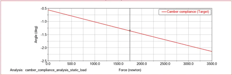
The camber compliance is 0.45 deg/KN, which is the target to be achieved.
CONCLUSION :-
The appropriate simulations are run to obtain the parameters and the required components are tuned individually to achieve the respective targets.