3D Creation of Celing, Roof, Architectural plan, Structural plan, Sectional view, Elevation view and Camera specific view for a house plan using REVIT
Solution.1)
Aim: To provide a ceiling using options from the architecture tab above the walls at the first-floor level.
Procedure:
- Open the project from the local computer in Revit.
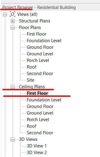
- In the project browser panel, open the First Floor level of your project under Ceiliing plan.
- Go to the ceiling option in Architecture tab.
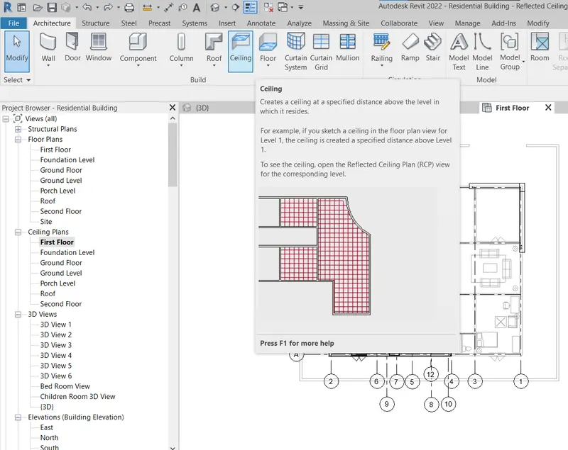
- After clicking on the Ceiling option one have two options either to select Atomatiic create ceiling in closed boundary walls or sketch manually different designs of ceiling as per his requirements.

- Let us use an Automatic ceiling for the rest of the house except for the Living room where we will use Sketch Ceiling Option to model a ceiling.
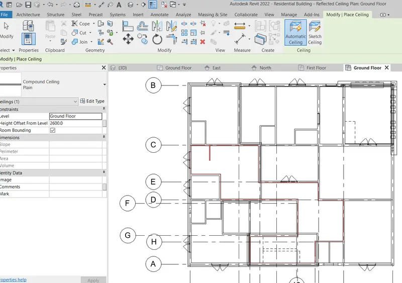
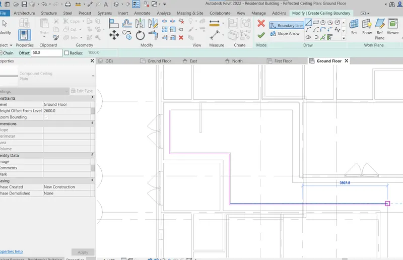
- After that select the area of the house where one wants to create a ceiling. We can see a red boundary over that area when we hover our mouse above that as shown in below figure.
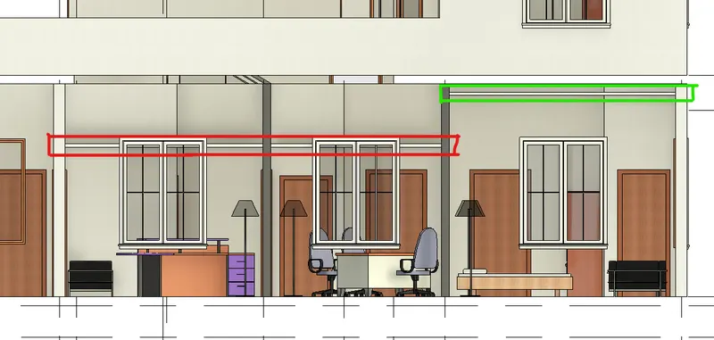
- If we observe from the front view we can see the ceiling height is a little bit below the top of the window level. We can adjust that using the properties tab by specifying the Top offset level(in our case we will provide a level of 3500 mm. from the base level of the respective floor.
- Now will make the ceilings for part of the Stairs, Living Room and Dining room by sketch.
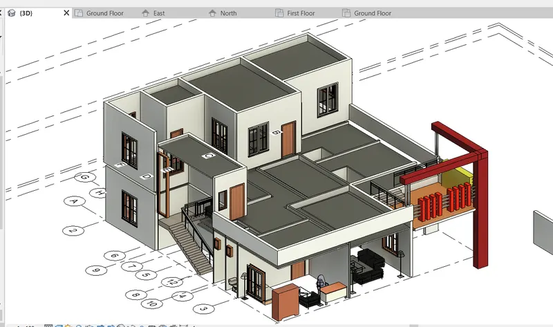
- After making ceilings for all rooms, Living, Stairs and Dining rooms on the ground floor and first floor, our 3D model will look like as shown in fig. (Note: Floors, Roof and Some walls are hidden to get the good visuals of ceilings.
- After making we can unhide the walls, floor and roof. A view showing roofs, floor and ceilings are shown in below figure.
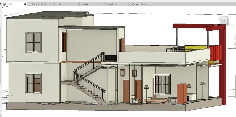
Result: We have modelled the Ceilings for the Ground Floor and First Floor for all the part of the Building.
Solution.2)
Aim: Model a roof above the ceiling by selecting the footprints of the ceiling. Also to adjust the slope of the roof to 10 degrees using the on-screen adjust roof slope option.
Procedure:
- Since we have a 2 Storey Building we need to make a roof on the top of the first-floor level (Level Wise at Second Floor).
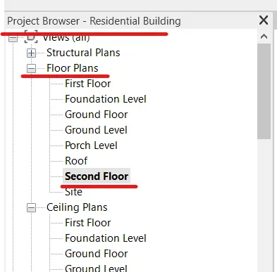
- Open the Second floor under Floor plans from the project browser option.
- Under the Architecture tab, click on the roof option, under that also select Roof by footprints.
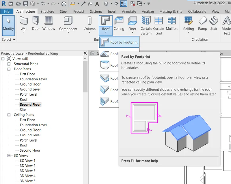
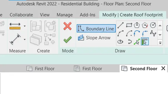
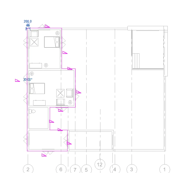
- Using the tools, make a layout of the roof plan above the wall boundary and click on the Green Tick.
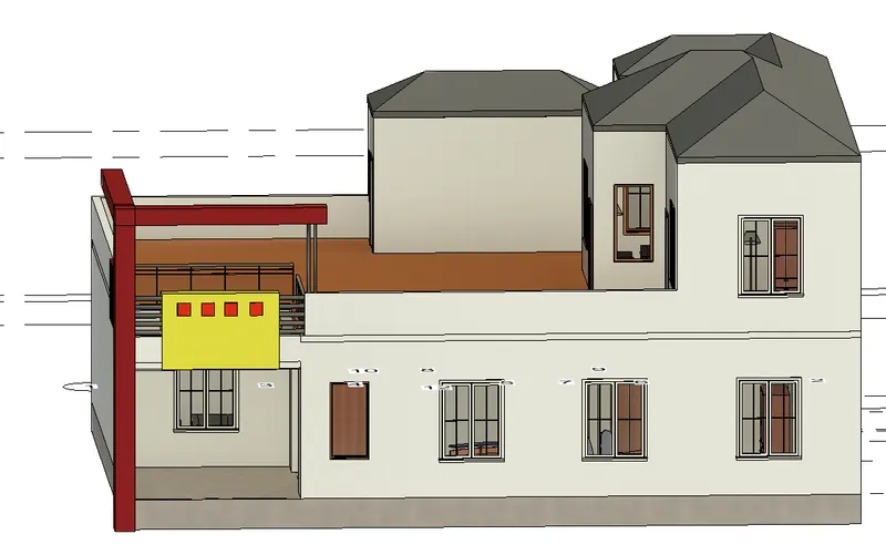
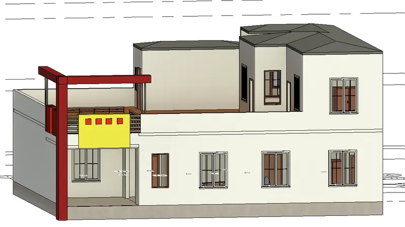
- Our building will look like this.
- We can adjust the slope of the roof from the properties option as shown in the figure.
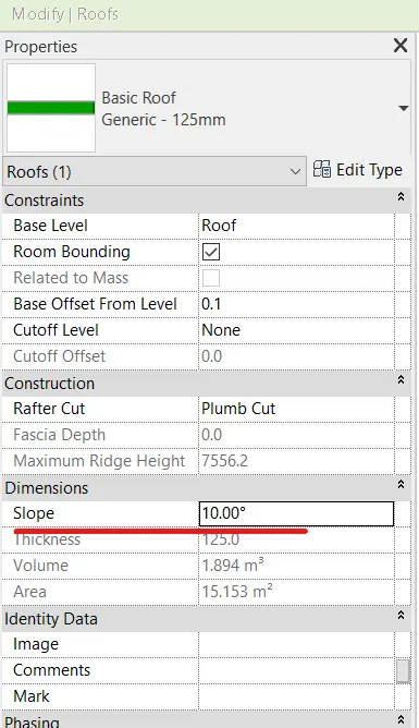
Result: We have provided a roof for our building will slope of 10 degrees and our building look like this at this stage.
Solution.3)
Aim: To create plan views for ground floor level, first floor level including all the walls, floors and components and separate them to architecture and Structural Plans.
Procedure:
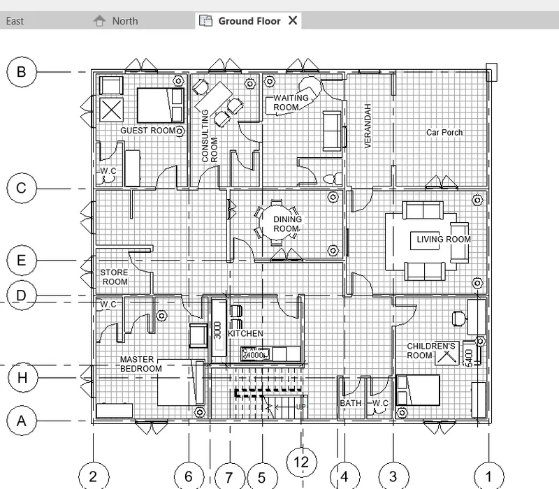
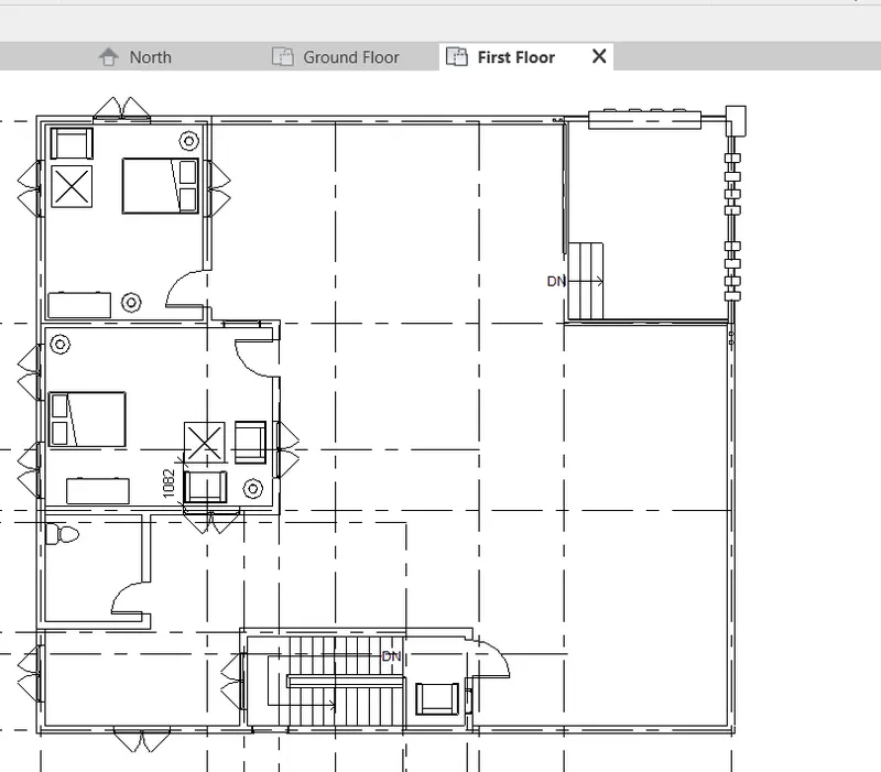
- From the project browser on the left side, we can get the option to view the floor plans for our project, but since we have used an Architectural Template, these floor plans are Architectural Floor plans.
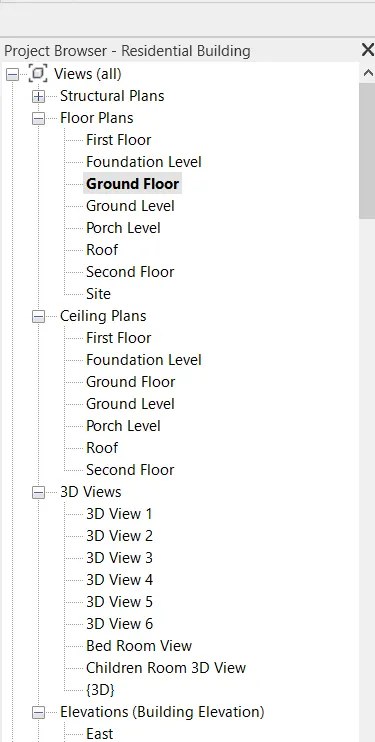
- Below is the Architectural floor plans of the Ground Floor and First Floor.
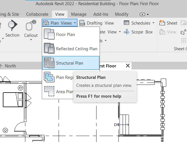
- To obtain a Structural Plan, we have to go to View Tab and select Structural Plan View under the Plan View option as shown in fig. and then select the level for which we need to obtain the Structural Plan.
- Below are the Structural plans obtained for the Ground Floor and First Floor.
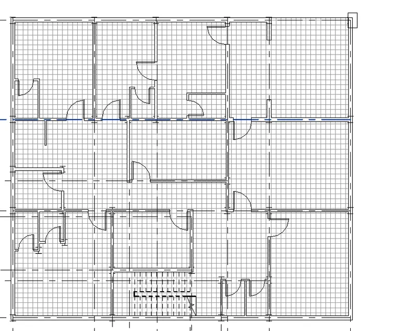
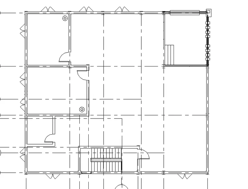
Fig. Ground Floor Fig. First Floor
Result: Architectural and Structural floor plans for Ground Floor and First Floor has been obtained.
Solution.4)
Aim: Using Annotate toolbar to add dimensions to all the walls and floor with reference to the longitudinal and transverse grids created in the project file.
Procedure:
- For Architectural Plan, we need to specify the dimensions of the Wall, Boundary, Thickness and Positioning of the wall.
- Go to Annotate Tab and select the dimensioning option as per the need for dimensioning and annotate all the possible measurements.
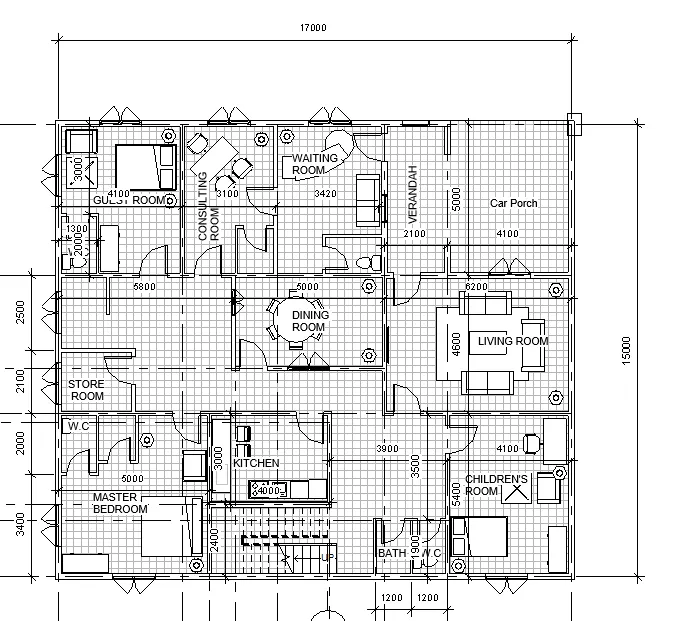
Fig. Architectural Ground Floor Plan with Dimensions.
- For Structural Floor Plans, again using the Annotate Tab and Dimensioning tool. All the measurements are taken given proper dimensioning.
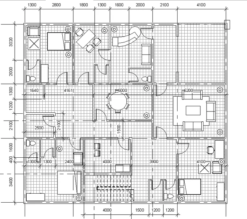
Fig. Structural Ground Floor Plan
Result: We have used given proper dimensions to our plan for both Architectural and Structural Ground Floor Plan.
Solution.5)
Aim: To create a sheet template from the view tab and adjust the parameters on the sheet to add appropriate views.
Procedure:
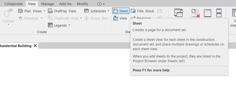
- Go to view tab, and select Sheet option to create a sheet as shown in fig.
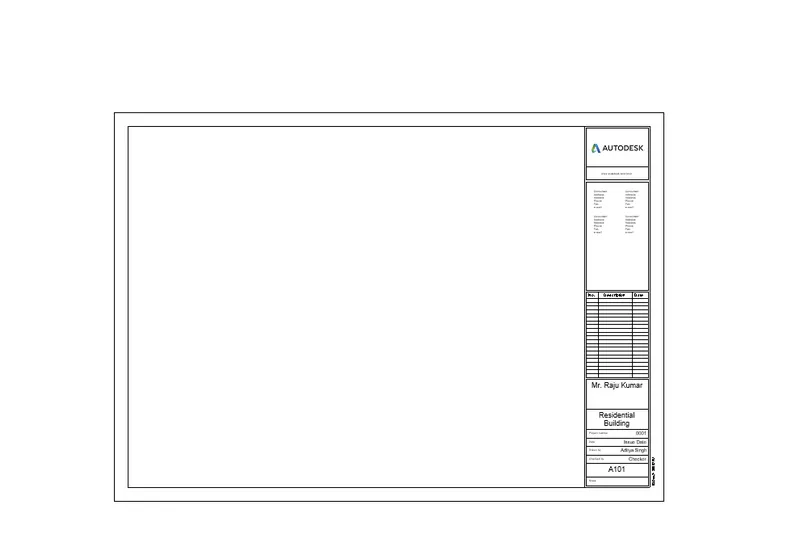
- A new sheet will appear on the as shown in fig.
- One can edit the information displayed on the Sheet either from the Properties panel or either direct from the sheet. Both options have been shown in below fig.
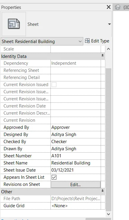
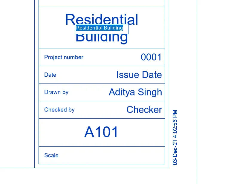
Fig. Changing information via Properties Panel Fig. Changing information directly from the sheet.
- One can also use Project Information option under Manage tab and add information in the popped up dialogue box as shown in fig.
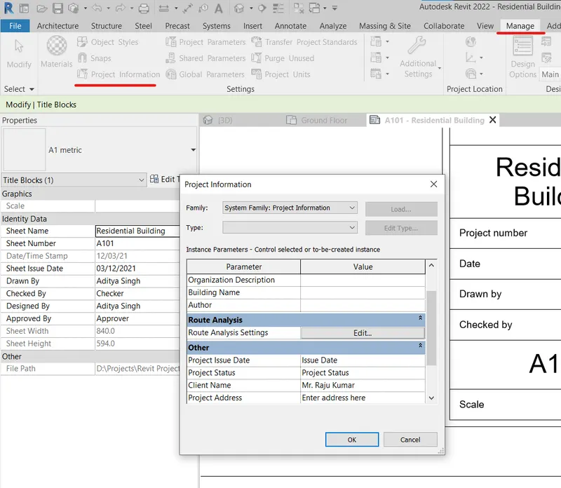
Result: Sheets has been added and Projecct Information has been added.
Solution. 6)
Aim: To create elevation view using the elevation tab create the elevation views, looking at your building from East, North, South, and West.
Procedure:
- Go to the View Tab, under that select Elevation. Select the direction from which one wants get the elevation view. We have marked the four direction i.e., East, West, North and South Direction.
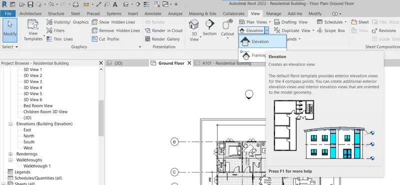
- Now go to the project browser panel, and Under Elevation option click to open Elevation views from all four directions as shown in fig.
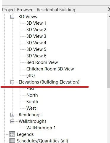
- All the four elevation views are shown below.
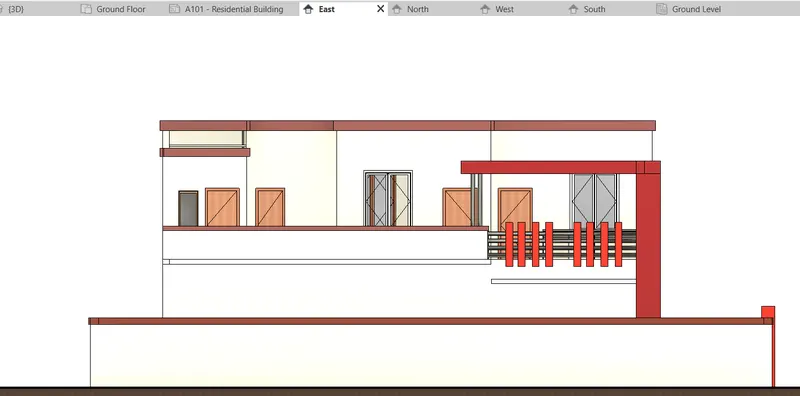
Fig. East View
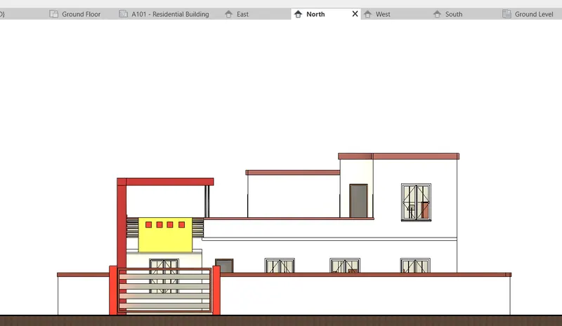
Fig. North View
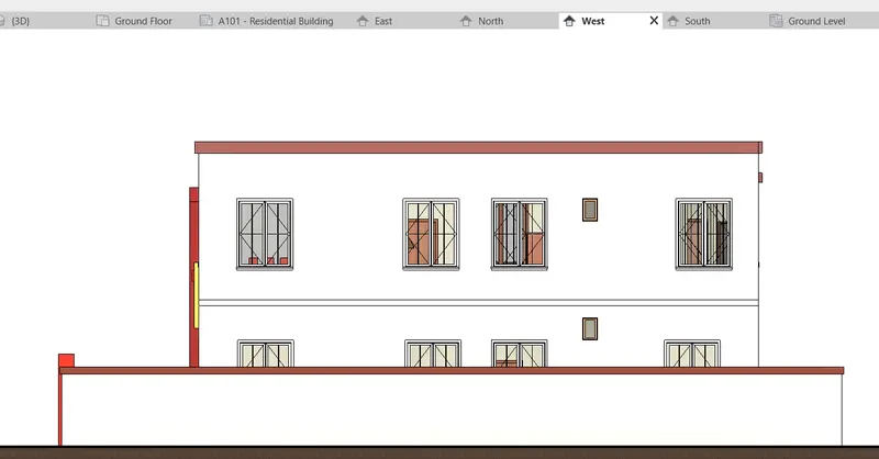
Fig. West View
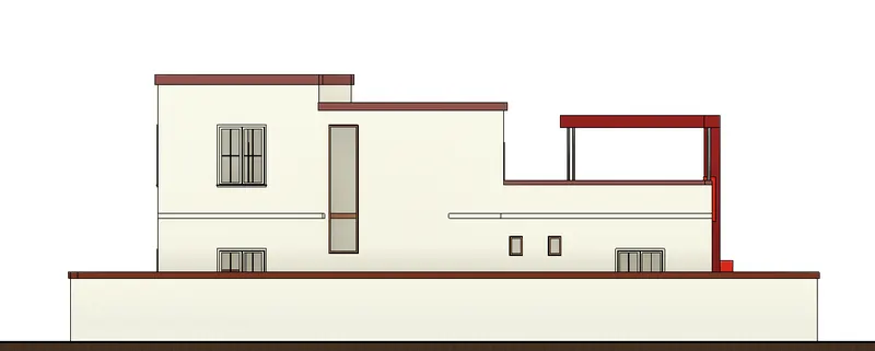
Fig. South View
Result: We have created Elevationn views for East, West, North and South Directiion.
Solution: 7)
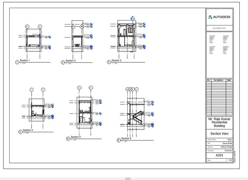
Aim: To Produce section cut through each room either cutting across longitudinally or in a transverse direction
Procedure:
- Go to View Tab and Select Section option to create Section as shown in fig.
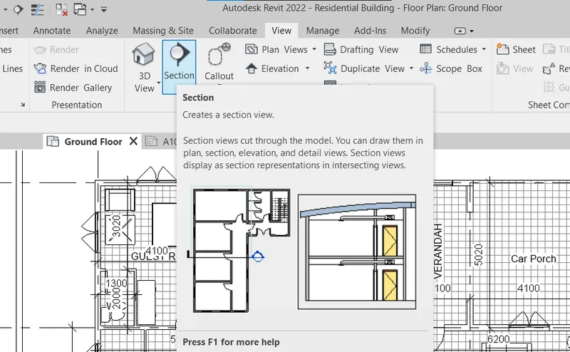
- We have created Secion View for all rooms and Stairs.
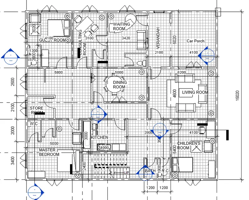
- Under Project Browser, sections view can be opened. All the Section Views created are shown below.
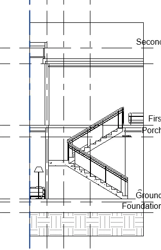
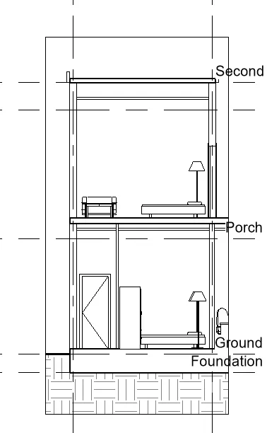
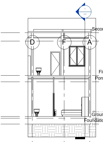
Result: Section Views for Rooms and Stairs has been made.
Solution.8)
Aim: To classify the views, Plan Views, Section Views, and Elevation views to either Design or Documentation category using Properties browser
Procedure:
- From the property browser, right-click on the View all label, and select browser organisation.
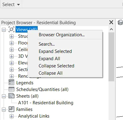
- A dialogue box will appear, click on New and Name it as Design or Documentation.
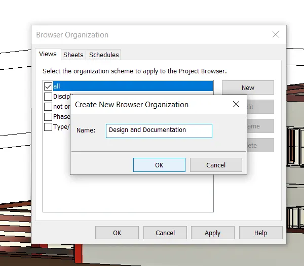
- Click Apply and Ok.
- Now the project Browser has been organised in a new manner.
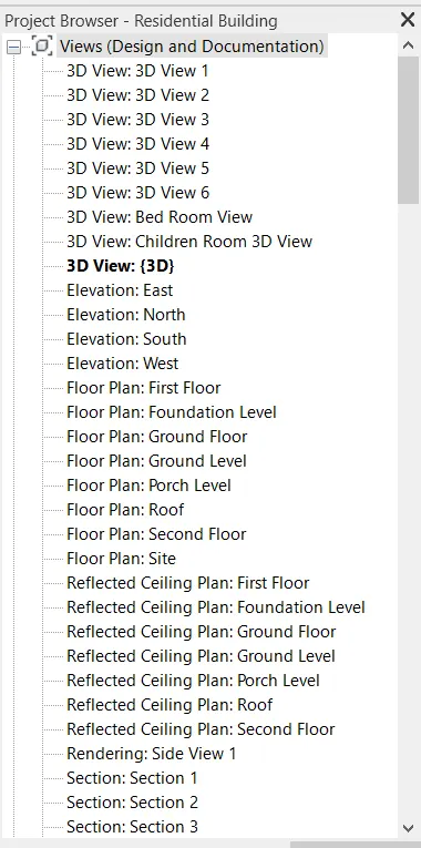
Result: All the Plan Views, Section Views and Elevation Views are classified under Design and Documentation Category.
Solution.9)
Aim: Using the sheet template produced create multiple sheets as follows
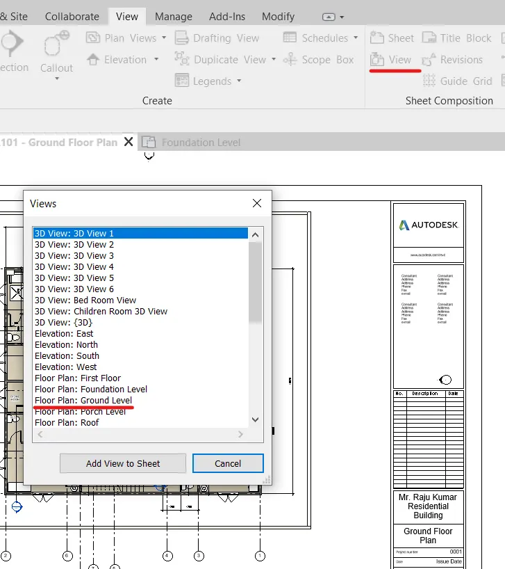
a. A 101- Ground Floor Architecture Plan
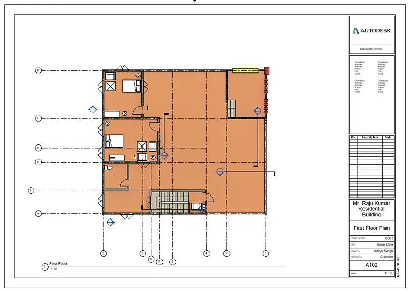
b. A 102- First Floor Architecture Plan
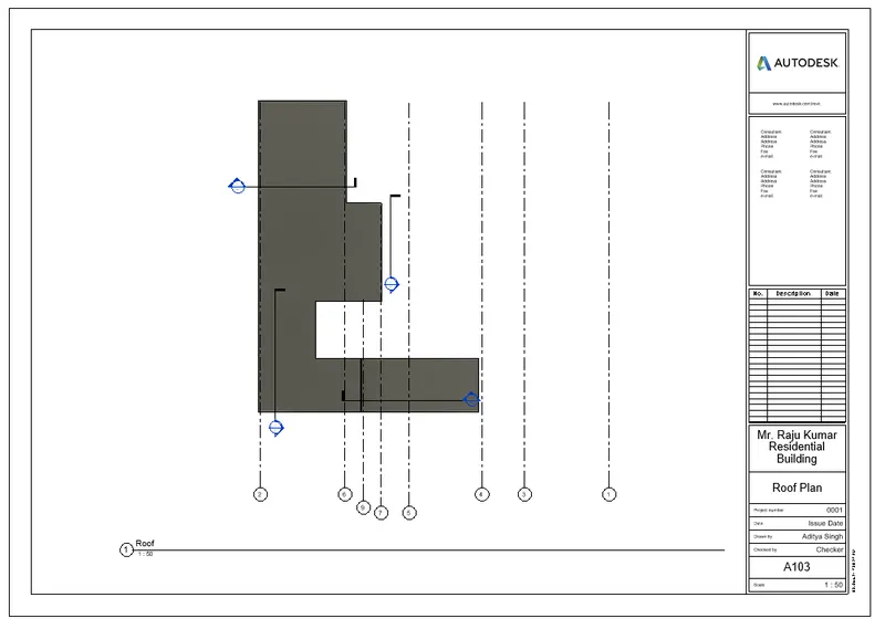
c. A 103- Roof Plan
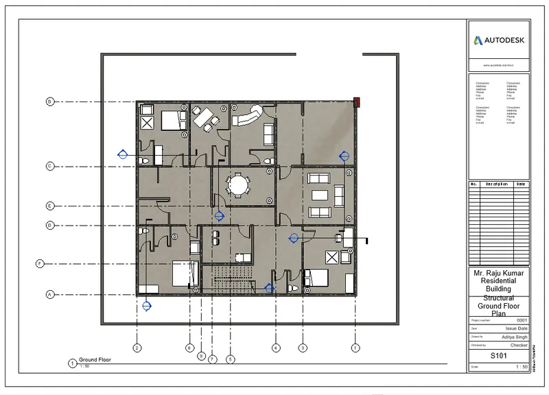
d. S 101- Ground Floor Structural Plan
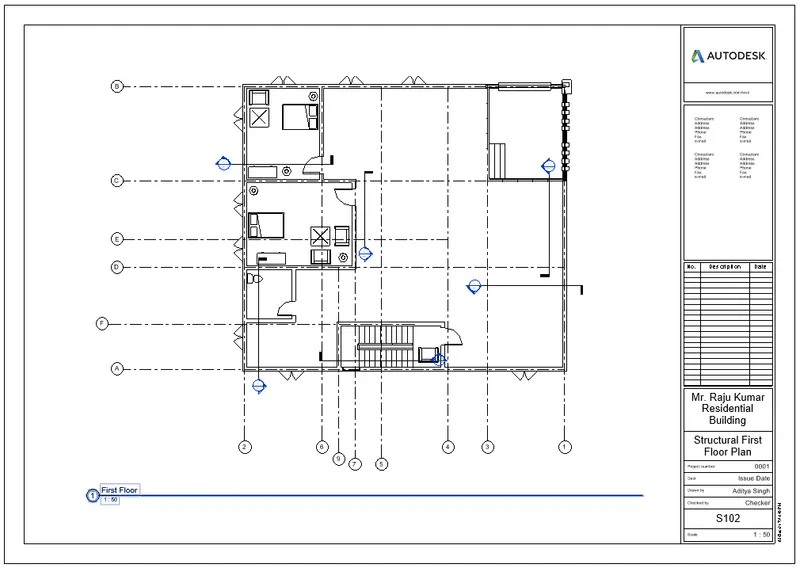
e. S 102- First Floor Structural Plan
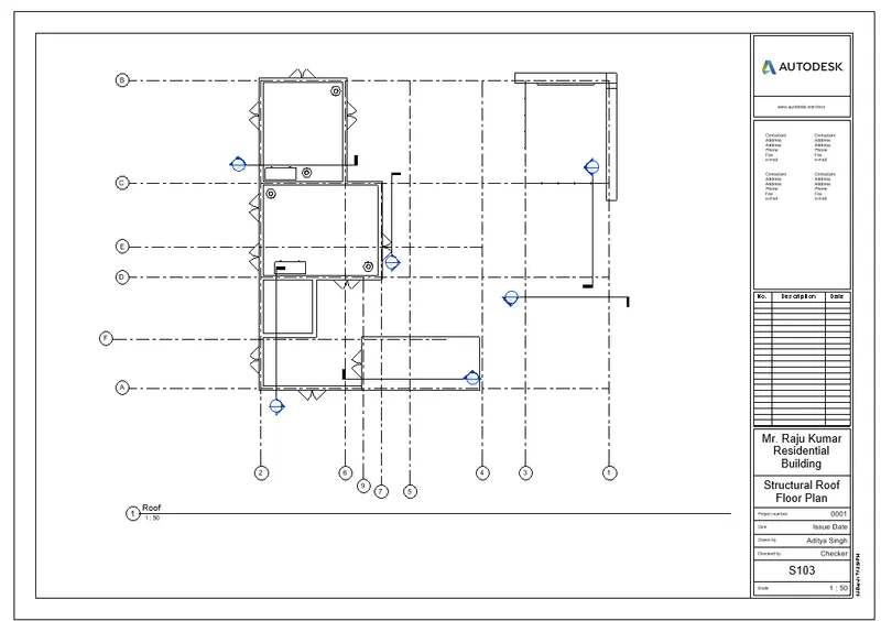
f. S 103- Roof Framing Plan
g. A-201- North-South Elevations
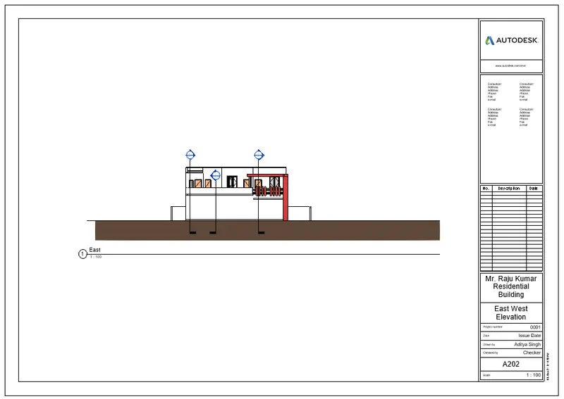
h. A-202- East-West Elevations
Procedure:
- Go to View Tab, Select View Option under Sheet Option, a dialogue box will appear, click on the view that we want to place on the Sheet.
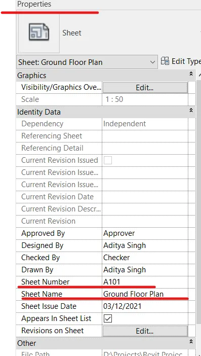
- We can use the Property Browser to Change the Sheet name, sheet Number as per the requirement.
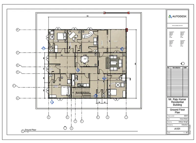
- Below are the Sheets with Names and Numbers with specified Views as asked in the question.
- A 101- Ground Floor Architecture Plan
- A 102- First Floor Architecture Plan
- A 103- Roof Plan
- S 101- Ground Floor Structural Plan
- S 102- First Floor Structural Plan
- S 103- Roof Framing Plan
- A-201 North-South Elevation View

- A-202 East-West Elevation View
- Section View
Result: All the corresponding Views have been obtained on the Sheets with Sheet Names and Sheet Numbers.
Solution.10)
Aim: To create a camera-specific view or a 3D view in each room ( living, dining, bedroom).
Procedure:
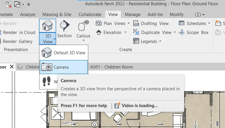
- Go to view, then 3D View option under that select camera and then place the camera at appropriate angle in each room to create a view.
- Below are the sheets with Camera View of each room.
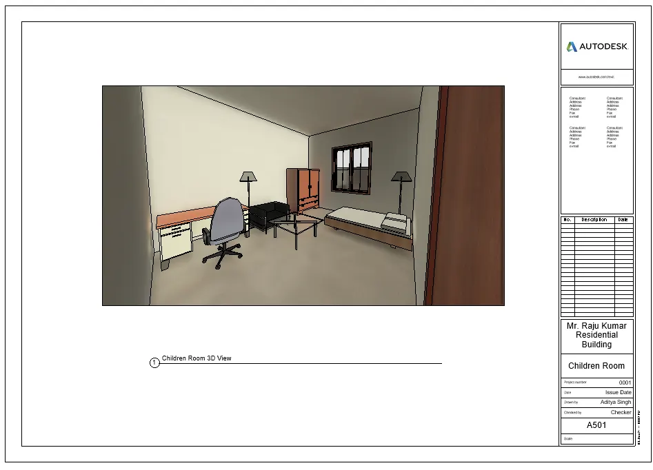
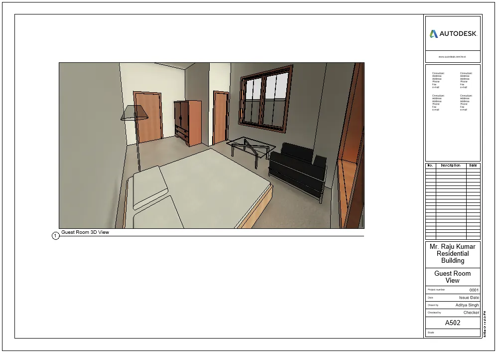
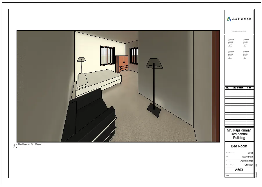
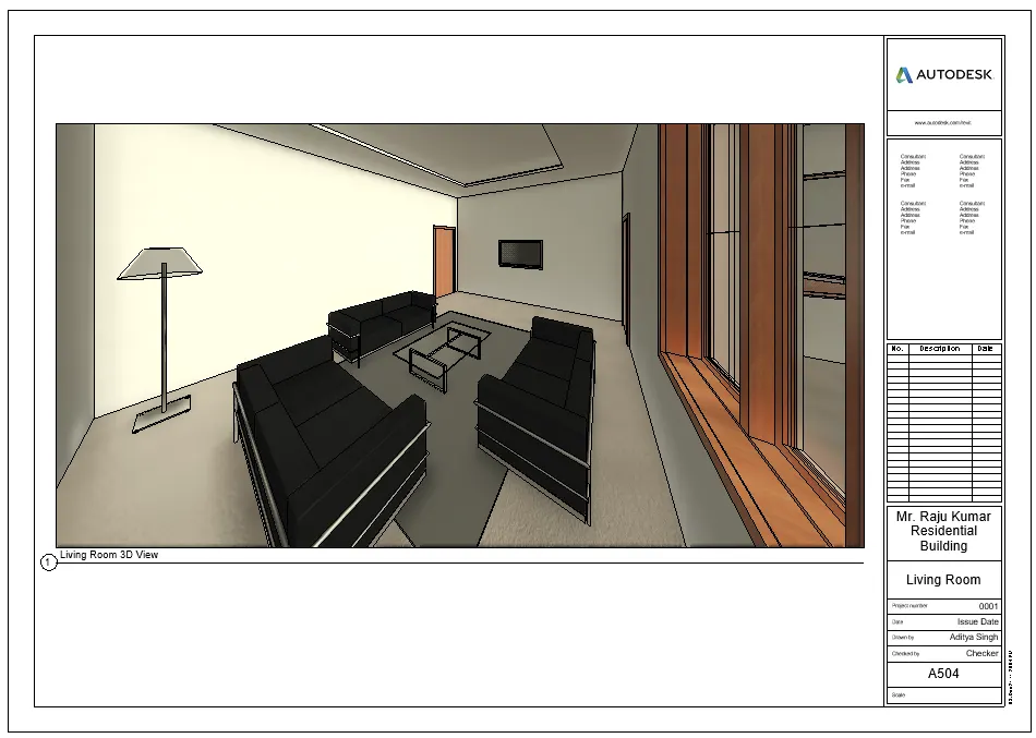
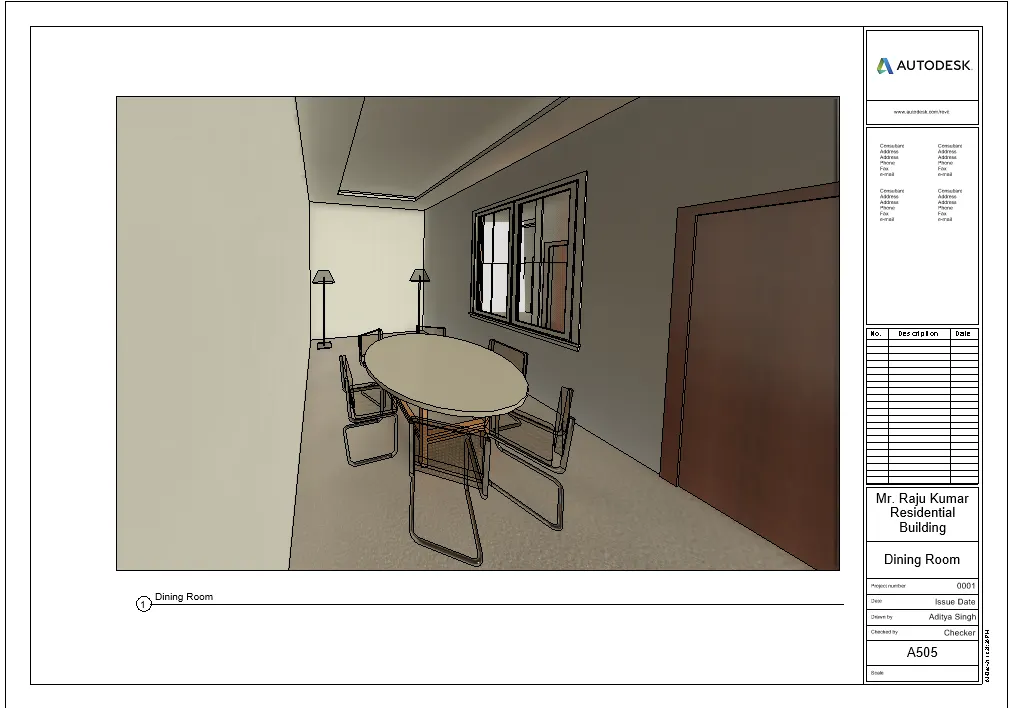
Result: All the views are obtained on the sheets with Sheet Number 501.